We propose a ring resonator-based orbital angular momentum carrying vortex beam generator design with high vertical directional emission efficiency. By adopting a vertically asymmetric grating structure in the ring resonator, optimized for enhanced vertical emission, an emission efficiency in one direction reaches as high as 78%, exceeding the 50% theoretical limit of previously designed vertically symmetric grating-assisted ring resonator-based structures.
An optical vortex beam carrying orbital angular momentum (OAM) has attracted a lot of interest due to its potential applications in communication [1] and quantum computation [2]. Recently, a compact integrated OAM generator using a ring resonator with angular side grating was demonstrated [3], in which extracting light from whispering gallery modes of the ring resonator to free space carried well controlled OAMs. The device is only several microns across [3], enabling large scale integration for on chip OAM generation. However, the device suffers from a relatively low vortex beam emission efficiency. A theoretical work based on the same device reported a maximum efficiency of 28% [4], while an experimentally demonstrated devices showed emission efficiencies from 3 to 13% [3]. This is partly attributed to the vertical symmetry of the device. The emission efficiencies to the top and the bottom free spaces should be identical owing to the vertical symmetry, so that the maximum emission efficiency in one direction cannot exceed 50% even if perfect conversion from an input light into vortex beams is achieved.
Vertical asymmetric OAM generator designs have been previously proposed for different design purposes, such as resonant mode selection and suppression [5], tuning opportunities [4], or ease of fabrication [6]. However, a design exploiting vertical asymmetry to achieve strongly directional radiation with enhanced vertical emission efficiency was not previously proposed, and recently proposed vertical grating structures demonstrated no significant directional preference of emitted OAM [3]. It is important to achieve as high a waveguide-to-free space radiation efficiency as possible in many OAM light applications such as quantum computing [7] or quantum communication [8]. In this work, we propose an implementation of modified vertically asymmetric grating structure to generate OAM with high directional emission efficiency. By breaking the vertical symmetry of the device, that is, placing the grating on top of the device and optimizing the grating for vertical directional emission efficiency, we obtained a theoretical waveguide-to-OAM emission efficiency as high as 78% in one direction, exceeding the theoretical limit of previously designed vertically symmetrical structures.
II. ASYMMETRIC DECAY RATE WITH ASYMMETRIC GRATING
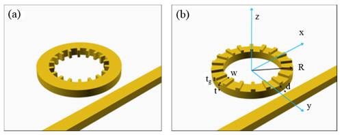
Figure 1 illustrates both the previously suggested (side-grating assisted ring resonator) integrated OAM generator and our proposed modified directional OAM generator based on the ring resonator with top-grating. In both structures, the light coupled to each ring resonator is scattered by the grating while it travels along the waveguide in the ring resonator. The side-grating in Fig. 1(a) scatters the traveling light into the upper and the lower free-spaces equally owing to the vertical symmetry of the waveguide geometry in the ring resonator. Whereas, in the top-grating structure, the vertically asymmetric waveguide geometry makes it possible to enhance the scattering into the preferred direction selectively.
Previously, a general asymmetric decay (or coupling) behavior of a resonator couple to two ports has been studied [9], which reveals that the decay rate ratio (τ1/τ2) into the two ports is related to the background reflection of the ports as follows:
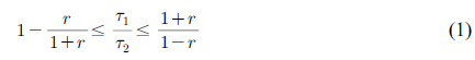
where the decay rate into each port is given by 1/τi, I = 1, 2, and r is a background reflection coefficient of each port, not the one for the whole system. For example, let us consider a slab waveguide with a 2D grating on its upper side, which can be treated as a resonator coupled to two ports with external decay (coupling) rates to the upward and downward regions of a free-space (τup and τdown). When the light is incident into the slab grating from the free-space, a guided-mode resonance occurs [10]. At the same time, the partial reflection on the surface brings about a Fabry-Perot resonance, which then generates the background reflection. According to Eq. (1), in the case of r = 0, which is frequently assumed for simplicity in many theoretical analyses of the slab grating related structures, the ratio of the external coupling rates (τup/τdown) should be 1, implying a symmetric coupling behavior. On the other hand, τup/τdown can be infinite in theory, implying perfect directivity, when r = 1. Such a case, however, is meaningless since r = 1 means the incident light is completely reflected by the Fabry-Perot resonance before interacting with the grating. In reality, the background reflection stays in a range of 0 < r < 1, so that the coupling rate ratio should be finite. The theoretical bound of the coupling rate ratio suggests that a larger r is desired to increase the coupling rate ratio in the case of the slab grating.
According to the general theory, the ratio of the coupling rates into the upper and the lower free-space regions in the grating-assisted ring resonator should also be finite. However, the aforementioned design approach does not apply directly to this case since the scattering mechanism for a 3D structure is different from the slab grating case and moreover, the background reflection coefficient in the free-space coupling port is hardly defined or estimated. Therefore, in this work, we used the particle swarm optimization method (PSO) [11] to achieve as high directivity as possible in the design of our OAM generator based on the top-grating-assisted ring resonator. We used a commercial FDTD tool [12] to analyze the performance of the OAM generator, and tried to maximize both the directivity and the total radiation power when the light launched into the straight input waveguide. The directivity is defined as a ratio of the radiated power into the upper free-space region and the total radiation power. In the PSO, the system is initialized with random solutions (parameter sets), called “
For the light source, a transverse magnetic (TM) polarized modal source matched to the waveguide was used. For the TM wave, the electric field component in the z direction is dominant and thus, the field intensity in the grating region in the ring resonator is enhanced, so that the scattering strength and the radiation efficiency of the top-grating are also enhanced. This is why the TM wave was chosen in our device. For the same reason, in the previously reported side-grating case, a transverse electric (TE) polarized light was assumed [3].
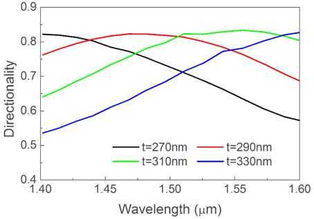
From the optimization process, we found that the radiation directivity is quite sensitive to the waveguide thickness of the ring resonator and the total radiation efficiency strongly depends on the gap distance between the ring resonator and the straight waveguide. However, they have to be optimized simultaneously since the structural change of the ring resonator also affects the total radiation efficiency. So, to save calculation time, the optimization was performed in two steps. First, we performed the optimization of the ring resonator structure including top gratings without the input waveguide. For this, we used a modal source located in the waveguide core of the ring resonator and performed the PSO [11] to maximize the vertical radiation. Then, using the resulting ring resonator structure, we performed optimization of the whole structure with the input wave-guide to maximize the radiation directivity and the total radiation efficiency simultaneously. In the second process, the ring resonator structure was also reoptimized. Figure 2 shows the radiation directivity of the ring resonator for the various waveguide thicknesses (t) with other parameters fixed close to the optimal parameters obtained in the first optimization process. As mentioned earlier, the radiation directivity of the ring resonator with the top gratings shows strong dependence on the waveguide thickness.
The final optimized design parameters of our OAM generator are as follows: ring radius R = 3.9 µm, number of grating n = 41, grating thickness tg = 59.76 nm, grating fill factor, which is the ratio between the grating’s width and the period, FF = 0.1, waveguide thickness t = 310 nm, waveguide width w = 480 nm, and the distance between the ring and the waveguide d = 100 nm. The device is designed to operate at a wavelength around 1.5 µm. In both devices, the waveguide is made of Si (nSi = 3.4) embedded in SiO2 (nSiO2 = 1.45). To generate OAM properly, the designed device should satisfy the phase matching condition, which is given by [3]
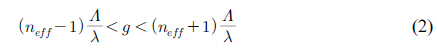
where neff is the effective index of the whispering gallery mode, Λ is the grating period, λ is the free space wave-length, and g is an integer. In our device, neff is around 2.4, Λ is around 0.6 µm, and λ is around 1.55 µm, hence 0.542 < g < 1.316. Because g can only take integer values, the only possible value of g is 1, and the phase matching condition is satisfied.
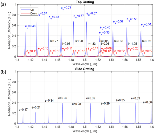
In Fig. 3, we show the simulated performance of our proposed top-grating structure compared to the side-grating structure using the FDTD method. To numerically calculate the peak upward and the downward radiation efficiencies, which are denoted as eu and ed, respectively, and defined as a percentage of the input energy at resonance, field monitors were located at the heights of z = +1 µm for eu and z = -1 µm for ed. In the case of the side-grating, e represents the peak radiation efficiency at resonance for both upward and downward radiation. The optimization of the structural parameters of the side-grating device has not been carried out in this work, and the parameters given in [3] were adopted instead. Since the device with the side-grating was designed for a transverse electric (TE) polarized input light [3], a TE polarized modal source was used in our calculation of the side-grating case. At most of the resonance wavelengths, the upward radiation efficiencies (eu) of the top-grating case exceed 50%, which is the theoretical limit of the side-grating case, and the highest value is about 78%. On the other hand, the highest radiation efficiency of the side-grating case is about 39%. In the top-grating case, the split at the wavelength of around 1.52 µm (l = 0 mode) was due to whispering gallery (WG) mode degeneracy caused by a counter rotating WG mode which was caused by Bragg reflection of the main WG mode. Note that upward and downward radiation efficiencies do not add up to 100%. That is due to the fact that a small percentage of the scattered energy is oriented sideway due to the nature of scattering, which does not contribute to the useful radiation of the vortex beam.
To confirm the generation of OAM by our device, we numerically calculated the total OAM carried per photon for each vortex beam generated through a surface parallel to the device, using the optical angular momentum flux method [13]. We have the total OAM carried per photon:
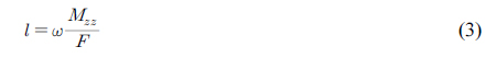
where ω is the angular frequency, F is the energy flux and Mzz is the total angular momentum flux through a plane perpendicular to the propagation direction z. The energy flux through a surface is given by
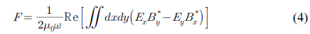
and the angular momentum flux through a surface is given by
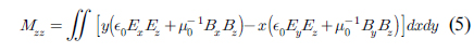
where Ei and Bi are the complex electric and magnetic fields, respectively. In our calculation, the surfaces used to calculate the OAM flux is 1 µm away from the device. The calculated OAM per photon for each resonant mode was also shown in Fig. 3, which is reasonably close to the theoretical topological charge number
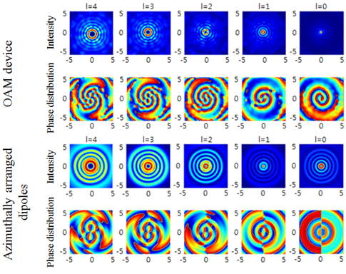
To further confirm the correct generation of OAM carrying beam, in Fig. 4, we compared the intensity and the phase profiles of the generated beam to those of a circular array of azimuthally polarized dipoles with proper phase shifts, which was confirmed to carry OAM. The number of dipoles is equal to the number of grating elements in our device. This corresponds to replacing each grating element with an ideal radiation source, which is similar to the process carried out to test the operation principle of the side-grating based OAM generator in [3]. The phase difference between adjacent dipoles is set to be 2πl/41 for a topological charge of
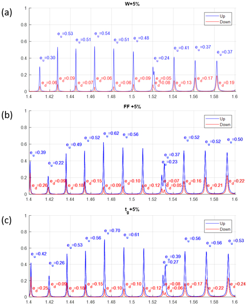
We have also analyzed the sensitivity of our device performance to certain design parameters that are relatively prone to fabrication error, namely the ring width
We have demonstrated a simple method to improve the emission efficiency of the compact integrated whispering gallery mode-based OAM vortex beam generator. In the designed OAM generator, upward radiation efficiency up to 78% was achieved. We have also numerically calculated the total orbital angular momentum carried by several OAM vortex beams, which were reasonably close to the predicted numbers. We believe the more than two-fold improvement in efficiency of a compact integrated OAM beam generator would in turn improve the efficiency of many quantum communication and single photon generating applications.

![(a) Side-grating-assisted ring resonator-based OAM generator, (b) our proposed top-grating assisted ring resonator- based OAM generator. The structural parameters of our OAM generator: R = 3.9 μm, tg = 59.76 nm, t = 310 nm, w = 480 nm, d = 100 nm, grating fill factor FF = 0.1, and number of grating n = 41. The structural parameters of the device in (a) are the same as given in [3]. In both devices, the waveguide is made of Si (nSi = 3.4) embedded in SiO2 (nSiO2 = 1.45).](http://oak.go.kr/repository/journal/22315/KGHHD@_2019_v3n4_292_f001.jpg)


![Amplitude and phase profiles of the generated OAM beam of our proposed structure compared to those of an array of azimuthally arranged dipoles with corresponding phase shift. The l number indicated was given by the formula l = p - q [3].](http://oak.go.kr/repository/journal/22315/KGHHD@_2019_v3n4_292_f004.jpg)