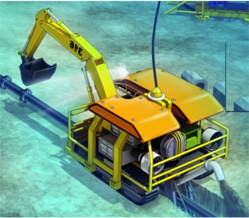
The real-time 3D reconstruction of underwater surfaces has become an important issue in applications like underwater environment inspection, underwater vehicle and robot navigation, and other multi-purpose underwater monitoring applications. This paper specifically focuses on the advantages of the real-time 3D reconstruction of an underwater environment for an underwater construction robot, as shown in Fig. 1. These advantages include obstacle avoidance by the recognition of the underwater scene topography, localization for a remotely operated vehicle (ROV) or an autonomous underwater vehicle (AUV) by matching given large 3D geometric information to increase the operation automation, and the intuitive perception of underwater environments for an ROV operator.
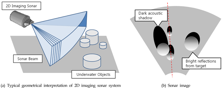
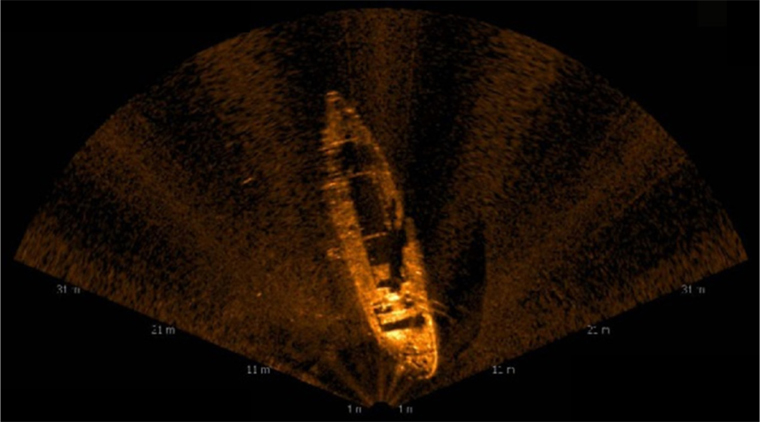
For ground vehicles, the 3D surface reconstruction method has been successfully applied in recent years. However, some problems remain unsolved for underwater vehicles, mainly because of the challenges of underwater environments. One of the most difficult peculiarities is unexpected turbidity, which makes it difficult to use an optical camera or a laser scanner because the field of view (FOV) of these sensors is dramatically decreased. Thus, imaging sonar sensors, which produce images by correcting the reflected sound intensity of acoustic beam pulses from underwater objects, have emerged as a possible alternative, because they are not affected by the turbidity. Fig. 2 shows a real underwater image captured by a 2D imaging sonar.
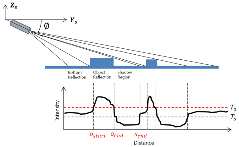
However, obtaining 3D information and clues from 2D sonar images is still challenging. In this paper, we first concentrate on the physical relationship between the sonar intensity data, which follow Lambert's law, and the scene topography (Aykin and Negahdaripour, 2012). The reflected sonar intensities differ with the angle of reflection, which is a key to estimating the topography. Second, we focus on the acoustic shadows that appear behind objects placed on the sea floor surface. For the same distance, the length of the shadow depends on the elevation of the scene. Hence, these shadows can be important visual clues in 2D imaging sonar imagery to determine the volume and edge boundaries of objects.
Therefore, the proposed real-time 3D reconstruction method first finds object-shadow pairs in the sequenced sonar images by analyzing the reflected sonar intensity pattern. Then, elevation information is computed using Lambert's reflection law and the length of the shadows. We evaluate the real-time 3D reconstruction method using real underwater environments. Experimental results are shown to appraise the performance of the method. Additionally, with the utilization of ROVs, the contour and texture image mapping results from the obtained 3D reconstruction results are presented as applications.
This paper is structured as follows: the related works are explained in section 2. Section 3 describes the data acquisition with the 2D imaging sonar. In section 4, we describe the underwater structure surface 3D reconstruction scheme, and then show the experimental results in section 5. Finally, in section 6, we close this paper with some conclusions and a discussion of future work.
The real-time underwater structure surface 3D reconstruction problem has been intensively studied for the last decade. There are several different types of sensors that have been applied, and each sensor has merits and demerits. Optical vision sensors have comparatively low prices, but do not provide 3D information. However, 3D information can be computed using vision-based 3D reconstruction techniques like stereo vision, structure from motion (SFM), and visual simultaneous localization and mapping (SLAM) (Brandou et al., 2007; Beall et al., 2010; Pizarro et al., 2004; Negahdaripour and Sarafraz, 2014). Although these techniques have made progress in ground vehicle and robotics applications, they have not been efficiently applied to underwater vehicles because of the challenging conditions of underwater environments such as the unexpected turbidity and light sources. The turbidity causes the FOV of the optical sensors to shorten, which causes difficulties in extracting features from images. In addition, a laser-based structured light system provides high-resolution 3D reconstruction results, but has the same problems with turbidity (Massot-Campos and Oliver-Codina, 2014). Thus, these kinds of optical vision-based sensors have an inherent limitation in underwater environments.
To solve this problem, acoustic device-based 3D reconstruction schemes have been studied to replace optical vision sensors. A multibeam scanning sonar captures 3D point cloud data similar to a topographic laser scanner (Papadopoulos et al., 2011; Coiras et al., 2007). These sensors provide high-resolution 3D reconstructed data, but need additional mechanical systems such as a pan & tilt device, which makes the sensors more expensive. Moreover, the 3D data provided are not real-time because these need a certain amount of time to scan the surroundings. A 3D imaging sonar captures a 3D point cloud in real-time without any additional device (Hansen and Andersen, 1993; Hansen and Andersen, 1996). However, its relatively low resolution and high cost are the primary drawbacks.
In order to overcome these drawbacks and meet the requirements for real-time 3D reconstruction, a 2D forward looking imaging sonar has been applied in recent years to underwater vehicle and robotics applications. Indeed, extracting 3D information from 2D images is challenging, but it has been made possible using the geometry and sonar intensity data relationship (Aykin and Negahdaripour, 2012), which inspired this study.
3. Data Acquisition with 2D Imaging Sonar
As shown in Fig. 3, acoustic pressure waves induced by the transmitters of an imaging sonar propagate and are reflected by the underwater structure surfaces, and the 2D imaging sonar collects these reflected echoes. The 2D imaging sonar discussed here is a BlueView P-900 (Teledyne BlueView, 2015). The P-900 has a range of 2–60 m, and 512 beams (beam width: 1° × 20°, spacing: 0.18°) are formed. The system offers 512 × 1160 images, where each pixel displays the reflection intensity for spots with the same distance, without elevation information.
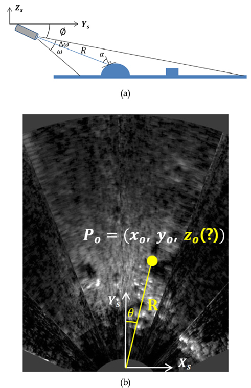
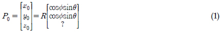
3.2 Coordinate System of Sonar
Equation (1) derives the 2D imaging sonar coordinate system by applying Cartesian coordinates (

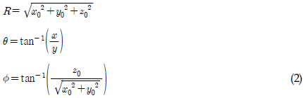
Equation (2) shows the method used to compute the spherical coordinates (

3.3 Object and Shadow Detection
As previously explained, the reflected sonar intensities depend on the angles of the reflecting surfaces of objects, which means it has a strong relationship with the shape of the objects. In addition, the shadow depends on the height of the object. Moreover, these shadows play an important role in 2D imaging sonar imagery to determine the volume and edge boundaries of objects. Thus, correctly detecting an object and its shadow is a crucial factor for 3D reconstruction from 2D sonar images.
i. Estimation of Sea Floor Surface:
To define an object, this paper applies a machine learning algorithm. Indeed, the sonar intensity data follow Lambert's reflection law, as seen in Eq. (3).

where
ii. Feature Detection:
Once the sea floor is defined, then the thresholds of the object
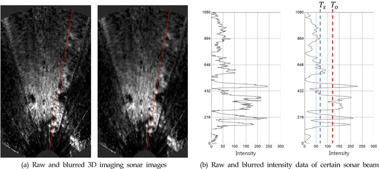
Fig. 6 shows an actual 2D imaging sonar image with the intensity data of a certain sonar beam. In actuality, the raw data are too noisy to accurately detect objects. Thus, a preprocessing process is needed such as the Gaussian image blur. As shown in Fig. 6 (b), the intensity data become clear after the image blur process, and
4. Sonar Surface 3D Reconstruction
In order to extract 3D information from 2D sonar images, this paper defines the constraint conditions as follows:
In the 3D reconstruction of reflectable materials, a smooth steel-like surface is not detected by 2D imaging sonar. Thus, that kind of object is not applied. The 2D imaging sonar needs to be placed deep enough that it is free from disturbances from sea surface reflections. The reflections from underwater objects follow Lambert's law.
4.2 Surface Elevation Computation Scheme
After detecting objects and shadows from the 2D sonar intensity data, the 3D reconstruction procedure is as follows:
ⅰ. Detect objects and shadows based on T0 and Ts ⅱ. Find Ostart, Oend, and Send from the 2D sonar images ⅲ. Compute the elevation using Equation (4)
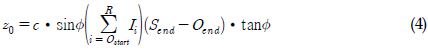
where
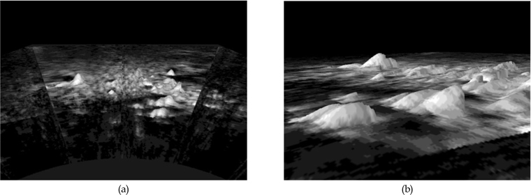
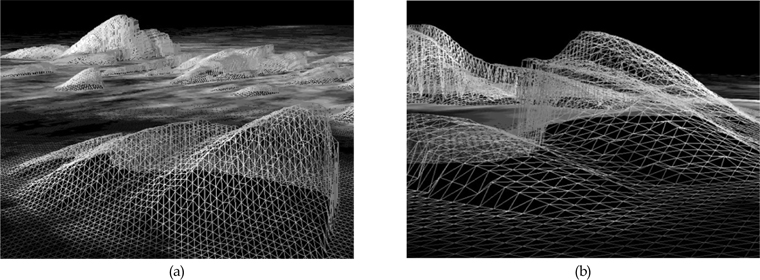
Fig. 7 shows the results of the 3D reconstruction of a real underwater structure surface. The results are obtained by applying the images obtained from the multibeam imaging sonar as the texture on the 3D mesh results, which are shown in Fig. 8.
5.2 Contour and Texture Mapping
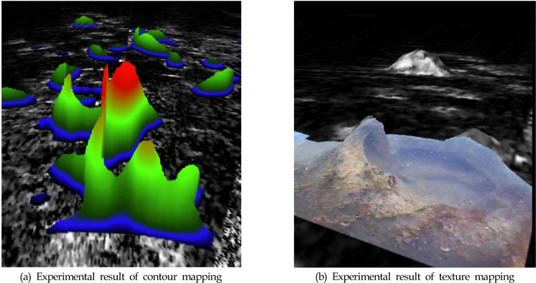
Obstacle avoidance is a good application of the 3D reconstruction for an ROV. Therefore, the intuitive perception of the height of an underwater structure is very important for an operator. Fig. 9 (a) can be useful for this. Moreover, in collaboration with an optical camera image, texture mapping on the 3D reconstruction results is possible, as a result of the intuitive underwater scene perception (see Fig. 9 (b)). In this experiment, an ROV was utilized to obtain optical images, which are applied as the texture on the 3D reconstruction result, since the FOV of the optical camera was relatively short compared to the multibeam imaging sonar.
In this paper, we demonstrated that 3D information can be extracted 2D imaging sonar data. This is achieved by detecting the objects and shadows from the sonar intensity data. The 3D information could be obtained using the presented elevation computing scheme. This scheme could be applied to a ROV or an AUV by offering the 3D map with contour and texture. Moreover, the accuracy of this scheme will be further examined, and applied to large 3D mapping using a tracking and mapping method for the localization of ROVs and AUVs.