Terahertz (THz) waves, which span the frequencies from 0.1 THz to 10 THz, lie in the frequency gap between the infrared and microwave and have received considerable attention during the past decades [1]. One of the most important devices in THz applications is the bandpass filter, which can be widely applied in imaging, spectroscopy, molecular sensing, security, drug identification, or other systems [2]. Most investigators have focused on the design and fabrication of terahertz filters with a single resonant frequency [3-6]. Nowadays, for spectroscopic applications and astronomical detection, multiple band terahertz bandpass filters are required [7]. On the other hand, the recent trend in terahertz communication systems is to utilize multiple frequency bands and multiple beams to significantly increase the communication capacity [8]. This provides an economical means of developing multi-mission systems and creates a potential demand for multi-band terahertz filters.
Multi-band bandpass filters have gained great attention in wireless communication systems [9-12]. However, in the terahertz frequency range, articles concerning multi or dual-band bandpass filters are still limited. A metal-dielectric dual-band filter consisting of double four-legged loaded slots with different dimensions in one unit cell was investigated theoretically, it was found that the resonant frequencies occurred at 0.183 and 0.22 THz [13], a dual-band terahertz bandpass filter centered at 0.97 THz and 1.37 THz was simulated by exciting multiple resonances of a metal-dielectric-metal structure, both the passbands show high transmissions up to 90% [14]. Recently, photonic crystal dual-mode dual-band terahertz bandpass filters have been designed. They are formed by a point defect microcavity that is equipped with one large and three smaller auxiliary perturbation rods [15]. A metal-dielectric-metal (MDM) sandwich structure consisting of periodic square close ring arrays on both sides of a flexible dielectric substrate has been numerically studied, the designed structure exhibits a multiband transmission with low average insertion loss, steep skirts and high out-of-band rejection [16]. For the terahertz multi-band bandpass filters reported above [13-16], no further experimental demonstration was carried out.
By perforating metal films with three different geometric shapes, terahertz multi-band filters with strong transmission peaks have been manufactured and measured, and it has also been demonstrated that near-unity transmittance can be obtained at desired terahertz frequencies in plasmonic metamaterials through the shape resonance [17]. By deposition of identical metallic frequency selective surface layers on the upper and lower sides of a quartz crystal to form the metal-dielectric-metal sandwiched structure, second-order bandpass THz filters have been fabricated [18, 19], however, the fabrication processes of these metal-dielectric-metal filters are relatively complicated compared with the metal-dielectric or single-layer metal structure. Multi-band terahertz filters consisting of two and three concentric rings complementary structure have been demonstrated based on metal-dielectric structures, results found this structure showed great insensitivity to incidence angles [20].
In this paper, dual-band terahertz filters are designed based on frequency selective surfaces. Three samples are fabricated by perforating two different rectangular holes in one unit with laser in 100 μm-thick molybdenum. Experimental results measured by a THz time-domain spectroscopy system show agreement with simulation results. In contrast with most commonly used metal-dielectric structure or metal-dielectric-metal sandwiched structures, the dual-band filters are designed with only one metal layer, which makes fabrication easy and cost low. In addition, the design process is straightforward and simple according to the physical concept and some formulas. Due to the weak coupling between the two rectangular holes in the unit cell, good selectivity performance can be easily achieved both in the lower and higher bands by tuning dimensions of the two slots. Physical mechanisms of the dual-band resonant responses are also clarified.
II. SIMULATIONS AND DISCUSSIONS
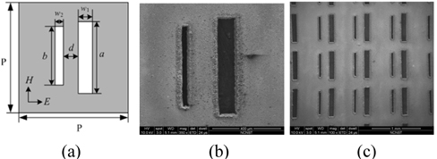
A Frequency Selective Surface (FSS) is a periodic assembly of one- or two-dimensional resonant structures that exhibits bandpass or bandstop filtering [21-23]. A common class of bandpass FSS can be constructed by placing a periodic array of conducting elements on a dielectric substrate or slots in a conducting surface. Figure 1(a) shows the top view of the unit cell of the dual band FSS filter, the dimensions of the design are P = 770 μm, a = 590 μm, b = 500 μm, w1 = 105 μm, w2 = 35 μm, and d = 230 μm. Fig. 1(b) shows the scanning electron micrograph of the fabricated structure. This designed filter can be easily constructed by perforating a periodic array of air slots in 100 μm-thick molybdenum (conductivity σ = 1.76 × 10⁷ S/m) with a laser (LPKF ProtoMat S43). For the rectangular cell in the frequency selective surface, the resonant frequency can be nearly calculated by the equation [24]:
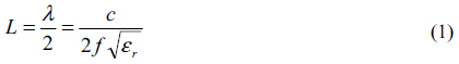
where
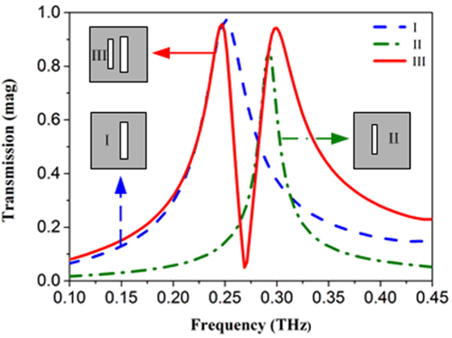
The dual band filter can be modeled as an infinite array in CST Microwave software by utilizing full Floquent mode implementation to simulate a single unit cell of the FSS. For the electric field perpendicular to the long edges of the resonators as stated in Fig. 1(a), the transmission can be obtained from the S-parameters. Three differently configured FSS filters, as shown in the inserts to Fig. 2, are simulated. All of them exhibit band pass characteristics. There is only a single-band in the frequency from 0.1 THz to 0.45 THz both for configuration I or configuration II. For configuration I, the resonant peak occurs at 0.252 THz with the maximum transmission 97% and the 3 dB relative bandwidth 14%. For configuration II, the resonant peaks occur at 0.294 THz with the maximum transmission 87% and the 3 dB relative bandwidth 4%. The simulated resonant peaks at 0.252 THz and 0.294 THz for the configurations I and II are in accordance with the theoretical calculation values 0.254 THz and 0.3 THz, respectively.
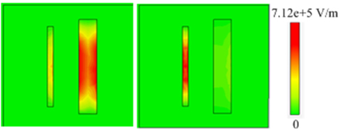
As is shown in configuration III, deploying the two types of resonators (configuration I or configuration II) in one unit cell results in a dual-band, a superposition of configurations I and II. Two resonances occur at 0.247 THz and 0.3 THz, respectively, which are in accordance with the theoretical results 0.254 THz and 0.3 THz. For the first band, the maximum transmission is 96% with the 3 dB relative bandwidth 9%, and for the second band, the maximum transmission is 94% with the 3 dB relative bandwidth 10%. However, the central frequency, the maximum transmission and the 3dB relative bandwidth of configuration III do not complete correspond to that of configurations I and II due to the coupling among the neighboring resonators. To further clarify the physical mechanism of the two pass bands, electric field distribution diagrams at the resonant frequencies of 0.247 THz and 0.3 THz are given Fig. 3, it is observed that the electric field resonance occurs in the long rectangular hole at 0.247 THz, and the electric field resonance occurs in the short rectangular hole at 0.3 THz, Outside the two slots, electric field values are very weak. Consequently, the two pass bands arise from a superposition of two different neighboring holes.
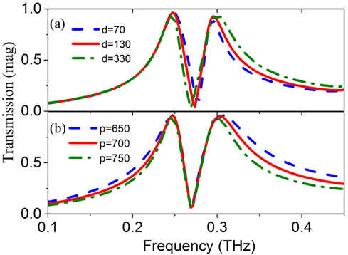
The characteristics of the dual-band filter actually depend on its geometrical parameters. Figure 4 shows the influence of distance d and period length p on the transmittance spectra while the remaining parameters are fixed. As shown in Fig. 4(a), on increasing the distance between the two rectangular holes from 70 μm to 330 μm, the left sides of the two transmission bands have no change. Location of the first band shifts to the low frequency with a small decrement of 0.001 THz, and location of the second band shifts to the high frequency with an increment of 0.002 THz. Therefore, distance between the holes has small influence on the transmission of the dual-band filter. In Fig. 4(b), as the periodic length varies from 650 μm to 750 μm, bandwidths of the two bands decrease. Location of the first band shifts to the high frequency with an increment of 0.001 THz, while location of the second band shifts to the low frequency with a decrement of 0.002 THz.
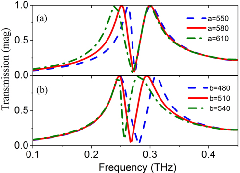
Figure 5 shows the transmittance spectra for various lengths of large hole a and small hole b. As shown in Fig. 5(a), increasing length of the large hole causes an obvious red shift in the transmission peaks in the first band, while there is little shift in the second band. This result can be explained from the resonance frequency of the first band in Eq. (1). Because the resonance frequency is mainly dependent on size a, i.e., f1=c/2a. For a=550, 580 and 610 μm, the simulated transmission peaks f1 are 0.261, 0.251 and 0.240 THz, respectively, which are nearly corresponding with the calculated results of 0.273, 0.259 and 0.246 THz, respectively. On the other hand, when slot length a increases, both the peaks and the bandwidths of the first band increase because more waves near the resonant frequency can be transmitted through the filter. In Fig. 5(b), the transmission peaks in the second band decrease with increasing b, because the resonance frequency is dependent on size b, i.e., f2=c/2b. For b=480, 510 and 540 μm, the simulated transmission peaks are 0.307, 0.291 and 0.278 THz, respectively, which are again in good agreement with the calculated results of 0.313, 0.294 and 0.278 THz, respectively.
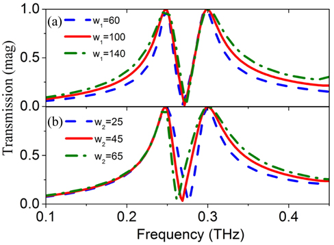
Figure 6 shows the transmittance spectra for various values of the slot widths w1 and w2, while the remaining parameters are fixed. In Fig. 6(a), as width of the large slot w1 increases from 60 to 140 μm, both the transmission peaks and bandwidths of the two bands increase. In Fig. 6(b), as width of the small slot w2 increases from 25 to 65 μm, the transmission peaks of the two bands tend to increase. Bandwidth of the second band increases, while bandwidth of the first band decreases. Those results in Fig. 4, Fig. 5 and Fig. 6 confirm that the location and bandwidth of the two bands can be easily tuned by parameters of the filters. Transmission locations of the two bands are mainly determined by the length a and b of the two rectangular holes, while the bandwidths are influenced by all parameters.
III. EXPERIMENTS AND DISCUSSIONS
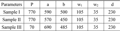
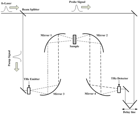
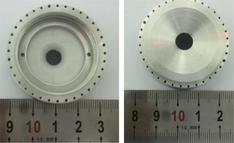
In this work, three samples are fabricated by perforating a 100 μm-thick molybdenum layer with a periodic array of two rectangular holes with a laser (LPKF ProtoMat S43). Table 1 shows the dimensions of the samples. All the samples have the same period P, width w1, w2 and distance d, but with different rectangular lengths a and b. Each fabricated sample has a 25 × 25 square array and a very good uniformity was achieved across the 20×20 mm region. Terahertz time-domain-spectroscopy (THz-TDS) was used to characterize the dual-band responses. The functional frequency region of THz-TDS is 0.05-2.5 THz in this case. Figure 7 shows the diagram of the THz-TDS setup. In brief, the output of a mode-locked Ti-sapphire (Spectra Physics Mai Tai HP), with pulse duration of 70 fs, centered wavelength at 800 nm, and repetition rate of 82 MHz, is used to generate and detect the terahertz transient. The THz pulses are generated from a low-temperature growth GaAs photoconductive antenna, and a ZnTe crystal with (110) orientation is used as the THz wave detector. To fix the 100-micronthick Mo filter for testing, a circular aperture is used. Figure 8(a) and (b) show the back view and front view, respectively, of the circular aperture used to fix a sample in the center.
[TABLE 1.] Geometric parameters of the fabricated dual-band filters samples (μm)

Geometric parameters of the fabricated dual-band filters samples (μm)
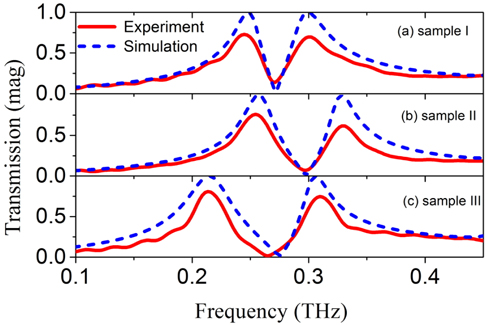
Figure 9 shows the THz wave transmittance characteristics of the three samples at frequencies from 0.1 to 0.45 THz, where the solid and dashed lines represent the measured and simulated results, respectively. The measured results of sample I show transmittance peaks of 73% at 0.245 THz and 71% at 0.30 THz, while the simulated results show transmittance peaks of 100% and 96% at 0.249 THz and 0.3 THz, respectively. For sample II, the measured results show transmittance peaks of 76% at 0.249 THz and 63% at 0.33 THz, while the simulated results show transmittance peaks of 97% at 0.26 THz and 99% at 0.33 THz, respectively. For sample III, the measured results show transmittance peaks of 80% at 0.214 THz and 75% at 0.31 THz, while the simulated results show transmittance peaks of 100% and 96% at 0.214 THz and 0.3 THz, respectively.
The measured transmission curves match the simulated curves, however, there is a slight shift in the resonance frequencies caused by the dimension error processing. On the other hand, the larger loss of the peaks in the measurement may be attributed to the roughness of the fabricated samples. Roughness of the metal can’t be set in the CST software. But as we know roughness of metal affects conductivity of the metal. By simulation, we found that the larger the conductivity of the metal, the higher transmission of the filter. Making the samples smooth or using metals with higher conductivity may increase transmission of the two bands. In addition, the periodic boundary conditions approximate an infinite array in the simulations, while the experimental results were measured with limited periods, this discrepancy will also affect the results.
In conclusion, we have designed and fabricated dual-band FSS filters in the terahertz band by perforating two different sizes of rectangular slots with laser in Mo. Experimental measurements demonstrate good agreement with simulation results. These structures have good selectivity performance both in the lower and higher bands by tuning parameters of the two neighboring rectangular holes. Transmission locations of the two bands are mainly determined by the lengths a and b of the two rectangular holes, while their bandwidths are influenced by all parameters. As the design process is straightforward, the resonant peaks of the two bands can be simply estimated according to their physical concepts and the corresponding formulas. Finally, the designed single-layer frequency selective surface filters in the terahertz band also have great advantages of easy fabrication and low cost. The encouraging results afforded by this designed filter could find its applications in dual-band sensors, THz communication systems and other emerging THz technologies.