Visible light communication (VLC) systems rely upon visible radiation from light emitting diodes (LEDs) to convey information in a wireless environment. The main feature of VLC lies in data transmission ability via lighting units typically installed to provide illumination indoors. VLC can be considered a strong contender for future indoor wireless communications with high data rate and high performance [1].
Multiple-input multiple-output (MIMO) transmission has become attractive because it can enhance the capacity of a VLC system without requiring any increase in transmission bandwidth or power. Researchers have demonstrated optical MIMO techniques based on nonimaging and imaging approaches to achieve high data rates [2, 3]. A 4×4 MIMO VLC scheme with a commercial charge-coupled device (CCD) as an image sensor receiver was demonstrated in [4]. An experimental 4×4 MIMO VLC achieved a data rate of 10 Gbit/s using a vertical cavity surface emitter laser (VCSEL) [5]. MIMO techniques coupled with OFDM and equalization [6], spatial modulation [7], and spatial multiplexing [8] have been proposed in the literature. In the MIMO VLC, phosphorcoated white LEDs are predominantly employed for transmission [2-4, 6-8], because these LEDs are popular, cheap, and easy to manufacture. Unlike these studies, a color-clustered MIMO technique using RGB LEDs was also proposed [9]. The color-clustered scheme for multiuser data transmission using RGB LEDs was first proposed in [10], while the study in [11] enhanced this strategy for a color-clustered bidirectional multiuser scheme, based on an efficient frame structure.
Although the aforementioned MIMO techniques present efficient schemes to achieve high data rates, the high performance in terms of BER was achieved at the expense of signal to noise ratio (SNR). These MIMO techniques can be strengthened by incorporating diversity benefits in the transmitter, thus achieving high performance at relatively low SNR values. In a diversity technique, multiple copies of the original data stream are transmitted via separate transmission paths. To achieve the diversity benefit, it is known that these multiple transmissions must undergo independent fading in the context of time and/or frequency. In this paper, we consider a combined time and frequency diversity scheme based on the color-clustering method. In particular, we investigate an efficient time-frequency high-speed and high-performance color-clustered MIMO VLC based on blue, cyan, yellow, and red (BCYR) LEDs, for a high-performance and high-speed MIMO VLC system. The use of the BCYR LEDs was first reported for a four-color CSK modulation scheme in [12]. The CSK scheme utilized a complex maximum likelihood (ML) detection technique, and a BER of 10-5 was achieved at an
To achieve high-speed data transmission, LEDs with a high 3 dB modulation bandwidth [13] can be utilized, which can also fulfill the illumination requirements. The 3 dB modulation bandwidth of an LED can be defined as the range of frequencies used to modulate the drive current for which the detected optical power drops by 3 dB, with respect to the optical power emitted with DC drive current. It is found that LEDs can theoretically have a 3 dB bandwidth of up to 2 GHz [13, 14]. Additionally, an LED with an optical modulation bandwidth of 1.7 GHz has also been proposed [15].
While achieving high-speed data transmission, we consider the time-frequency color-cluster (TFCC) scheme, to significantly improve the performance of the proposed VLC. In TFCC, the original data and two delayed versions of the data are multiplied by orthogonal frequencies, then transmitted using a specific color of the BCYR LED. It is important to note that the orthogonal frequency employed provides a significant performance improvement in the form of
The proposed scheme is focused on addressing two of the most fundamental issues in VLCs: high data speed and high performance. Although the BCYR LEDs and diversity schemes have already been introduced in the literature, these techniques have been unable to deliver a high-speed, high-performance VLC system. Based on the BCYR LEDs and the unique double diversity techniques, however, the proposed scheme demonstrates that it can offer a data rate of 2 Gbit/s and a bit error rate of 4×10⁻⁵ at an
The remainder of the paper is organized as follows: Section 2 describes the proposed scheme, while the discussion of the theoretical analysis is presented in Section 3, and simulation results are shown in Section 4. Conclusions are drawn in Section 5.
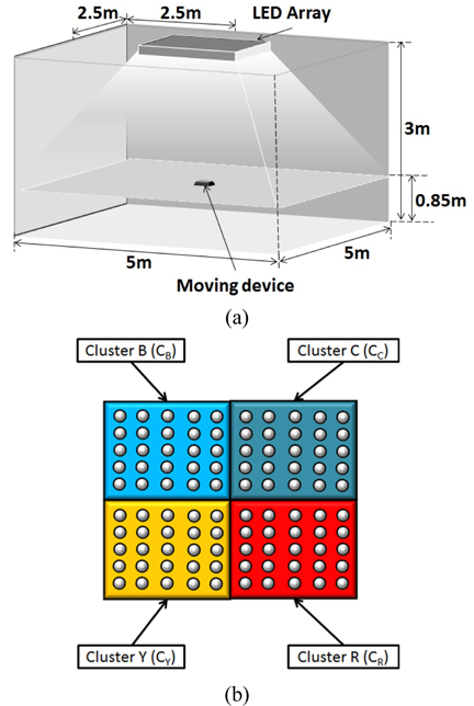
A typical indoor environment for the proposed scheme, with room dimensions of 5 m × 5 m × 3 m (length × width × height), is shown in Fig. 1(a). The proposed scheme consists of four different color clusters in blue, cyan, yellow, and red colors, exploiting commercially available BCYR LEDs. Recognizing the fact that VLC systems in an indoor environment should fulfill illumination functionality besides providing wireless data communication, we placed 25 BCYR LEDs in each color cluster, to ensure the proper brightness level defined by ISO [17]. In other words, a total of 100 BCYR LEDs are installed in the ceiling. Figure 1(b) shows the four BCYR LED color clusters. To mitigate intersymbol interference (ISI) between LEDs, the LEDs are suitably separated. It is important to note that since multi- color LEDs are available commercially [18], the BCYR LEDs employed in the present study can be considered by mixing colors in a quadrilateral constellation shape of CIE 1931 [12].
The detailed description of the scheme, in terms of the functionalities of transmitter and receiver, is provided below.
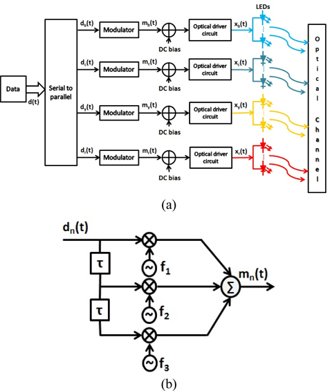
Figure 2(a) depicts the transmitter structure, composed of the modulators and the BCYR LEDs. At the transmitter, an input binary sequence is first divided into four parallel streams
It is important to note that the amount of delay in the delayed paths needs to be determined in such a way that the paths undergo independent transmission over the optical channel, to exploit the diversity effect for improved performance. In a typical indoor environment, the signal transmitted along the direct path and also that from the first reflection reach the receiver within 2 ns [17]. As a result, we set the value of the delay τ to 2 ns. Also, with the two delayed data paths employed, the symbol duration
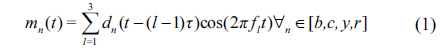
where
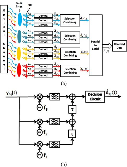
The receiver structure for the proposed scheme is shown in Fig. 3. The four receivers installed at the receiving end consist of three PDs, each receiver equipped with a color filter to filter out the data transmitted from other clusters. The signal
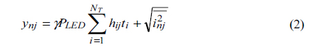
where
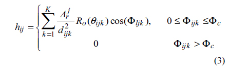
where is the receiver collection area for the

where
The received signal from each PD is passed through the coherent demodulator as shown in Fig. 3(b). It can be observed from Fig. 3(b) that
The luminance expresses the brightness of an illuminated surface. It is assumed that the light intensity emitted from the source has a cosine dependence on the angle of emission with respect to the normal surface [17]. The luminous intensity at angle

A horizontal illuminance

where
The optical wireless channel is modeled as additive white Gaussian noise (AWGN) and is expressed as

where
3.3. Bit Error Rate and Maximum Achievable Data Rate
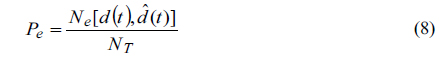
The bit error rate

where represents the number of bits in error between
For a given error rate
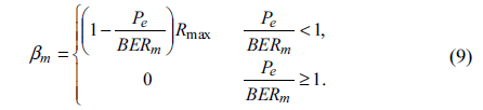
where
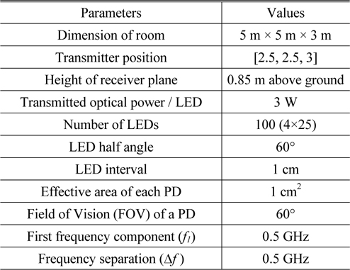
To evaluate the effectiveness of the proposed scheme, performance evaluation via computer simulations is performed using the parameters listed in Table 1.
[TABLE 1.] System simulation parameters

System simulation parameters
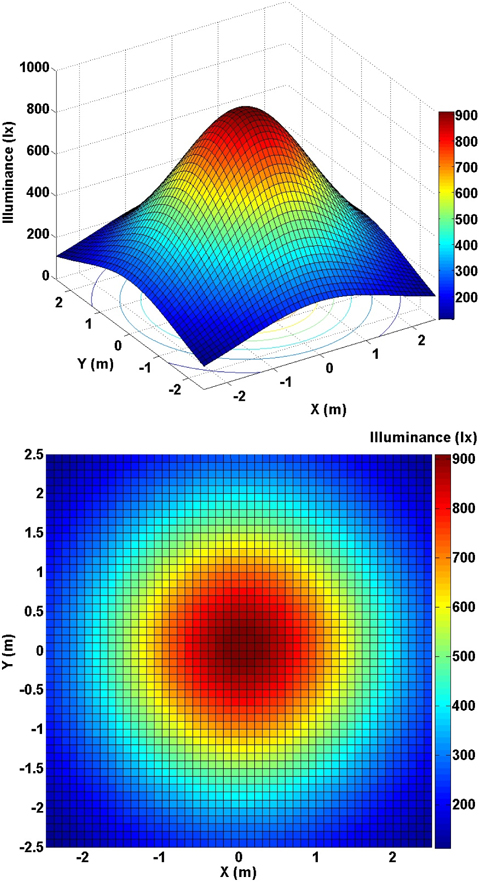
Figure 4 shows the illumination distribution results obtained from Eq. (6). According to the ISO standard [17], it can be said that the room is sufficiently illuminated at nearly all positions, with illuminance of 250 to 900 lx, except for the far corners of the room.
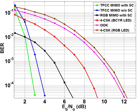
Simulation is performed under AWGN using Eq. (7). Figure 5 describes the bit error rate (BER) performance comparison of the proposed scheme to conventional transmission schemes reported in the VLC literature: the RGB MIMO scheme, BCYR LED (or RGB LED)-based 4-CSK, and OOK. For the MIMO schemes, we considered the SC combining technology. For a fair comparison to existing schemes, the simulations were performed while keeping the data rates for all schemes constant at 2 Gbps. In other words, the bit duration for each of the schemes is determined to limit the data rate to 2 Gbps. It can be observed from Fig. 5 that a BER of 4×10⁻⁵ is achieved at an
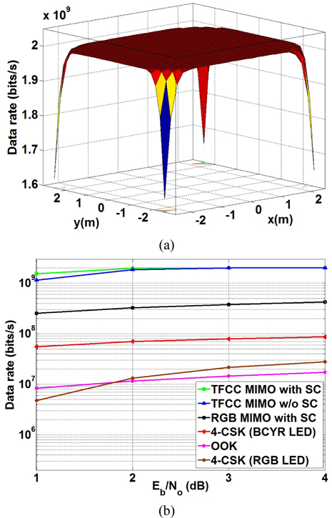
In addition to the BER performance analysis, it is worth investigating estimated data rates over the entire room in the assumed indoor environment (see Fig. 1(a)). Figure 6(a) shows the data rate distribution for the proposed scheme, at the reference BER value of 10-3. It was found that a data rate of 2 Gbit/s was achieved with the proposed scheme over most locations in the indoor environment, except for the far corners.
We have further analyzed the achievable data rates relative to the
A 2 Gbit/s VLC scheme using a novel time-frequency color-clustered MIMO based on BCYR LEDs is presented. The proposed scheme achieves a high-speed and high-performance VLC by exploiting the diversity gain (for high performance) and color-clustered multiplexing (for high speed) in the TFCC MIMO based on the BCYR LEDs. When compared to the most recent transmission schemes such as RGB MIMO VLC and 4-CSK (BCYR LEDs), it achieves gains of approximately 4 and 6 dB, respectively. In addition, the data rate comparison reveals that the proposed scheme attains the highest achievable rate among all other considered schemes. Therefore, the proposed high-speed and high-performance MIMO VLC can be considered a candidate for an efficient indoor VLC link.