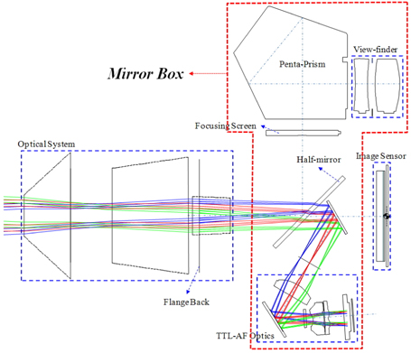
Although the existing compact camera market is declining as camera phones become more common, the lenses of camera phones cannot change their field angles nor generate out-of-focus photos due to their deep depths of field. For these reasons the market for interchangeable-lens cameras still exists, since such cameras allow photographers to take pictures at various field angles and to control the degree of focus of an image [1]. The key characteristics of interchangeable-lens cameras are that they exhibit no parallax, as the optical axes of the lens and view finder, coincide and that they employ mirror boxes instead. Such cameras are known as single-lens reflex (SLR) cameras [2]. Figure 1 shows a cross-section of an SLR camera, in which the mirror box consists of a view finder with a main mirror, a sub-mirror, an autofocus (AF) module, and a penta-prism [3].
Since SLR cameras have now become digitized, the term digital SLR (DSLR) is being used instead of SLR. Because of their mirror boxes, however, DSLR cameras not only are unfavorable for taking videos, but also are limited in terms of possible size and weight reduction of the main camera body. To solve these problems, interchangeablelens cameras without mirror boxes have recently been suggested and marketed by several companies. Interchangeable-lens cameras without mirror boxes are called compact-system cameras (CSCs), and many companies that market DSLR cameras sell CSCs as well [1].
In a DSLR camera, the AF system is embedded in the mirror box and AF is realized by shifting the AF lens to a certain position, after determining the distance to an object, by adjusting the difference between the points at which two beams of light from the object are detected on the AF sensor. This is called a phase-detection AF system [2, 4, 5]. In a CSC, on the other hand, the AF process is realized by shifting the AF lens incrementally by unit lengths, and a signal from the image sensor is detected to determine the contrast in the system. This is called a contrast AF system. Therefore, CSCs have the shortcoming of slower AF speeds than those of DSLR cameras, but they also have the advantage of greater AF precision. To improve the AF speed in a CSC, the drive motor of the AF lens must generate a higher torque, or the AF lens itself must be lighter. Another method to improve AF speed is to acquire signals more quickly at the image sensor, but this method should be investigated by electronics engineers rather than optics designers. Moreover, increasing the torque of the drive motor is also out of the scope of optical design. Therefore, in this report, we only propose a new optical design that yields more lightweight AF systems in CSCs.
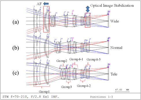
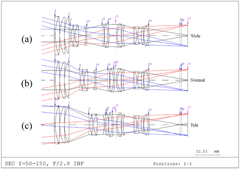
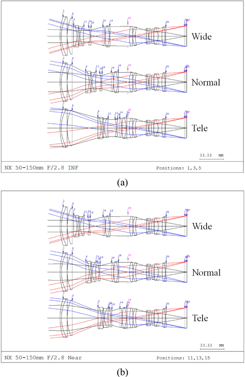
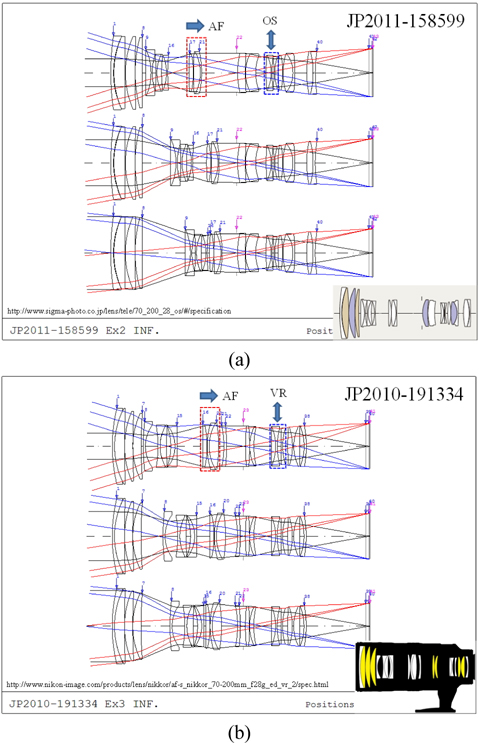
For this investigation, the optical system for a large telephoto zoom lens was designed with a half-field angle of 35°-12° and a fixed f/2.8, regardless of the field angle variation. Such a device would be a high-end product that would fully utilize companies’ research capabilities and manufacturing technologies. Figures 2(a) and (b) depict as examples the optical layouts of two products already released by the Japanese companies S [6, 7] and N [8, 9] respectively. In Fig. 2 the upper, middle, and lower configurations present respectively the wide, normal, and telephoto modes of these zoom lens systems. As shown in these images, the lens configurations of the actual products are almost the same as those in the patented cases, and the AF lenses are indicated in the corresponding patent plots. The figure also illustrates that the existing products generally use three Group 3 lenses to form the AF group. Previously, some products autofocused by moving a few of the Group 1 lenses that are fixed during zooming, so that the distance window could be easily realized [10]. This method, however, results in much heavier AF groups than those of the products shown in Fig. 2, requiring great power consumption to autofocus, in either CSCs or DSLR cameras. The optical systems in Fig. 2, of course, have lighter AF groups than those in cameras in which part of Group 1 is used for the AF process.
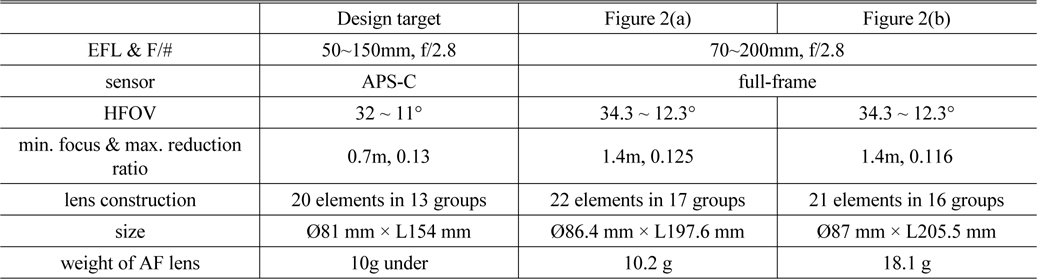
Figure 2 shows an optical system with a 36 mm × 24 mm sensor, which is the same size as the full-frame sensors used in 35 mm. If an Advanced Photo System, Type C (APS-C) sensor is used, the system in Fig. 2 can be scaled down. Even so, optical systems similar to those of Figs. 2(a) and 2(b) would weigh about 10.2 g and 18.1 g, respectively, at the effective diameter of lenses. When scaled down, however, the lenses might be too thin to fabricate, yet designing thicker lenses would cause the system to become heavier. It can therefore be assumed that the minimum AF group weight in a system such as those shown in Fig. 2 would be 10 g. Thus, a new optical system with an AF group lighter than those of the systems in Fig. 2 should be designed. In addition, the new system must employ a single lens in the AF group. Because utilizing a smaller-aperture lens would enable the system to be lighter, the AF process in the new system should be implemented by moving lenses with smaller apertures. The system must have the minimal lateral color and field curvature even after shifting the smallest-aperture lens, and the lateral color must also be corrected based on the final lens location, complicating the system design.
Furthermore, telephoto lenses with small field angles are greatly affected by hand blur. Therefore, a group of lenses for optical image stabilization (OIS) must be included, for which lightweight lenses would maximize OIS performance. Although three Group 4 lenses form each of the OIS groups in Fig. 2, in this paper we will discuss a system that yields the same OIS performance as do the groups in Fig. 2, but uses only two lenses. In short, we will present the basic design of a large telephoto zoom lens of acceptable optical performance, but with AF and OIS lens groups lighter than those of current cameras.
II. EXAMPLE OF A LARGE TELEPHOTO ZOOM LENS SYSTEM
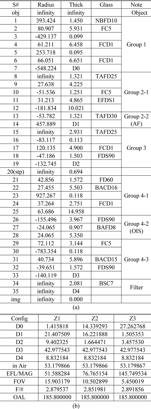
When the specifications of an optical system are set, the number of lens groups for initial use needs to be decided. Then each group should be designed with a refractive power that yields the effective focal lengths (EFLs) necessary for both wide and tele modes, considering the mechanical spacing of each group. The specifications of the optical system designed in this study, as well as those of the example systems in Fig. 2, are described in Table 1 and include the EFL, f-number (f/#), half field of view (HFOV), distance from the tip of the product on the object side to the mount, and weight of the AF lens as calculated based on the specific gravity of the material and the effective area of the lens in each patent case.

Specifications of large telephoto zoom lenses in our design system and of the examples in Fig. 2
To optically design the zoom lens as mentioned earlier, the refractive power of each group in the optical system described in Table 1 can be calculated using a Gaussian bracket so that each achieves the EFL necessary for wide and tele modes [11]. In practice, however, the design process is much faster if an existing, patented design is adjusted to generate a refractive power for each group that satisfies the required conditions, rather than determining the refractive power of each group independently. Of course it is possible to use the powerful optimization capabilities of optical design software to do this, but using such software introduces several problems when the design is to be optimized based on any desired first-order quantities, such as the EFL and magnification (MAG). Moreover, software methods are not recommended because they lack an understanding of the optical system. In this investigation, we designed an optical system by obtaining information about relevant patented designs and reconfiguring each lens group to obtain a refractive power that meets the chosen requirements. To design a system with different specifications, the identification of relevant patented cases would entirely depend on the designer’s capabilities, based on his or her experience rather than a particular theory.
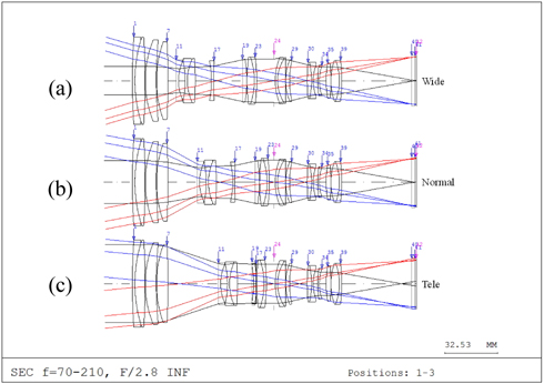
Fortunately, we were easily able to identify a patented system that could be modified to meet the requirements listed in Table 1. This system is shown in Fig. 3 and is also listed as Example 3 in Reference [12]. Figures 3(a), 3(b), and 3(c) present the optical layouts of the wide, normal, and tele modes respectively. The curvature, thickness or spacing, and refractive index of the case are specified in the corresponding patent [12].
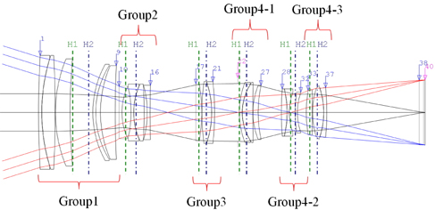
The optical system shown in Fig. 3 is composed of four main groups, as follows: Group 1 is divided into two subgroups, and the two rear lenses can be shifted forward to perform the AF process; Group 2 is a variator; Group 3 is a compensator; and Group 4 is a relay group, in which the three rear lenses are used to perform OIS [13]. This system was designed for use in a DSLR camera and facilitates distance-window implementation, because all of the AF group movements in relation to an object’s distance are the same, regardless of the system’s field angle [13]. However, the system’s AF group aperture is too large to be used in CSCs, as described in Part I of this paper. In addition, it is necessary to further reduce the weight of the OIS system, and to reduce the sizes and number of lenses.
First, we discuss the positioning of the OIS lens group in this system. The OIS lenses cannot be placed in a moving group, such as a variator or compensator, nor in a group having a large aperture, such as Group 1. Another possibility would be to use the last three lenses in Group 4, as shown in Fig. 3, but to replace them with smaller-aperture lenses, for weight reduction. Therefore, it would be preferable to use the fourth, fifth, and sixth lenses in Group 4 as the OIS lenses, which is how most optical companies choose to implement OIS. In this study, however, we adapt this method by choosing to use the middle lens group in Group 4 as the OIS group, and we use only two lenses, instead of three, to reduce the weight. The next step is to determine the configuration of the AF group. It is preferable to place the AF group in the smallest-aperture group, to further reduce the weight of the system. Since Group 2 has the smallest aperture, except for that of Group 4, adding a lens to Group 2 yields a new AF group configuration. In addition, a lens is removed from Group 1, reducing the number of lenses in this group to four, since it is not necessary to use all five lenses in Group 1 when the AF group is removed from Group 1. Although this system uses a full-frame image sensor, we design a small, deformed zoom lens system in this study, using a small APS-C digital image sensor instead of a full-frame image sensor, as described in Table 1, to reduce the product’s size.
III. POWER ARRANGEMENT OF EACH GROUP
Figure 4 presents the detailed optical layout of the wide mode of the system that was given as Example 3 in Reference 12 and was mentioned in Part II. In this figure, the lenses in each group are clearly illustrated and marked, and the dotted and the alternating dashed lines perpendicular to the optical axis indicate respectively the first and second principal planes, H1 and H2, of each group. The original system was designed for use with a full-frame sensor, but we reduce the focal length of the wide mode by 50 mm from that of the original optical system so that it may be used with an APS-C sensor. Moreover, Table 2 lists the calculated EFL, principal planes, and group magnification of each group used for power alignment, where the wavelength of each value is based on the e-line.
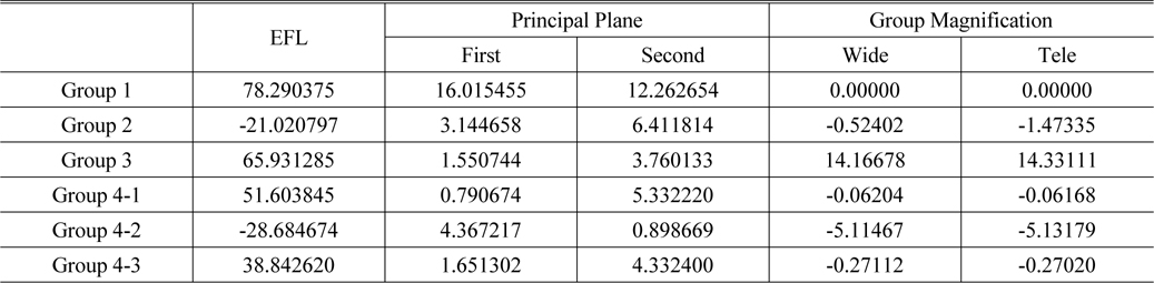
Initial first-order data, including EFL, positions of two principle planes, and group magnification of each group in the new optical system
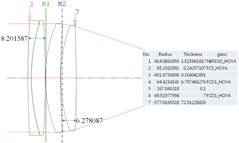
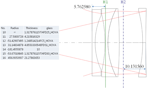
First we remove two lenses, corresponding to the sixth and ninth surfaces that previously were key when the AF group was contained in Group 1, because they are not to be used as AF lenses in the new system. As the focal lengths of the first through fifth surfaces of Group 1 are relatively long, the lens aperture become too small if it is scaled down. Therefore, we replace the sixth through ninth surfaces with a single lens and configure Group 1 using four lenses, including the existing first through fifth surfaces. To achieve this configuration, the chromatic aberrations of the sixth through ninth surfaces need to be corrected; therefore, extra-dispersion glass with a higher Abbe number is used. Furthermore, it is necessary for the new lens group with the one additional lens to have the same focal length as that of Group 1, as specified in Table 2, and for the paraxial angle of the axial ray in the ninth surface to correspond to that of Group 1 in the tele mode. Because the paraxial angle of the principal ray in the wide mode should also agree theoretically, we change the lens curvature as well. The optical layout of the new Group 1 that satisfying all of these conditions is shown in Fig. 5 below. The small table in Fig. 5 presents the lens radii, thicknesses, and glass names, the RDN data of the new Group 1.
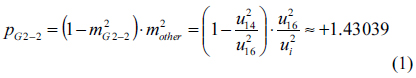
In Fig. 4, the AF group should be included in Group 2. It is easily assumed that the cemented doublet of Group 2, consisting of a concave lens and a convex lens, would have a low refractive power, based on its optical layout. A lens group with low refractive power would be limited in terms of varying its position, and hence would allow for little image plane movement, which would be inappropriate for an AF lens. Therefore, either the first or fourth lens could be chosen as the AF lens. Comparing the field curvature variations of the first and fourth lenses after shifting, however, the fourth lens exhibits less curvature change than the first lens. Thus, the fourth lens would be more suitable for use as the AF lens. If the paraxial angle of the axial ray entering the 15th surface is used as the AF lens and the paraxial angle of the axial ray exiting the 16th surface is used to find the longitudinal sensitivity [3], Eq. (1) can be readily obtained by using the paraxial lens design method.

In Eq. (1),
The same method can be used to design Group 4-2 with two lenses, and the basic configuration can be easily designed using the module-lens method [14] or the equivalent-lens method [15]. The final optical layout based on the modified Groups 1, 2, and 4-2 is shown in Fig. 7, where Figs. 7(a), 7(b), and 7(c) respectively depict the wide, normal, and tele mode layouts. However, the tele mode exhibits significant spherical aberration at this stage, because we did not consider spherical aberration when determining Group 1’s refractive power. This aberration can be corrected using the optimization function of the optical design software; thus, no significant performance correction is necessary after the basic design stage in this study.
In Fig. 7, however, it is evident that there is unnecessary interference between Groups 2 and 3, because of the wide AF space secured in Group 2. To resolve this problem, it is necessary to space Groups 2 and 3 farther apart. Also, because of the relatively large space between Groups 1 and 2 it is necessary to decrease this space, since the entire Group 2 should be able to shift toward the object. Note that if the gap between Groups 2 and 3 were still negative after shifting Group 2 toward the object, it would be necessary to space Groups 2 and 3 farther apart. As a result, the overall length of the system would not be maintained after shifting Group 2, and the overall focal length would be over-shifted, causing the field angle to be too wide. Thus, either the refractive power of each group or the spacing between each pair of groups should be readjusted. As this system consists of four groups in total, its zooming Eq. [11] can be expressed as Eq. (2) using Gaussian brackets [16]:
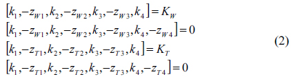
In Eq. (2),
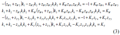
If one were to attempt to solve this equation using the gaps given in Table 2, however, the focal length of Group 4 would be too long to obtain an appropriate solution. Therefore,
[TABLE 3.] (a) RDN data and (b) zoom data of paraxial design shown in Fig. 8

(a) RDN data and (b) zoom data of paraxial design shown in Fig. 8
IV. OPTIMIZATION AND FABRICATION OF THE OPTICAL SYSTEM
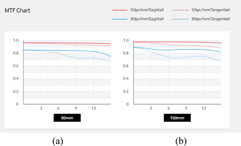
Even after completing the basic design process described in Part III, the system does not perform properly. Therefore, we use the optical design software Code V [18] to optimize the system. Because the Gaussian first-order was determined in the previous part, it is fairly simple to optimize the optical system design using this software. However, it is generally necessary to exercise caution while using this software to minimize the overall system length, and not to view productivity as excessively important when determining the system variables. Unit price also must be taken into account when assessing profitability. All of these issues can be addressed utilizing the designer’s experience and, unfortunately, no universal theory for this process exists. Figure 9 shows the optical layout of the optical system as almost fully optimized with Code V, where Figs. 9(a) and (b) present the layouts with infinite object distance and with the smallest possible object distance. From top to bottom in Figs. 9(a) and (b), the wide, normal, and tele mode layouts of this optimized telephoto zoom lens system are depicted. Figure 10 is an image of the final optical system that was fabricated after further optimization. Figure 11 shows the image resolution of the final system, indicating the modulation transfer function (MTF) values for various fields in the wide and tele modes with EFLs of 50 mm and 150 mm, respectively, where the horizontal axis represents the image height at a sensor (that is, the field angle), and the vertical axis represents the MTF value. As shown in Fig. 11, all of the MTF values are above 0.6 in both wide and tele modes, regardless of the field.
Compared to the corresponding groups in other APS-C products with similar specifications, our newly designed AF group yields the lightest weight and shortest overall length. Table 4 presents a comparison of its various specifications to those of other products released within the past five years. As shown in Table 4, the newly designed system’s AF group weighs 6 g or less at the effective lens area, representing the world’s lightest AF group among those of similar large telephoto zoom lens systems released in 2015 or earlier.
[TABLE 4.] Various design specifications of large telephoto zoom lenses
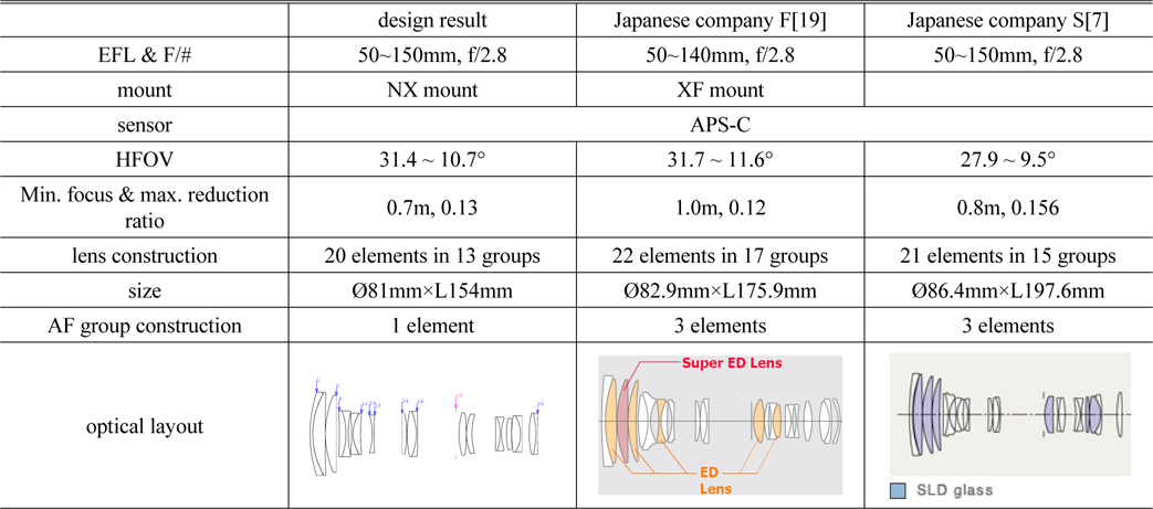
Various design specifications of large telephoto zoom lenses
Because few telephoto zoom lens systems were available in the past, it was necessary to apply the refractive power, empirically determine the number of lenses to be used in each group, and finally select the lens configuration for each group using the module-lens or equivalent-lens method to design and fabricate new, large telephoto zoom lens systems with light AF groups. However, it is now possible to utilize the vast database of patented optical systems together with a designer’s experience to achieve this objective. In this paper we have explained how to quickly obtain a new basic design by readjusting the refractive power of each group of an existing zoom lens system to satisfy selected conditions.
This paper has discussed a field-angle-based method of designing a fixed f/# telephoto zoom lens system with a light AF lens. For camera manufacturers, large telephoto zoom lenses with fixed f/2.8 would enable easy development of high-end products. To use this system in CSCs and simultaneously expedite the AF process, we used only one AF lens and, as a result, obtained a high-performance optical system with a relatively short overall length, and an additional OIS feature.


![Optical layout for wide mode of the example in KR2010-0018341 [12].](http://oak.go.kr/repository/journal/20691/E1OSAB_2015_v19n6_629_f004.jpg)