The solution process, referred to as the “sol-gel” method, has been widely studied in material engineering particularly for fabrication of complex oxide due to various process-related advantages [1-3]. Unlike the sputtering or atomic layer deposition methods, the sol-gel method does not require a vacuum process and the associated expensive equipment [4]. Moreover, complex oxide materials, in which more than two metals combine on an oxide atom, can be easily fabricated using the solgel process; the synthesis of rare earth metal and mesoporous structures such as aluminum and gallium has been studied intensively due to their structural stability, which offers advantages such as ionic diffusion limits and high deformation resistance [5-7].
Ion beam (IB) irradiation is a powerful and easy method for surface modification and has been studied widely as a representative alternative method for liquid crystal (LC) alignment [8,9]. The conventional rubbing process involves mechanical contact with a roller, resulting in debris generation, local defects, and the accumulation of electric charge, which degrades the performance of LC devices. In contrast, IB activated ions collide with the material surface, allowing for the removal of contaminations [10], thereby overcoming a weakness of the rubbing process and yielding high-quality LC devices. In addition, IB can be used with oxide materials and may be possible to expand the range of material choices for the alignment layer.
Here, we demonstrate an alternative electrically controlled birefringence liquid crystal (ECB-LC) system with an IB-irradiated yttrium gallium oxide (YGaO) alignment film using the sol-gel process. The annealing temperature was controlled to yield a high film transparency. Field-emission scanning electron microscopy (FE-SEM), atomic force microscopy (AFM), and X-ray diffraction (XRD) were used to investigate the physical properties of the surface of the YGaO films at various annealing temperatures. We also investigated the optical transmittance within a range of 250 nm ~ 850 nm at a room temperature, which is significant for display devices. To evaluate the alignment properties, polarized optical microscopy (POM) and pretilt angle measurements were investigated. Finally, the response time was measured to confirm the viability of IB-irradiated YGaO for an alternative alignment layer in ECB-LC systems.
We prepared YGaO films via the solution process. A quantity of 0.05 mol was dissolved in a solvent of 2-methoxyethanol. A few drops of acetic acid and mono-ethanolamine was added to the solution, adjusting the acidity of the solution at pH 7. The solution was stirred for 2 hr at 75℃ and aged for 1 day, then the solution was obtained in
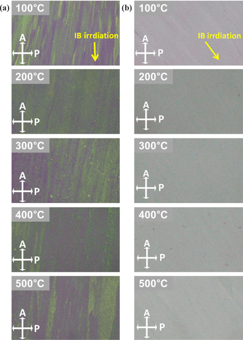
A uniform alignment state is one of the most important aspects to the LCD application. Cross-polarized optical microscopy images of LC cells, which are based on IB-irradiated YGaO at various annealing temperatures, are shown in Fig. 1. Well-aligned LCs were observed irrespective of the annealing temperature. When the well-aligned positive LCs, characterized by the planar alignment state, are placed between the intersectional polarizers, the direction of the LC alignment determines the light transmittance due to the birefringent property of LC molecules. When the positive LCs are aligned along one direction of the intersectional polarizer, the amount of light passing through the LCs is minimized, and transmittance is maximized when positive LCs are rotated 45° relative to the polarizer. As shown in Fig. 1(a), one axis of the polarizers was positioned parallel to the direction of IB irradiation (the yellow arrow has the same direction as one axis of the polarizer), resulting in a dark image. The samples were then rotated 45° relative to the polarizers [Fig. 1(b)], and white images were obtained. These results indicate that the LC molecules were homogeneously aligned on IB-irradiated YGaO films irrespective of the annealing temperature.
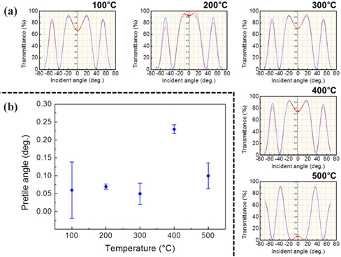
Transmittance measurements were performed under latitudinal rotation of LC samples using a crystal-rotation method to calculate the pretilt angles of the LC molecules of IB-irradiated YGaO films (Fig. 2). The blue and red curves simulated computational and experimental data, respectively, are nearly identical, indicating that the LC alignment was stable; this allowed determination of the pretilt angles with high reliability. The calculated pretilt angles of each sample at 100℃, 200℃, 300℃, 400℃, and 500℃ were 0.06°, 0.07°, 0.05°, 0.23°, and 0.10°, respectively.
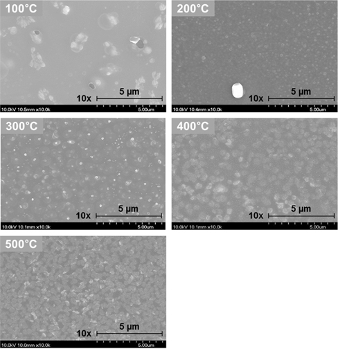
Figure 3 shows the SEM images of the surface morphology of YGaO films as a function of annealing temperature. The surface morphology of the film prepared via the sol-gel process was demonstrated to be dominantly affected by annealing temperature. FE-SEM images show that the surface morphology of the films was strongly dependent on the annealing temperature. Aggregated particles were observed on the film at the annealing temperature of 100℃. When the annealing temperature increased from 100℃ to 500℃, the aggregated particles were evenly distributed.
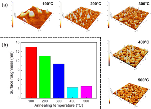
To more precisely confirm the surface state of the films, we quantified the surface roughness using AFM. Figure 4(a) shows the 3D AFM images of the surface of the YGaO films. As the annealing temperature increases, we can visually confirm the reduced height and even distribution of the sharp shapes attributable to the condensing pressure on the surface created via the sol-gel coating. At lower annealing temperatures, the coated film weakly adheres to the substrates, creates condensing pressure on the surface, and forms an uneven surface. Therefore, aggregated particles were observed at lower annealing temperatures and the surface roughness was reduced as the annealing temperature increased, the result of which is consistent with SEM images. Figure 4(b) exhibits quantitative data extracted from AFM images of the surface roughness. The calculated surface roughness of each sample at 100℃, 200℃, 300℃, 400℃, and 500℃ were 16.53 nm, 13.62 nm, 11.05 nm, 3.52 nm, and 3.92 nm, respectively. We quantitatively confirm the surface roughness of the films to be reduced at higher annealing temperatures, although the surface roughness at 400℃ and 500℃ was similar and appears to be within the experimental range (<0.5 nm). Considering the roughness of conventional rubbed polyimide (PI) ranged from 2 nm to 6 nm, the surface roughness of IB-irradiated YGaO annealed at 400℃ and 500℃ was found to be similar to PI [11,12].
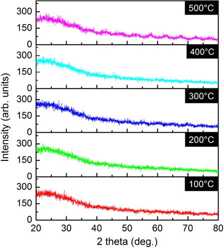
Figure 5 shows the XRD spectra of the films at various annealing temperatures. No distinguishable diffraction peaks were observed irrespective of the annealing temperature, indicating an amorphous state of the YGaO films. The crystallinity of the oxide films prepared via the sol-gel process is dependent on the annealing temperature, and a crystal structure is typically formed above 600℃ [13]. Amorphous state films occur at annealing temperatures below 500℃.
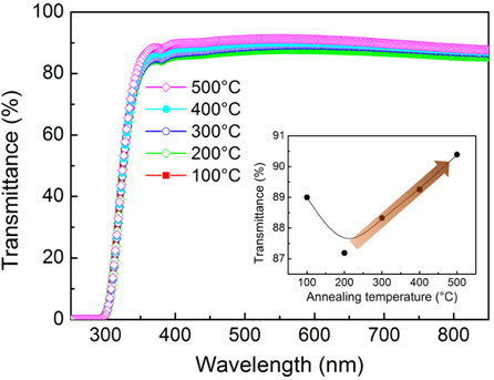
UV-Vis transmittance spectra of the films at various annealing temperatures are shown in Fig. 6. The average transmittance in the visible region ranged from 420 nm to 780 nm was over 87% for all the films regardless of the annealing temperature and the transmittance of the films showed a tendency to increase gradually as the annealing temperature increased except for 100℃ as shown in the inset of Fig. 6. Light scattering seems to occur due to the aggregated particles on the surface of the film at lower annealing temperatures. The surface roughness reduces at higher annealing temperatures and thereby increasing the transmittances of the films. Moreover, Lee et al. investigated that transmittance of rubbed PI in visible region was 83.52%, the values of which are much lower than the transmittances of IB-irradiated YGaO films [14]. Therefore, the IB-irradiated YGaO films may be strong candidates for the alignment layer of alternative LC devices.
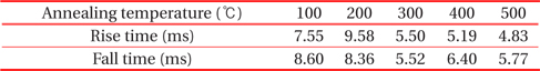
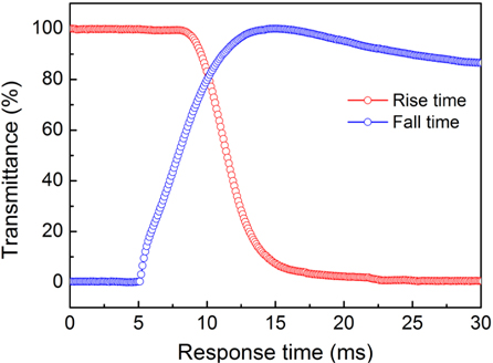
The measurement of electro-optical properties in IB-irradiated YGaO-base LC systems is the most important aspect in the realization of LC applications. The transmittance versus response time curve of ECB mode on LC cell with an IB-irradiated YGaO films at annealing temperature of 500℃ was displayed in Fig. 7, and the total response time of ECB mode on LC cell with an IB-irradiated YGaO films at different annealing temperatures was shown in Table 1. The ECB mode on LC cells at an annealing temperature of 500℃ exhibited the fastest response time of 10.6 ms (rise time of 4.83 ms and fall time of 5.77 ms) among the LC cells with various annealing temperatures, and those annealed at 200℃ exhibited the slowest response time of 17.94 ms (rise time of 9.58 ms and fall time of 8.36 ms); these values are faster than the ECB mode LC systems based on the rubbed PI reported by Jeong et al; its total response time was 19.33 ms (rise time of 6.16 ms and fall time of 13.17 ms) [15]. These results indicate that IB-irradiated YGaO-base LC systems are viable for LCD industry applications as well as showing potential for future LC applications.
[Fig. 7.] Response time of the ECB-LC systems based on the IB-irradiated YGaO film annealed at 500℃.

Response time of ECB mode on LC cell with IB-irradiated YGaO films at different annealing temperatures.
We demonstrated an alternative ECB-LC system with an IB-irradiated YGaO alignment films via a sol-gel process. The surface roughness of the films was dependent on annealing temperature. At lower annealing temperatures, aggregated particles were observed on the surface and are possibly attributed to the weak adherence between the film and the substrate. A smooth, even surface could be obtained at higher annealing temperatures and additionally, higher transmittance in the visible region was observed at higher annealing temperatures. The film was found to have an amorphous state irrespective of the annealing temperature. Furthermore, ECB-LC cell with our IB-irradiated YGaO film yielded faster response time than those of the ECB-LC cell with rubbed PI. Considering the fast response time and high transmittance, the IB-irradiated YGaO-base LC system offers a powerful alternative for the LCD industry.