Recently, mobile traffic has increased dramatically because of the proliferation of various smartphones. The CISCO Visual Networking Index [1] reported the tremens-dous growth of mobile traffic. The proliferation of global mobile traffic reached 2.5 exabytes per month at the end of 2014. Although smart devices represented 29% of the total mobile devices, they generated 69% of the total mobile traffic, and mobile video traffic made up more than 55% of the mobile traffic. Further, the ratio of traffic generated from smart devices and video traffic is expected to increase steadily.
To cope with the increased amount of mobile Internet traffic, some engineers have attempted to enhance the performance of network equipment, and the others have tried to offload the overloaded traffic to other networks. In 2014, 45% of all mobile Internet traffic was offloaded to WiFi or femtocells [1]. The other solution for the rapid increase in mobile traffic is the efficient optimization of network architectures. Such optimizations can be applied in a number of ways; one of these is the recomposition of mobility management strategies. In these aspects, the distributed mobility management (DMM) working group of the Internet Engineering Task Force (IETF) is leading considerable changes in mobility management strategies. A previous mobility management strategy called centralized mobility management (CMM) depends on centralized equipment, such as home agent (HA) and local mobility anchor (LMA). Since the home address of a mobile node (MN) is anchored at the central anchor, the MN’s packets always traverse the central anchor, leading to a path that is longer than the direct path between the MN and its corresponding node. In addition, the centralized approach has several scalability and reliability problems as central mobility anchors require sufficient processing capabilities to simultaneously deal with the traffic from all users. Moreover, the CMM strategy makes the system vulnerable to a single point of failure and makes it an easy target for attacks by a malicious adversary. In order to overcome these issues, the DMM strategy is being explored. The DMM strategy introduces a relatively flat network architecture in which mobility functions are placed closer to the users. This distributed architecture results in enhancements from the aspects of scalability and reliability; it improves the overall traffic performance of mobility management systems. Today, the content delivery network (CDN) caching servers are distributed such that each user in any location can be close to one of the servers. However, as CDN servers with the CMM strategy are applied and all traffic goes to the central anchors, the benefits of the CDN caching architecture are lost. On the other hand, the DMM strategy and the CDN architecture can work in synergy.
While a DMM strategy has several advantages, it has a relatively high signaling cost because of the tunnel establishments with many distributed anchors. As the mobility of an MN is relatively high, the portion of the signaling cost is more significant. In order to reduce the signaling cost of the DMM strategy, in this paper, we propose a novel DMM strategy combined with the pointer forwarding (PF) technique and conduct a performance analysis of the proposed strategy.
A survey of the related works is presented in Section II, and the proposed PF-DMM strategy is described in Section III. The performance of the proposed strategy is analyzed in Section IV, and the numerical results are discussed in Section V. Finally, this paper is concluded in Section VI.
The distribution architecture of mobility management functions is discussed in reports by the IETF DMM working group. Various distribution architectures based on several basic frameworks, such as mobile IPv6 (RFC5555 and RFC6275), proxy mobile IPv6 (RFC5213 and RFC5844), and NEMO BSP (RFC3963), have been proposed. Because the existing CMM strategy depends on centralized equipment, such as HA and LMA, it has several problems: suboptimal routing, scalability, reliability, and performance. The IETF DMM working group distributes the mobility functions to access routers closer to the users. Because this distribution architecture flattens the hierarchical network structure, it overcomes the disadvantages of the CMM strategy and efficiently utilizes the network resources. The various features of the CMM and DMM strategies are presented in [2,3].
Some problems with the CMM strategy that can be overcome by the DMM strategy are discussed and various mandatory and optional requirements of the DMM strategy are defined in [4]. This work considers reusing and extending IETF standardized protocols such as mobile IPv6 before specifying new protocols. In [5,6], the functional decompositions of the existing mobility management functions are described and the functional recompositions to distribute the logical mobility functions are presented.
A DMM solution with client mobile IPv6 is described in [7]. A distributed anchor router (DAR) is defined as the first access router to which the MNs attach. It also plays the role of mobility manager for the IPv6 addresses. After the MN moves to a different area of DAR, it obtains a new IPv6 address from the new access router. If the MN wants to retain the reachability of the address obtained from the previous DAR, it establishes a bi-directional tunnel with the previous DAR. Because one DAR cannot manage the security associations with too many MNs, the concept of cryptographically generated address (CGA) was proposed.
A network-based DMM solution based on proxy mobile IPv6 is proposed in [8], and its performance analysis and evaluations are presented in [9]. This study considers a partially distributed scheme where only the data plane is distributed at the edge of the network and the control plane is kept centralized.
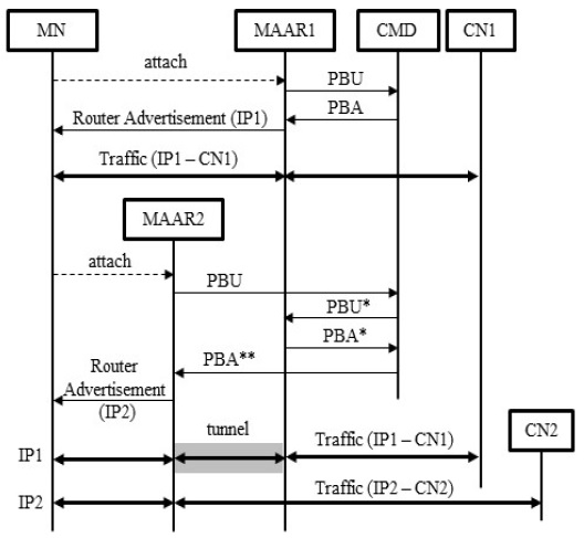
Mobility anchor and access routers (MAARs) are defined as distributed traffic anchors and access routers. They manage the global prefix pools for MNs and perform the function of handling user traffic. A central mobility database (CMD) stores the binding cache entry (BCE) allocated to the MNs and manages the global view on the network’s status. The CMD is queried whenever the MNs’ attachments are changed. Fig. 1 illustrates the basic message flow of the DMM strategy proposed in [8]. When the MN is attached to MAAR1, a new prefix (=IP1) is assigned to the MN and BCEs are created in both MAAR1 and the CMD. Typically, a BCE contains MN-ID, the MN’s prefix, and the MAAR’s address as a proxy care of address (CoA). At the first attachment of the MN, MAAR1 acts as a plain router for the MN’s packets, and no encapsulation or special handling occurs. When the MN moves to a new MAAR2, a new prefix (=IP2) is assigned to the MN and a handover procedure is initiated to serve the previous IPv6 address. When the CMD receives a proxy binding update (PBU) message from MAAR2, it detects an existing entry for the MN in an internal BCE. Thus, the CMD forwards a PBU* message including a serving MAAR option [8] to a previous MAAR1 indicated as proxy CoA. Upon PBU reception, MAAR1 forms a tunnel with MAAR2 and replies with a modified proxy binding acknowledgment (PBA*) message including the previous MAAR option. After receiving a PBA* message from MAAR1, the CMD updates the BCE information for the MN. If there are multiple previous MAARs, the CMD awaits the PBA* messages from all previous MAARs. In order to perform this waiting procedure, a previous MAAR list per MN is also included in a BCE. Each element of this MAAR list contains the previous MAAR’s address and the IPv6 address assigned to the MN. Furthermore, the CMD sends a PBA** message including the previous MAAR list [8] to the new serving MAAR2. Upon receiving a PBA** message, a bi-directional tunnel is established between the two MAARs. Finally, packets destined for the prefix IP1 are received by MAAR1, encapsulated into the tunnel, and forwarded to MAAR2, which delivers them to their destination. Packets using the prefix IP2 are routed to MAAR2 without any tunneling. After further handover events to another MAAR, both MAAR1 and MAAR2 can be included in the previous MAAR list as mobility anchors.
In this paper, we chose a partially distributed strategy based on proxy mobile IPv6, as in [8]. Therefore, while the data processing functions are distributed at the MAAR, the signaling processing functions are centralized at the CMD. The CMD deals with the signaling messages for mobility management, manages the mobility database of all MNs, and is involved in the tunnel establishments between one serving MAAR and several anchoring MAARs. In the distribution of the mobility management functions, as the MN moves faster, the number of anchoring MAARs increases. Because the number of tunnels between the anchoring MAARs and the serving MAAR is proportional to the increased number of anchoring MAARs, the DMM strategy incurs a significant signaling cost. To overcome this drawback, we propose the PF-DMM strategy, which applies a PF technique with a DMM strategy. The PF technique adds a new tunnel between an old serving MAAR and a new serving MAAR at the handover of the MN. As it keeps the tunnels of the anchoring MAARs and extends the traffic path, it can reduce the expense of the location update. The concept of PF is based on the mobility management schemes for cellular networks [10]. With a PF technique, a handover event involves setting up a forwarding tunnel between two neighboring MAARs without having to trigger a location update event.
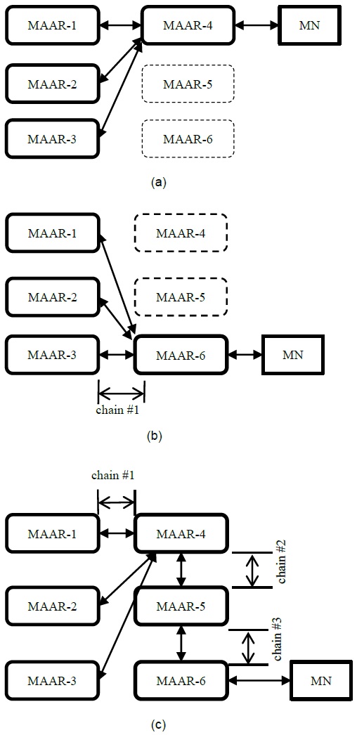
Fig. 2 presents the handover operations of the typical DMM and PF-DMM strategies. We assume that the MN is attached to MAAR-1 and moves to MAAR-2, MAAR-3, MAAR-4, MAAR-5, and MAAR-6 consecutively. Then, new IP addresses are assigned by MAAR-1, MAAR-2, and MAAR-3. However, we assume that no IP addresses are assigned by MAAR-4, MAAR-5, and MAAR-6, because of the limited maximum number of IP addresses. Fig. 2(a) shows that the MN is connected to a serving MAAR, e.g., MAAR-4, and three MAARs, namely MAAR-1, MAAR-2, and MAAR-3, operate as the anchoring MAARs. As the MN moves to other MAARs, the serving MAAR is changed and the tunnels are re-established with the three anchoring MAARs in the typical DMM strategy, as shown in Fig. 2(b). Therefore, there is only one tunnel, which is called a chain, in the packet delivery path of a typical DMM strategy. However, because the delivery path is extended in the PF-DMM strategy, the number of chains is increased, as shown in Fig. 2(c). When MAAR-1 receives the user packets destined for the MN, it encapsulates the packets and tunnels them to the next MAAR (e.g., MAAR-4). After MAAR-4 decapsulates the tunneled packets, it encapsulates the decapsulated packets and again tunnels them to MAAR-5. MAAR-5 performs the same operation, and MAAR-6 finally delivers the user packets to the MN. In short, because the PF-DMM strategy extends the traffic path with additional tunnels, it results in an inefficient routing path. Therefore, the proposed PF-DMM strategy shows outstanding performance in the signaling plane but exhibits poor performance in the data plane.
As shown in Fig. 2, because the PF-DMM extends the routing path with additional tunnels, the number of chains is greater than 1.
That is, as the number of chains is increased, the traffic path is extended and the traffic performance is degraded. Therefore, to avoid excessive path extension, we propose that the PF-DMM strategy restrict the number of chains. The CMD can monitor the number of chains for the MN and determine whether to extend with a new chain or not. As soon as the number of chains exceeds the threshold value, the CMD establishes a new tunnel between the anchoring MAARs and a new serving MAAR, and removes the old existing tunnels. We call this the path reconfiguration (PR) procedure. Using the PR procedure, the PF-DMM can restrict the excessive extension of chains and prevent the degradation of the traffic performance in the PF-DMM strategy. In summary, the PF-DMM strategy combines the PF and PR operations.
Because the portion of the signaling cost in the protocol cost is large in the case of high mobility, the PF technique can result in a considerable performance improvement. In contrast, in the case of low mobility, the packet delivery efficiency is more significant than the signaling cost, and the PR technique is a more appropriate method than the PF technique. Furthermore, the number of chains for specific users can be configured for each user as discussed in [11,12]. Because the CMD manages the mobility information and controls the related parameters, it can adjust the maximum number of chains per MN. When the MN is handed over to another cell, it can determine whether to use the PF technique or the PR technique. All MAARs should follow directions from the CMD and are unaware of which technique is used. Thus, a MAAR’s operations are not related to the mobility strategy, and the implementation of the CMD is affected by the PF-DMM strategy.
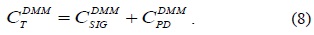
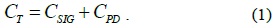
In this section, in order to analyze the performance of the proposed PF-DMM strategy, we use the protocol cost as the performance metric, as in [13]. The total protocol cost is the sum of the signaling cost and the packet delivery cost, as shown in Eq. (1).
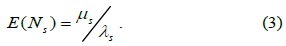
The signaling cost,
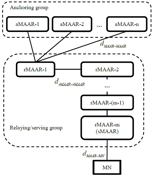
To analyze the performance of the PF-DMM strategy, we assume a network topology shown in Fig. 3. In this topology,
We make additional assumptions for the mobility and traffic models. The session arrival process follows the Poisson distribution with a rate
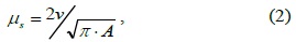
where
>
B. Performance Analysis of the Typical DMM Strategy
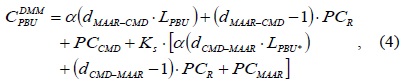
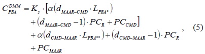
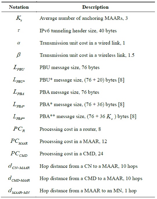
In Table 1, we define several notations and default values for analyzing the typical DMM strategy. The performance analysis of a typical DMM strategy was presented in [9] using the notations listed in Table 1. In order to determine the signaling cost, we should consider the PBU and PBA messages. The signaling cost for transmitting a PBU message is calculated using Eq. (4). After the CMD receives a PBU message that the new serving MAAR sends, it forwards the PBU* message to the anchoring MAARs with a serving MAAR option [13]. Thus, the message forwarding path from a serving MAAR to the anchoring MAARs via CMD is included in Eq. (4). The signaling cost for transmitting a PBA message is calculated in Eq. (5). Then, the anchoring MAARs reply with a PBA* message to the CMD. After the CMD receives multiple PBA* messages from the multiple anchoring MAARs, it aggregates them into one PBA** message and forwards it to the serving MAAR. The total signaling cost is calculated using Eq. (6).


[Table 1.] Notations for the typical DMM strategy.

Notations for the typical DMM strategy.
Let

Further, using the signaling cost and the packet delivery cost, we obtain the total cost of the typical DMM strategy as follows:

>
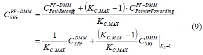
C. Performance Analysis of the PF-DMM Strategy
We define additional notations and default values for analyzing the PF-DMM strategy in Table 2. It is assumed that the maximum number of chains is three. However, because the optimal maximum number of chains varies with the circumstance, we will try to determine the optimal value in the next section. Moreover, for the time being, we assume that the distance between the MAARs is approximately the square root of the distance between the CMD and the MAAR.
[Table 2.] Additional notations for the PF-DMM strategy

Additional notations for the PF-DMM strategy
As previously mentioned, the PF-DMM strategy’s operation is the combination of the PF and PR operation. If the maximum number of chains is described by
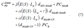
Upon considering the packet delivery path from the MN to the CN, there is a huge overlapping path between the typical DMM and the PF-DMM strategies. Except for the portion on the path between the relaying MAARs, the remaining delivery path is the same. Because the PF-DMM strategy has an additional delivery path between the relaying MAARs, it incurs a higher packet delivery cost than the typical DMM. Considering the additional paths, we can calculate the average packet delivery cost as follows:
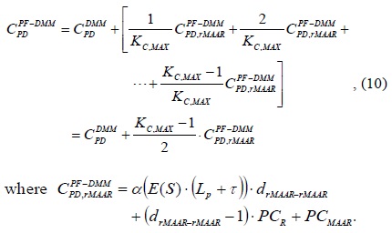
The additional cost, denotes the packet delivery cost via a tunnel between the relaying MAARs established by the PF technique. When the value of

In this section, we present and compare the performance results of the typical DMM and the PF-DMM strategy. For any numerical result in which specific system parameters are not provided, the following parameters are used:
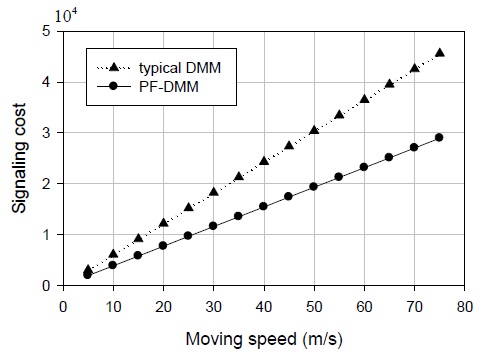
Fig. 4 shows that the signaling cost tends to increase with an increase in the moving speed. When the moving speed is low, it is difficult to verify the advantages of the PF-DMM strategy. However, in case of high speed, the PF-DMM strategy outperforms the typical DMM strategy. As the speed increases, the binding update events are more frequent. While the typical DMM strategy deals with the PR operation at all the handover events, the PF-DMM extends the packet delivery path by the PF technique at the same time. Because the PR operation is heavier than the PF operation, the typical DMM strategy incurs a higher signaling cost than the PF-DMM strategy. Therefore, in cases of frequent handover events, the PF-DMM strategy outperforms the typical DMM strategy.
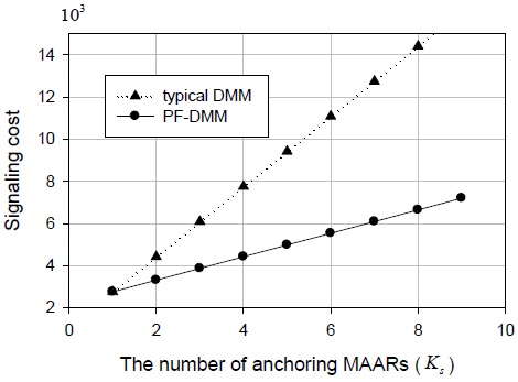
Fig. 5 presents the signaling cost versus the number of anchoring MAARs. In general, with an increase in the number of anchoring MAARs, the signaling cost increases. On the other hand, Fig. 5 shows that the PF-DMM strategy seems less sensitive to a change in the number of anchoring MAARs than the typical DMM. The number of anchoring MAARs represents the number of tunnels to be established in a PR operation. While the typical DMM strategy deals with the PR operation at all handover events, the PF-DMM strategy carries out multiple PF operations and one PR operation. Therefore, the PF-DMM strategy incurs a lower signaling cost than the typical DMM strategy. In particular, with an increase in the number of anchoring MAARs, the performance difference becomes more remarkable.
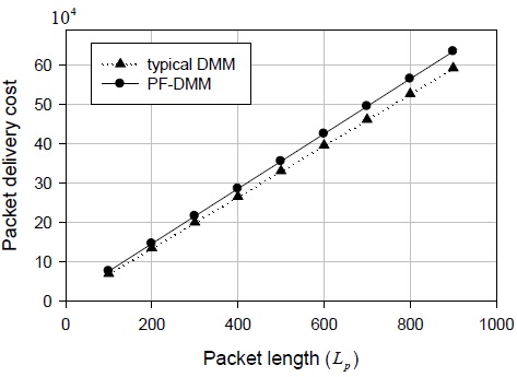
The relationship between the packet delivery cost and the packet length is shown in Fig. 6. With an increase in the packet length, the packet delivery costs of both the typical DMM and PF-DMM strategies increase. As described in Section IV, the PF-DMM strategy exhibits poor performance from the viewpoint of the packet delivery cost.
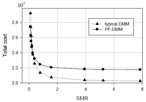
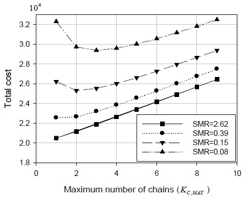
Fig. 7 shows the total cost versus the session to mobility ratio (SMR). Two aspects are illustrated in Fig. 7. A low SMR (=
The high SMR value indicates that the handover events are rare and the packet delivery events are frequent. Therefore, when the SMR value is high, the drawback of the PF-DMM strategy is emphasized.
As already mentioned, the proposed PF-DMM strategy has pros and cons. In short, the optimal maximum number of chains,
Although the typical DMM strategy exhibits outstanding traffic delivery performance, it has a higher signaling cost because of the tunnel establishments with many distributed anchors. As the mobility of MN is higher, the portion of the signaling cost in the total protocol cost is more significant and the disadvantage of the DMM strategy is increasingly exposed. In this study, in order to reduce the excessive signaling cost of the typical DMM strategy, we applied the PF technique to the DMM strategy and devised the PF-DMM strategy. Using the PF technique, we maintained the existing tunnels and established a new additional tunnel. Because it retained the existing packet delivery path, we could reduce the signaling cost for the path reconfiguration, but the packet delivery cost increased because of the extended path. The proposed PF-DMM strategy exhibited outstanding performance in the case with high mobility and low session arrival rate. In the worst case, it showed the same performance as the typical DMM strategy by reducing the maximum number of chains. The CMD managed the status of every MN and updated the database per MN. Therefore, it could calculate the optimal maximum number of chains per MN and determine whether to use PF or perform path reconfiguration at the handover event. Moreover, it optimized the operation of the PF-DMM strategy per MN. In the future, we intend to develop a DMM strategy with flow mobility and network mobility.