The allocation of the frequency band from 3.1 to 10.3 GHz by the Federal Communication Commission (FCC) for ultra-wideband (UWB) radio applications has presented an opportunity and a challenge for antenna designers to develop antennas that operate in this very wide frequency band. The FCC first approved rules for the commercial use of UWB in February 2002. By April of that year, the FCC gave formal approval for the unlicensed use of technology in the UWB range [1].
Since then, the feasible design and implementation of UWB systems has become a highly competitive topic for research and development in academia and the telecommunications industry. The antenna forms a critical component of UWB systems and hence has attracted significant research interest in the past few years [2]. Challenges involved with the development of a feasible UWB antenna design for consumer electronics applications include impedance matching and radiation stability over the entire UWB, as well as a compact size and low manufacturing cost.
Slot antennas have advantages over other planar antennas of wider bandwidth, superior impedance matching, lower dispersion, and lower radiation loss. They also have a low cost of construction using conventional printed circuit board (PCB) technology and the possibility of obtaining a bidirectional radiation pattern. Therefore, the slot antenna is one of the most promising candidates for UWB applications and an upsurge has occurred in research on the slot antenna for UWB applications [3,4].
The characteristics of printed wide-slot antennas fed by a microstrip line with a simple tuning stub have been of particular interest [5-12]. These antennas have an advantage of wide operating bandwidth, especially when modifying tuning stubs, such as a U-shaped tuning stub or fork-like tuning stub.
In this article, we report a new modified circular slot antenna design with a fork-like tuning stub for UWB operation, and investigate its radiation characteristics. The fork-like tuning stub studied herein is positioned within the slot region at the opposite side of the printed modified circular slot. Proper selection of the simulation parameters of the fork-like tuning stub predicts that the coupling between the fork-like tuning stub and printed modified circular slot will be more effectively controlled, making wideband operation possible with this proposed modified circular slot antenna.
The antenna was fabricated from conventional FR-4 material, which is often used in making printed circuit boards and is therefore easy to manufacture. Experimental results on antenna broadband impedance bandwidth, radiation pattern, and gain are discussed in detail in the subsequent sections.
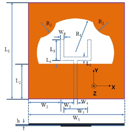
Fig. 1 shows a schematic of the proposed antenna design configured with the modified circular slot antenna fed by fork-like tuning stub. The proposed antenna is printed on a FR4 substrate with thickness of 1.0 mm, relative permittivity of 4.4, and loss tangent 0.02. The total sizes of the substrate and the ground plane of the proposed antenna were 30.0 mm × 34.0 mm (W1 × L1) and 30.0 mm × 12.5 mm (W1 × L2), respectively. The proposed antenna consists of a square substrate into which a circular slot is etched at the center of the ground plane. Two grounded semicircular metallic strips are placed in the upper corners of the circular slot, which is a modified ground plane, to achieve a broadband bandwidth. The proposed antenna is fed by a fork-like tuning stub.
The modified circular slot is fed by a 50-microstrip line with a fork-like tuning stub, which is printed on the opposite side of the microwave substrate and placed symmetrically with respect to the centerline of the modified circular slot. The circular metallic strip at the upper corner of the circular slot has a radius R2 = 3.6 mm. The inner circular slot radius R1 is 13.5 mm. The fork-like tuning stub is composed of a straight section of length W4 and two branch sections of equal lengths L3; the spacing between the edges of the two branch sections is W5. These sections have the same widths and are equal to W4 of the 50-microstrip line. The bandwidth of the antenna was optimized by varying the following dimensions in steps, and calculating the antenna’s bandwidth for each step: the radius (R1) of the inner circular slot, the radius (R2) of the circular metallic strip, the length (L3) of the two branch sections in the fork-like tuning stub, the gap (W5) between the two branch sections of the fork-like tuning stub, and the small gap (L4) between the fork-like tuning stub and slot region in the opposite side of the printed modified circular slot were made to vary in steps.
The design of the proposed antenna concurs with the described guidelines followed for the optimization with the commercially available software Ansoft High Frequency Structure Simulator (HFSS) version 10.0 (ANSYS Inc., Canonsburg, PA, USA), a full-wave commercial EM software capable of simulating a finite substrate and a finite ground structure. Parametric studies were conducted to investigate the wideband characteristics of the proposed antenna. A parametric study is important for a new design because it enables the antenna designer to understand antenna characteristics. Therefore, the effects of design parameters for the modified circular slot and fork-like tuning stub were investigated for the antenna characteristics.
>
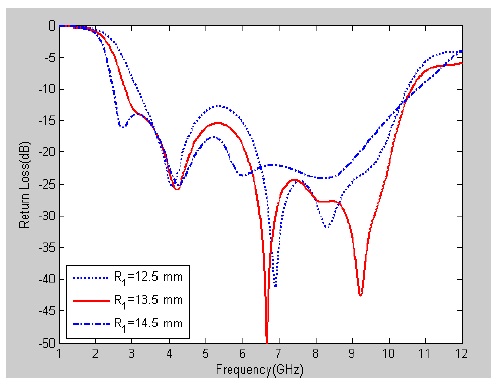
A. Effect of the Radius of Circular Slot (R1)
Fig. 2 shows the simulated return loss curves when the radius of the inner circular slot is varied (R1 = 12.5, 13.5, and 14.5 mm) and other parameters remain unchanged as optimal. The return loss curves vary substantially. When R1 is 12.5 mm, the simulated lower band of the return loss performance (3.186–10.50 GHz) deviates from the required UWB bandwidth (3.1–10.3 GHz). When R1 is 14.5 mm, the simulated return loss performance is reduced, resulting in poor UWB bandwidth. The optimal radius of the inner circular slot is 13.5 mm.
>
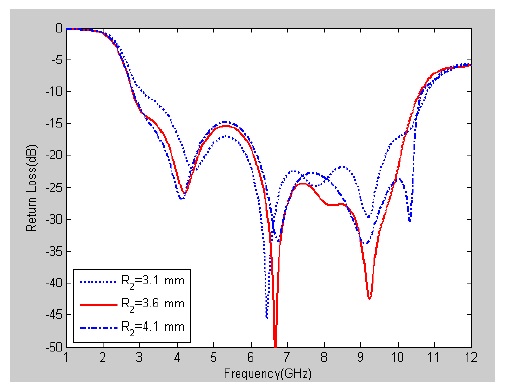
B. Effect of the Radius of Circular Slot (R2)
Fig. 3 shows the simulated return loss curves when the radius of the outer circular slot is varied (R2 = 3.1, 3.6, and 4.1 mm) and the other parameters remain at optimal values. The return loss curve in this case is not greatly changed. When R2 is either too large or too small, in the cases of R2 = 3.1 mm and R2 = 4.1 mm, the impedance bandwidth within the UWB band or the characteristics of return loss are similar. However, when R2 is 3.6 mm, the characteristics of return loss within the UWB band are better than those of return loss. Therefore, the optimal radius of the outer circular slot is 3.6 mm.
>
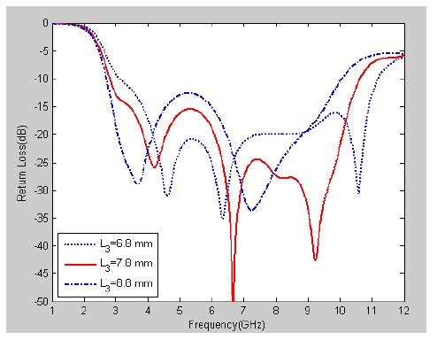
C. Effect of the Fork-like Feed Length (L3)
Fig. 4 shows the simulated return loss curves with different values of the fork-like feed length (L3 = 6.8, 7.8, and 8.8 mm) when other parameters remain at optimal values. The return loss curves vary substantially. For instance, when L3 is 6.8 mm, the simulated lower band of the return loss performance (3.1–10.3 GHz) deviates from the required UWB bandwidth. When L3 is 8.8 mm, the simulated return loss performance is poor in the mid-band and the simulated higher band of the return loss performance (3.1–10.3 GHz) deviates from the required UWB bandwidth. The optimal fork-like feed length is 7.8 mm.
>
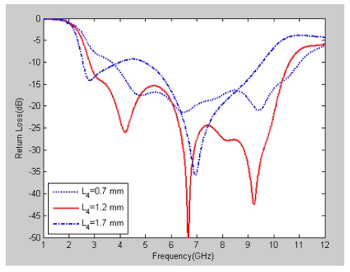
D. Effect of the Gap Width between the Fork-like Feed Line and the Ground Plane (L4)
Fig. 5 shows the simulated return loss curves with different values of the gap width between the fork-like feed and the ground plane (L4 = 0.7, 1.2, and 1.7 mm) when other parameters remain at optimal values. The return loss curves vary significantly with the variation of L4. When L4 is either too large or too small, that is, in the case where L4 = 0.7 mm and L4 = 1.7 mm, the impedance bandwidth within the UWB band is deviated to a lower band or a higher band, respectively. The optimal gap width between the fork-like feed and the ground plane is 1.2 mm.
>
E. Effect of the Gap Width between the Fork-like Feed (W5)
Fig. 6 shows the simulated return loss curves with different values of the fork-like feed width (W5 = 11.15, 12.15, and 13.15 mm) when other parameters remain at optimal values. The return loss curves vary substantially. When W5 is 11.15 mm, the simulated return loss performance is poor in the mid-band. When W5 is 13.15 mm, the simulated higher band of return loss characteristics (3.1– 10.3 GHz) deviates from the required UWB bandwidth. The optimal fork-like feed length is 12.15 mm.
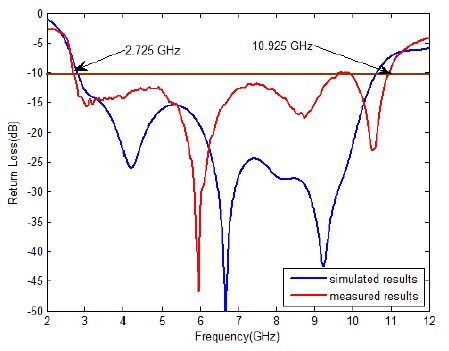
The values of the design parameters shown in Fig. 1 were calculated using the optimized Ansoft HFSS. Thus, the dimensions of the proposed antenna were set as follows: R1 = 13.5 mm; R2 = 3.6 mm; L1 = 34.0 mm; L2 = 12.5 mm; L3 = 7.8 mm; L4 = 1.2 mm; L5 = 1.0 mm; W1 = 30.0 mm; W2 = 8.8 mm; W3 = 5.325 mm; W4 = 1.5 mm; W5 = 12.15 mm; W6 = 1.0 mm; and h = 1.0 mm. The simulation results generated a -10 dB bandwidth at 7.982 GHz (from 2.743 to 10.725 GHz).
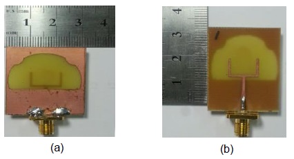
The proposed antenna was constructed and measured for the UWB operating band. Fig. 7 shows a photograph of the fabricated antenna. Fig. 7(a) and (b) show the front and back view of the fabricated antenna, respectively. The measured results are obtained using the Anritsu MS4644A vector network analyzer. Fig. 8 describes the simulated and measured
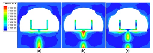
A better understanding of the excitation behavior of the proposed antenna was sought by studying the surface current density excitation along the three branch strips for the three resonant frequencies of 4.19, 6.67, and 9.23 GHz, as displayed in Fig. 9(a)–(c), respectively. The first resonant mode (Fig. 9(a)) shows the current distribution is mainly focused at the bottom of the fork-like tuning stub, whereas the second mode (Fig. 9(b)) shows the current distribution becoming more concentrated along the end of the fork-like tuning stub. The third resonant mode (Fig. 9(c)) shows the current distribution becoming more concentrated along the end of the fork-like tuning stub and at the bottom of the fork-like tuning stub. In each of these resonant modes, a large surface current density is concentrated along the microstrip feed line.
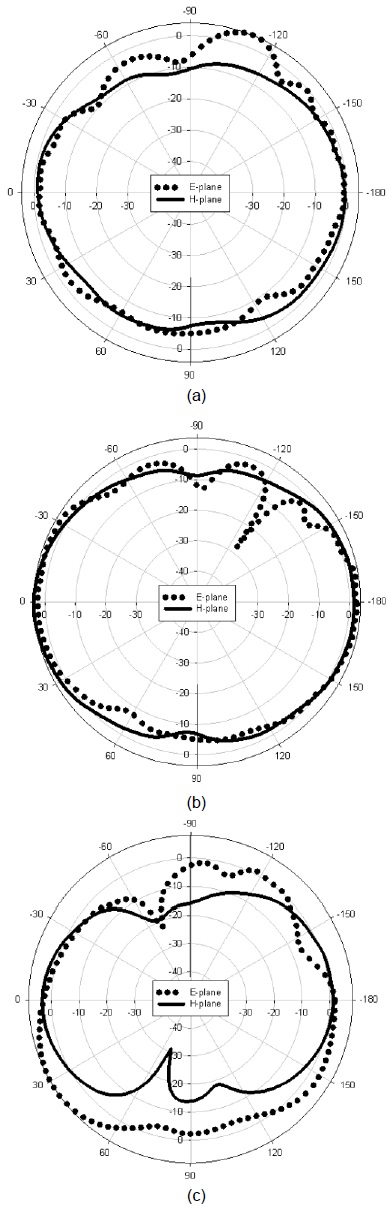
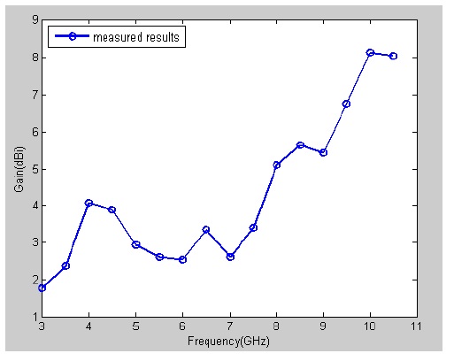
Fig. 10 shows the measured 2D far-field radiation patterns in the E-plane (x-z plane) and H plane (y-z plane). Fig. 10(a)–(c) show the 2D radiation patterns at 4, 7, and 10 GHz, respectively. These radiation patterns indicated that the proposed antenna displayed nearly omnidirectional radiation characteristics in the H-plane and monopole-like radiation pattern characteristics in the E-plane at the frequencies considered. Fig. 11 shows the 2D measured antenna peak gain for the frequencies across the UWB bands. The UWB band had an antenna peak gain level of about 2.539–8.152 dBi.
A modified circular slot antenna fed by a fork-like tuning stub was proposed for UWB applications. The optimum parameters were produced by varying the radius of the inner circular slot, the radius of the circular metallic strip, the length of the two branch sections in the fork-like tuning stub, the gap between the two branch sections of the fork-like tuning stub, and the small gap within the fork-like tuning stub. The results of studies on surface current distributions of the operating frequency bands were discussed. A modified circular slot and fork-like tuning stub were fabricated on the substrate to achieve UWB frequency bands. The proposed antenna had an impedance bandwidth (return loss: -10 dB definition) of about 8.2 GHz (2.725–10.925 GHz). This monopole antenna exhibits a nearly omnidirectional radiation pattern in the H plane and a dipole-like radiation pattern in the E-plane. An antenna gain range from 2.539 to 8.152 dBi is achieved. The antenna presented is appropriate for UWB system applications.