Recently, ultrawideband (UWB) communication systems have received increasing attention for automotive, medical, and radar applications because they support a high data rate, low power consumption, and are low cost [1-5]. Because UWB communication systems are integrated into a variety of electronic devices, the available area for a universal UWB antenna is limited [6]. The UWB antenna should not only have a compact size, a low profile, and a low cost, but should also have a stable and omnidirectional radiation pattern [7-9]. Also, the Federal Communications Commission (FCC) requires that UWB antennas operate in the frequency range from 3.1 GHz to 10.6 GHz [10].
The planar inverted-F antenna (PIFA) with a resonant length of
To overcome this problem, a low-profile PIFA with a slotted ground plane for UWB applications is proposed. This antenna has a bandwidth covering the full UWB frequency range (3.1 GHz to 10.6 GHz), with improved impedance matching by utilizing the additional resonance of the slot on the ground plane. The antenna has a stable and nearly omnidirectional radiation pattern over the full UWB frequency range.
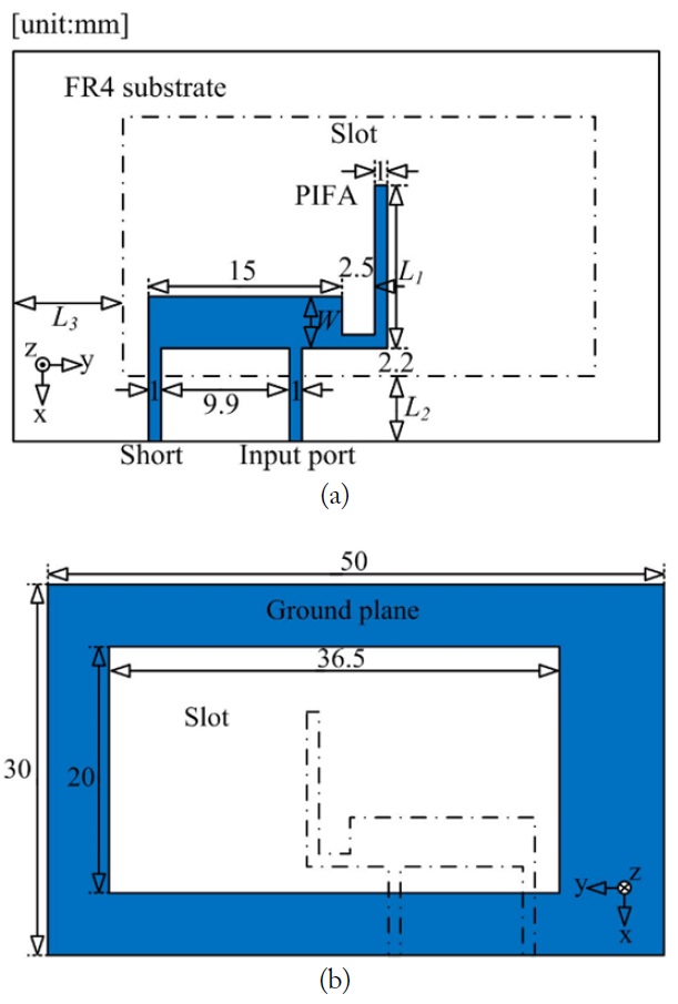
Fig. 1 shows the geometry of the proposed antenna. The proposed antenna consists of a PIFA element and a ground plane with a slot. The PIFA is placed on the top of an FR4 substrate (
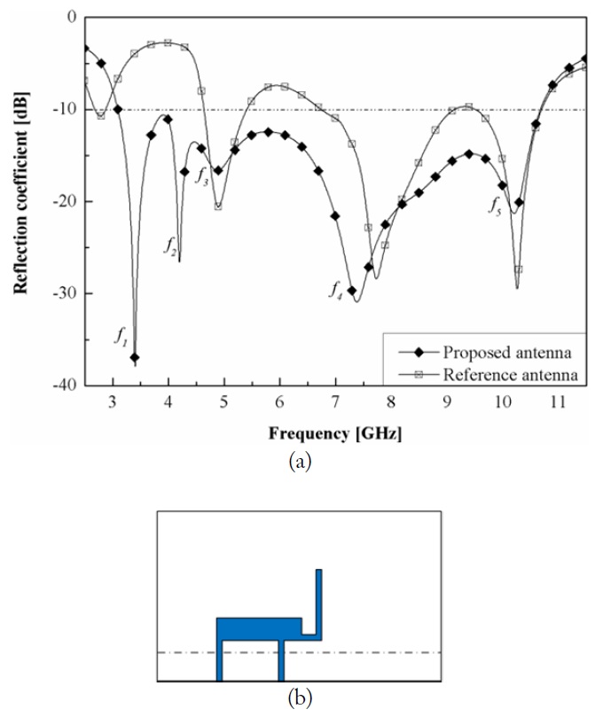
To investigate the effect of the slot, reflection coefficients of the proposed antenna and the reference antenna are compared in Fig. 2. The reference antenna has a basic PIFA structure that is the same as the proposed antenna, except without a slot. By adding the slot in the ground plane, the impedance matching of the PIFA is improved and the additional resonance
III. SIMULATED RESULTS AND ANALYSIS
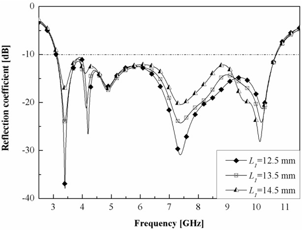
Fig. 3 illustrates simulated reflection coefficients for various values of
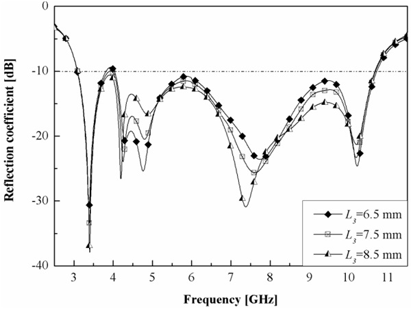
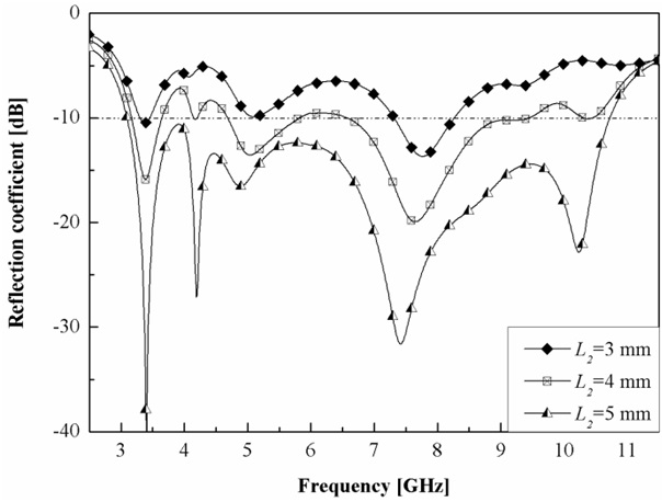
In Fig. 4, simulated reflection coefficients for various values of
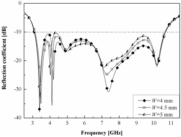
Fig. 5 shows simulated reflection coefficients for various values of
In Fig. 6, simulated reflection coefficients for various values of
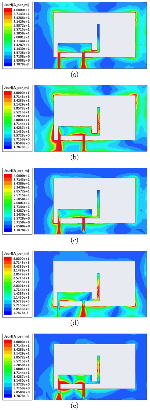
Fig. 7 illustrates the simulated surface current distributions of the proposed antenna, illustrating the coupling between the PIFA and the ground plane. The current distributions in Fig. 7(a), (c), (d), and (e) show that the PIFA has an effective electrical length of
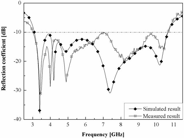
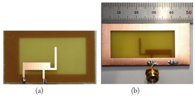
A prototype of the proposed antenna is shown in Fig. 8, and simulated and measured reflection coefficients are compared in Fig. 9. The measured result is virtually identical to the simulated result. The measured -10 dB reflection coefficient bandwidth (3 GHz to 10.65 GHz) covers the full UWB frequency range.
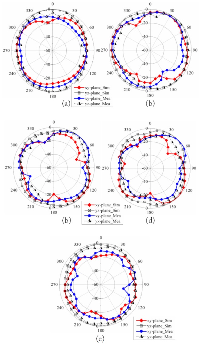
Fig. 10 shows simulated and measured radiation patterns of the proposed antenna. The measured results agree with the simulated results and show a stable and nearly omnidirectional radiation pattern. The measured peak gains of the antenna are 4.94 dBi at 3.4 GHz, 3.8 dBi at 4.19 GHz, 3.31 dBi at 4.88 GHz, 2.78 dBi at 7.39 GHz, and 5.38 dBi at 10.2 GHz.
Volume, thickness, and bandwidth comparisons between previous UWB PIFAs and the proposed antenna are given in Table 1. Previous UWB PIFAs also are either not satisfying the full UWB frequency range despite their larger volume [13-15] or satisfying the full UWB frequency range with larger volume [16]. As shown in Table 1, the proposed antenna has the smallest volume and thickness. The overall volume and thickness of the proposed antenna is minimized because wideband impedance matching is obtained by electromagnetic coupling between the PIFA and the thin ground plane.
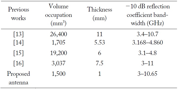
Volume, thickness, and bandwidth comparisons between previous UWB PIFAs and the proposed antenna
A low-profile PIFA with a slot for UWB applications is proposed in this paper. The addition of a slot on the ground plane improves the impedance matching of the PIFA and adds an additional resonance due to coupling between the PIFA and the ground plane. Consequently, the antenna has a wide -10 dB reflection coefficient bandwidth of 7.65 GHz covering the full UWB frequency range (3.1 GHz to 10.6 GHz). The antenna also provides a stable and nearly omnidirectional radiation pattern over the full UWB frequency range. These advantages make the proposed antenna a promising candidate for UWB applications.