Recently, power amplifiers (PAs) have been studied extensively for better efficiency and bandwidth, as communication devices need to support various technologies and exhibit a longer battery time. In an effort to address the issue of efficiency, architectures that exploit harmonic waveforms, such as class-F, have been widely studied from many perspectives [1,2]. Although the theoretical efficiency of class-F amplifiers approaches 100% and their implementation results are very close to the ideal values, the circuit implementations of class-F amplifiers are necessarily bulky in general, because they require high-order harmonic control circuits, even though some techniques have been suggested to overcome these practical issues [3–6]. Furthermore, the need to control harmonic impedances necessarily results in a relatively narrow bandwidth. For these reasons, class-F amplifiers have not been used for the latest commercial applications that require a wide bandwidth. Therefore, this paper suggests a power amplifier design with split transmission lines to realize wide bandwidth while maintaining a small circuit area. In addition, in order to further improve the performance obtained in the previous work [7], this paper redesigned the slant-end architecture using split slant-end transmission lines and impedance optimization.
II. STEPPED TRANSMISSION LINE FOR BROADBAND OPERATION
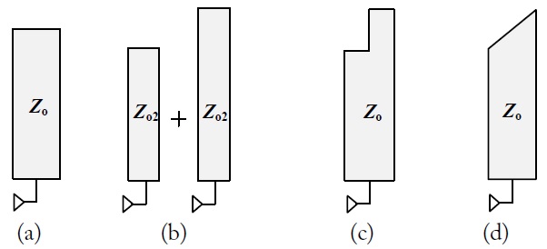
Fig. 1 shows the steps for broadening the bandwidth of transmission lines in matching networks. In transmission lines, physical parameters such as length, width, height, and the dielectric constant all influence the electrical length at a certain frequency. As such, the conventional transmission line in Fig. 1(a) results in a narrow bandwidth. In other words, amplifiers that rely on transmission lines for harmonic matching networks necessarily show limited operational bandwidth.
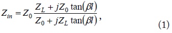
The input impedance of a transmission line is approximated as follows [8]:

where
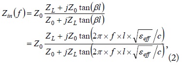
This impedance can be expressed as a function of frequency,

where
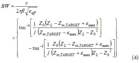
Assuming that the efficiency is mainly affected by the output impedance, the bandwidth of the transmission lines can be found from
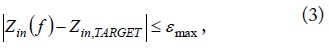
where
In the case of a conventional transmission line, particularly, the bandwidth can be analytically found from (2) and (3):

When two transmission lines of different lengths are connected in shunt, as shown in Fig. 1(b), the combined line will have a “stepped” shape at the end (Fig. 1(c)), resulting in a combined impedance as follows:
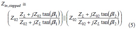
where
Therefore, the transmission line in Fig. 1(c), combining the shapes of Fig. 1(b), would have near zero ohms at the frequencies at which the shortest and the longest parts of the line each becomes one quarter wavelength. This effectively results in a wider bandwidth as an impedance inverter.
Furthermore, a transmission line with a slant end, as shown in Fig. 1(d), could be regarded as having shunt connections of an infinite number of narrow stepped-end lines with incremental lengths, so it shows a better frequency response. Its impedance is expressed with (6), as follows:
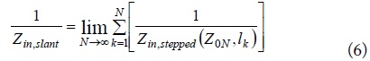
Table 1 compares the estimated bandwidth of transmitssion lines of Fig. 1(a), (c), and (d) at 3.4 GHz, at which the transmission lines are designed as second-harmonic shorts. In Table 1, the stepped- and the slant-end line shows wider bandwidth than the conventional one when an impedance under 5 Ω is regarded as the target impedance.
[Table 1.] Bandwidth comparison between conventional, stepped-end, and slant-end impedance inverters
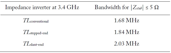
Bandwidth comparison between conventional, stepped-end, and slant-end impedance inverters
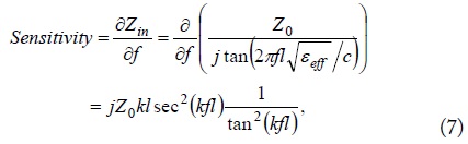
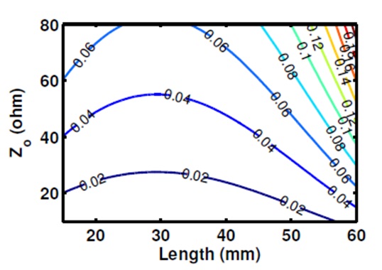
In addition, in order to further improve the bandwidth over the characteristic impedance of the abovementioned open stubs, the sensitivity of the impedance

where
This equation is used to find the optimal length and the characteristic impedance of the open-end stub to achieve the widest bandwidth in harmonic idlers (Fig. 2), at which 20–30 Ω show the lowest
III. DESIGN AND MEASUREMENT OF BROADBAND CLASS-F AMPLIFIER
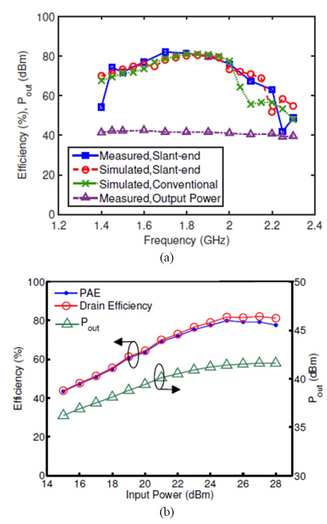
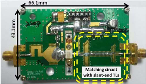
To verify the proposed design, a class-F PA operating at 1.7 GHz was designed by employing a commercial 10 Watt, GaN HEMT transistor and was implemented on an FR4 substrate. The drain bias voltage was set to 28 V, and the bias current was set to 200 mA.
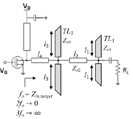
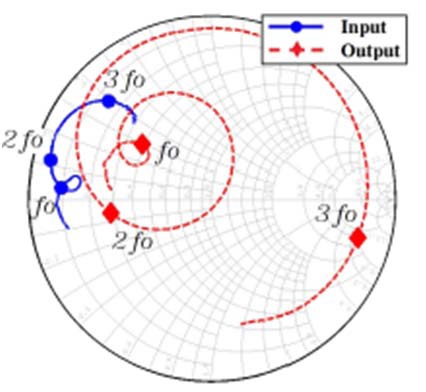
Using the aforementioned equations, a wideband matching network for a class-F PA was designed (Fig. 3). From the load-pull simulation based on the transistor model provided by the manufacturer, the fundamental impedance was set as 17+
[Table 2.] Performance comparison between wideband power amplifiers
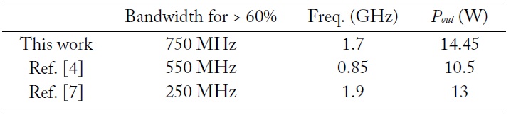
Performance comparison between wideband power amplifiers
This paper presents a design method to achieve wide bandwidth and high efficiency for power amplifiers. By splitting open-end transmission lines in the output matching network, the conditions for class-F operation could be maintained over a wider bandwidth. Furthermore, the circuit occupies less area than conventional wide-band class-F designs that require many harmonic controllers. To verify the suggested design, a broadband class-F PA operating at 1.7 GHz was designed on an FR4 substrate. The PA achieved a peak drain efficiency of 82.1% along with a bandwidth of 750 MHz for a higher than 63% efficiency. The maximum output power was 14.45 W at 1.7 GHz.