검색 전체 메뉴
PDF
맨 위로
OA 학술지
A Simple Planar Heptaband Antenna with a Coupling Feed for 4G Mobile Applications
  • 비영리 CC BY-NC
  • 비영리 CC BY-NC
ABSTRACT
A Simple Planar Heptaband Antenna with a Coupling Feed for 4G Mobile Applications
KEYWORD
Long-Term Evolution , Multiband Antenna , Planar Antenna , Wideband Antenna
  • I. INTRODUCTION

    In the design of recent mobile handset devices, the miniaturization of internal elements is very important as the space allocated for each element is very small. Furthermore, the internal elements of mobile devices should have a simple configuration for easy integration. Therefore, small size and simple structure are required for the design of an internal mobile antenna. Moreover, the mobile antenna should have multiband and/or wideband characteristics as it is required to cover various communication services such as long-term evolution (LTE), Wi-Fi, global positioning system (GPS), and Bluetooth. Many researchers have investigated various types of antennas to realize the multiband characteristic with small size [1-4]. To overcome the size limitation, various mobile antennas using a coupled feed were proposed [5-7]. However, the height of these antennas is still too large for use in mobile devices. In addition, to improve the bandwidth performance, additional elements such as capacitors or inductors were used [8-10]. Consequently, the complex structure of such antennas could cause a problem for integration.

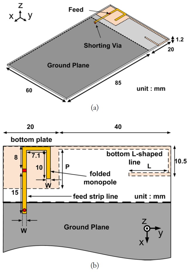
    In this study, a simple planar multiband antenna operating over the GSM/UMTS/LTE heptaband services is proposed. The proposed antenna consists of a folded monopole on the top plane and an L-shaped line with a coupling plate on the bottom plane. The folded line operates in the high-frequency bands including GSM1800 (1,710-1,880 MHz), GSM1900 (1,850- 1,990 MHz), UMTS (1,920-2,170 MHz), LTE class40 (2,305- 2,400 MHz), and LTE class7 (2,500-2,690 MHz), and the Lshaped line operates in the low-frequency bands including GSM850 (824-894 MHz) and GSM900 (880-960 MHz). High Frequency Structure Simulator (HFSS) v.15.0.0 by ANSYS is used for simulating the proposed antenna.

    II. ANTENNA GEOMETRY

    Fig. 1(a) shows the geometry of the proposed multiband antenna. The antenna is designed on the FR-4 substrate (εr = 4.4, tanδ = 0.02) with dimensions of 60 mm × 105 mm × 1.2 mm. The ground plane on the bottom plane of the substrate is connected to a feed strip line on the top plane by a shorting via. Fig. 1(b) shows the detailed design parameters of the proposed antenna. The antenna elements on the top plane are composed of the folded monopole and a feed strip line. These structures operate as a coupled feed line in the low-frequency band and as a radiator in the high-frequency band. The radiating elements on the bottom plane consist of a square plate coupled fed by a folded monopole and an L-shaped line for low-frequency operation.

    III. DESIGN PROCEDURE AND PARAMETRIC STUDY

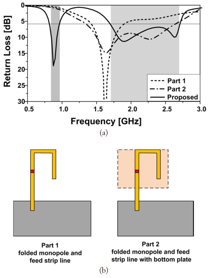
    To demonstrate the operating principle of the proposed antenna, a comparative study between two prototype antennas and the proposed antenna has been conducted. Fig. 2 shows the simulated return loss characteristics of two prototype antennas (Parts 1 and 2) and the proposed antenna. The single structure, which consists of the folded monopole and feed strip line on the top plane (Part 1), generates two resonances in the highfrequency band. However, the impedance matching condition at approximately 2,300 MHz does not satisfy the 6-dB return loss bandwidth requirement. In the case of the folded monopole and feed strip line with an additional square plate (Part 2), the impedance matching in the high-frequency band is improved. This prototype antenna has a wide bandwidth of approximately 1,260 MHz (1,360-2,620 MHz). To generate additional resonance in the low-frequency band, an L-shaped line is added on the bottom plane. The L-shaped line, which is fed by coupling between the bottom square plate and the top feed line, has a wide bandwidth characteristic in the low-frequency band. The simulated 6-dB return loss bandwidth of the proposed antenna is 142 MHz (818-960 MHz) in the low-frequency band and 1,007 MHz (1,700-2,707 MHz) in the highfrequency band.

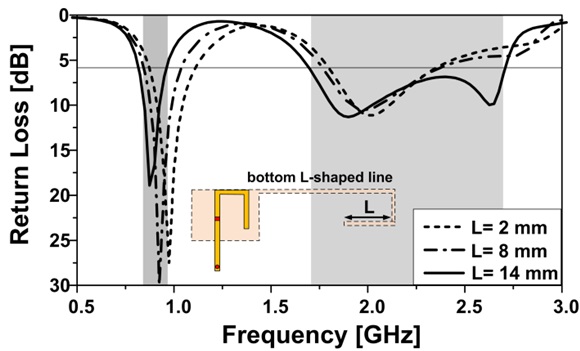
    Parametric studies and optimization are performed for impedance matching at each resonant frequency and to determine the resonant frequency. Fig. 3 shows the simulated return loss characteristic for various lengths of the L-shaped line, L. As L increases, the total length of the bottom structures, which operate in the low-frequency band, increases. Thus, the resonant frequency in the low-frequency band shifts toward the lowfrequency side. Fig. 4 shows the simulated return loss characteristics for various lengths P in the x-axis direction for the bottom square plate. As P increases, the high-frequency resonance at approximately 2,700 MHz shifts toward the lowfrequency side, whereas the low-frequency band is not affected. Fig. 5 shows the simulated return loss characteristics for various widths, W, of the folded monopole and feed strip line. As W increases, the overall matching condition in the high frequency band improves. However, as W increases, the effective current path of the folded monopole and feed strip line is shortened, and therefore, the resonant frequency at approximately 1,800 MHz shifts toward the high-frequency side. When the proposed antenna has dimensions of L = 14 mm, P = 14 mm, and W = 1.4 mm, the antenna satisfies 6-dB return loss bandwidth over the desired heptaband services.

    IV. RESULTS AND DISCUSSION

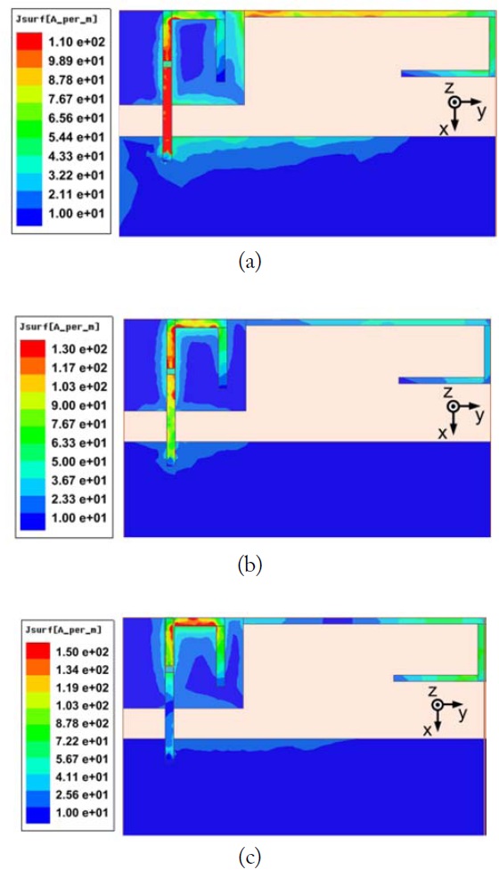
    Fig. 6(a)-(c) show the simulated surface current distributions of the proposed antenna at each resonant frequency. For lowfrequency resonance, the bottom L-shaped line operates actively owing to the electromagnetic coupling between the bottom plate and the top feed strip line. The total length of the current path is around a quarter-wavelength in the low-frequency band (875 MHz). In Fig. 6(b), the total current path, which generates the resonance at 1,900 MHz, consists of a folded monopole and a feed strip line. The length of the total current path is approximately 40 mm, which is a quarter-wavelength at 1.875 GHz. However, in Fig. 6(c), the surface current is strongly distributed only on the folded monopole structure. As the resonant length becomes shorter than the case in Fig. 6(b), resonance occurs at 2,650 MHz.

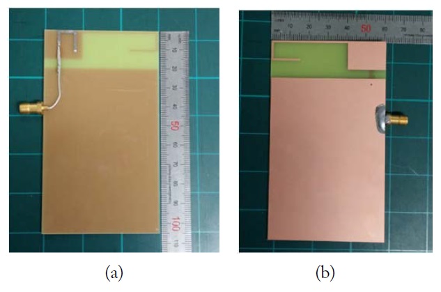
    Fig. 7 shows photographs of the implemented antenna. In the experiment, a 50-Ω coaxial line is used to excite the antenna. The outer and inner conductors of the coaxial cable are connected to the feed strip line and folded monopole structure, respectively.

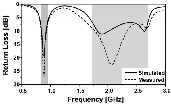
    Fig. 8 shows the simulated and measured return loss characteristics of the proposed antenna. The measured results agree well with the simulated results. However, the impedance matching level and resonant frequency at approximately 2.1 GHz do not agree well with the simulation because of fabrication errors. The measured 6-dB return loss bandwidth is 152 MHz (820-972 MHz) in the low-frequency band and 1,150 MHz (1,600-2,750 MHz) in the high-frequency band. The resulting bandwidth is wide enough to cover the desired heptaband services.

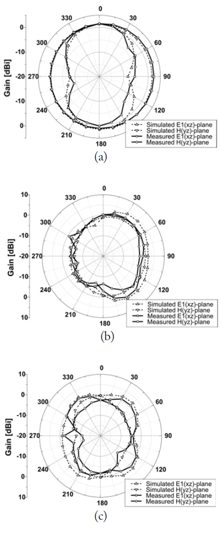
    Fig. 9 shows the measured far-field radiation patterns of the proposed antenna at each resonant frequency. In Fig. 9, the E1-plane corresponds to the xz-plane and the H-plane, to the yzplane. At a low frequency of 875 MHz, the proposed antenna shows omnidirectional radiation patterns in the H-plane. At high frequencies of 1,900 and 2,650 MHz, the proposed antenna shows nearly omnidirectional patterns. The measured radiation patterns are suitable for practical mobile communication systems.

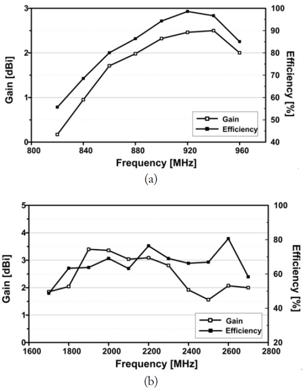
    Fig. 10. shows the measured radiation efficiencies and gains of the implemented antenna. The measured radiation efficiencies are approximately 55%-98% and 48%-80% in the lowand high-frequency bands, respectively. The measured gain varies from 0.17 to 2.46 dBi in the low-frequency band and from 1.56 to 3.4 dBi in the high-frequency band. The measured average gain varies from -2.55 to -0.06 dBi in the low-frequency band and from -3.13 to -0.94 dBi in the high-frequency band.

    V. CONCLUSIONS

    In this study, a simple planar heptaband antenna with a coupling feed for 4G mobile applications is proposed. For easy integration in various mobile devices, the proposed antenna has simple structures on both the top and the bottom planes. The measured 6-dB return loss bandwidths are wide enough to cover the desired LTE/GSM/UMTS heptaband services. The antenna has nearly omnidirectional radiation patterns at each resonant frequency. Based on the measured results, one can conclude that the proposed multiband antenna is a good candidate for 4G multiband mobile applications.

참고문헌
  • 1. Lin K. C., Lin C. H., Lin Y. C. 2013 "Simple printed multiband antenna with novel parasitic-element design for multistandard mobile phone applications," [IEEE Transactions on Antennas and Propagation] Vol.61 P.488-491 google cross ref
  • 2. Guo J., Zhou L., Sun B., Zou Y. 2012 "Magneto-electric monopole antenna for terminal multiband applications," [Electronics Letters] Vol.48 P.1249-1250 google cross ref
  • 3. Valkonen R., Ilvonen J., Icheln C., Vainikainen P. 2013 "Inherently non-resonant multi-band mobile terminal antenna," [Electronics Letters] Vol.49 P.11-13 google cross ref
  • 4. Zhang T., Li R., Jin G., Wei G., Tentzeris M. M. 2011 "A novel multiband planar antenna for GSM/UMTS/LTE/ Zigbee/RFID mobile devices," [IEEE Transactions on Antennas and Propagation] Vol.59 P.4209-4214 google cross ref
  • 5. Ban Y. L., Chen J. H., Li J. L. W., Wu Y. 2013 "Small-size printed coupled-fed antenna for eight-band LTE/GSM/ UMTS wireless wide area network operation in an internal mobile handset," [IET Microwaves, Antennas & Propagation] Vol.7 P.399-407 google cross ref
  • 6. Wong K. L., Tu M. F., Wu C. Y., Li W. Y. 2010 "On-board 7-band WWAN/LTE antenna with small size and compact integration with nearby ground plane in the mobile phone," [Microwave and Optical Technology Letters] Vol.52 P.2847-2853 google cross ref
  • 7. Wong K. L., Chen W. Y., Wu C. Y., Li W. Y. 2010 "Small size internal eight-band LTE/WWAN mobile phone antenna with internal distributed LC matching circuit," [Microwave and Optical Technology Letters] Vol.52 P.2244-2250 google cross ref
  • 8. Zhao X., Kwon K., Choi J. 2013 "MIMO antenna using resonance of ground planes for 4G mobile application," [Journal of Electromagnetic Engineering and Science] Vol.13 P.51-53 google cross ref
  • 9. Jeon S., Oh S., Kim H. H., Kim H. 2012 "Mobile handset antenna with double planar inverted-E (PIE) feed structure," [Electronics Letters] Vol.48 P.612-614 google cross ref
  • 10. Lee J., Sung Y. 2014 "Heptaband inverted-F antenna with independent resonance control for mobile handset applications," [IEEE Antennas and Wireless Propagation Letters] Vol.13 P.1267-1270 google cross ref
이미지 / 테이블
  • [ Fig. 1. ]  Configuration of proposed antenna: (a) perspective view and (b) detailed dimensions.
    Configuration of proposed antenna: (a) perspective view and (b) detailed dimensions.
  • [ Fig. 2. ]  Simulated return loss characteristics of proposed antenna for folded monopole and feed strip line (Part 1) and for folded monopole and feed strip line with bottom plate (Part 2). The dimensions of these reference antennas are shown in Fig. 1.
    Simulated return loss characteristics of proposed antenna for folded monopole and feed strip line (Part 1) and for folded monopole and feed strip line with bottom plate (Part 2). The dimensions of these reference antennas are shown in Fig. 1.
  • [ Fig. 3. ]  Return loss characteristics for various lengths of bottom L-shaped line.
    Return loss characteristics for various lengths of bottom L-shaped line.
  • [ Fig. 4. ]  Return loss characteristics for various lengths in x-axis direction for bottom square plate.
    Return loss characteristics for various lengths in x-axis direction for bottom square plate.
  • [ Fig. 5. ]  Return loss characteristics for various widths of folded monopole and feed strip line.
    Return loss characteristics for various widths of folded monopole and feed strip line.
  • [ Fig. 6. ]  Simulated surface current distributions of proposed antenna at (a) 875 MHz, (b) 1,900 MHz, and (c) 2,650 MHz.
    Simulated surface current distributions of proposed antenna at (a) 875 MHz, (b) 1,900 MHz, and (c) 2,650 MHz.
  • [ Fig. 7. ]  Photographs of implemented antenna: (a) top view and (b) bottom view.
    Photographs of implemented antenna: (a) top view and (b) bottom view.
  • [ Fig. 8. ]  Simulated and measured return loss characteristics of proposed antenna.
    Simulated and measured return loss characteristics of proposed antenna.
  • [ Fig. 9. ]  Simulated and measured far field radiation patterns of fabricated antenna at (a) 875 MHz, (b) 1,900 MHz, and (c) 2,650 MHz.
    Simulated and measured far field radiation patterns of fabricated antenna at (a) 875 MHz, (b) 1,900 MHz, and (c) 2,650 MHz.
  • [ Fig. 10. ]  Measured antenna gain and radiation efficiency of implemented antenna: (a) low-frequency band and (b) high-frequency band.
    Measured antenna gain and radiation efficiency of implemented antenna: (a) low-frequency band and (b) high-frequency band.
(우)06579 서울시 서초구 반포대로 201(반포동)
Tel. 02-537-6389 | Fax. 02-590-0571 | 문의 : oak2014@korea.kr
Copyright(c) National Library of Korea. All rights reserved.