Nano-carbon materials exhibit unique physical and chemical properties which make them attractive starting materials for applications including nanoelectronics, optics [1,2], and the preparation of various carbon composites. However, the physical and chemical properties of nano-carbon materials are extensively influenced by their assembled and dispersed structures. For example, carbon nanotubes (CNTs) are cylindrical one-dimensional carbon nanomaterials with a large aspect ratio, while graphene derivatives are two-dimensional carbon materials comprising
Liquid crystalline molecules can show spontaneous orientation, resulting from an excluded volume effect in a domain which has an averaged orientation-direction called “a director”. On a macroscopic level, because the director in each liquid crystalline domain is randomly oriented, they assume a multi-domain structure. The multi-domain structure of a liquid crystalline can be easily transformed into a mono-domain structure upon the application of an artificial external force, such as that produced from shearing, or electric or magnetic fields. In addition, the oriented direction of the mono-domains in the liquid crystalline can be reoriented simply by changing the direction of the applied shear force, electric or magnetic field. As a result of these self-assembling abilities and the responsiveness of the orientation direction to external forces, liquid crystallines are used to produce macroscopically aligned states in many materials. In particular, sp2-conjugated nanomaterials such as conjugated polymers [3-6], porphyrin derivatives [7,8], fullerenes [9,10], and graphenes [11-14], which are difficult to organize and align because of extensive van der Waals interactions, are efficiently organized by using liquid crystalline templates or by embedding liquid crystallinity [15].
In this work, we review the recent advances in the novel preparation of liquid crystalline nano-carbon materials, focusing on CNTs and graphene derivatives, and the liquid crystalline spinning method for producing continuous nano-carbon fibers.
2.1. Liquid crystalline carbon nanotubes
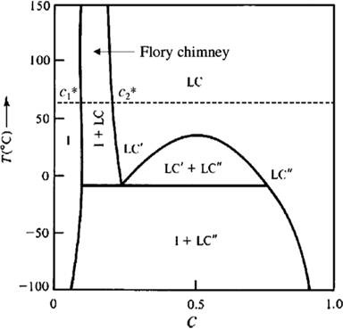
CNTs are quite complex systems. From a theoretical point of view, CNTs are thought to be models of straight, long, rigidrodlike particles. The liquid crystallinity of CNTs has been investigated using the steric theory of rigid-rodlike liquid crystals [16-18] and by analyzing phase diagrams using the simple Flory chimney [19].
The mesogenicity of a rodlike object, which is the ability to form liquid crystalline phases, depends mainly on its straightness and aspect ratio (length/diameter ratio). According to the rigid rod theory, liquid crystallinity begins to appear at a weight fraction of about 3.3Fd/L, where F, d, and L are density, rod diameter, and length of the rod, respectively. The polymer/solvent equilibrium diagram (Fig. 1) illustrates that the liquid crystalline and isotropic phases in equilibrium are divided by the Flory chimney, spreading out over a set range of composition, whose bounds depend on the mesogenicity of the polymer and the strength of the interaction between polymers separated by temperature [20-22]. If the polymers are widely polydispersed, the polymers whose molecular weights are low enough to lower their mesogenicity (i.e., lengths shorter than their persistence length) will diffuse prior to the isotropic phase, which is disordered. Consequently, a measure of size fractionation will take place between the two phases of the Flory chimney in the polymer/solvent equilibrium diagram. If the phases are physically divided, the liquid crystalline phase can disappear and be refractionated by the further addition of solvent. Then, this process can be repeated sequentially to enhance the mesogenicity of the species forming the liquid crystalline phase. Because CNTs can be exceptionally long, the fractionation of CNTs is possible if their length ranges are within length/diameter ratios greater than 100:1 [23].
Up to now, three methods have been used to prepare liquid crystalline CNTs: acid oxidation [24,25], polymer wrapping [26-29], and superacid protonation [30,31]. Acid oxidation is an efficient method of modifying the CNT surface by introducing functional groups [32-35]. H2SO4 and HNO3 are commonly used in this method [31,36], and scissions also occur simultaneously in the CNT with this method. As a result, many fractions of CNTs with various sizes can be made. A centrifugation or precipitation process is necessary to classify them by size.
Polymer wrapping is another method used to fabricate liquid crystalline CNTs. The process enables CNTs to be dispersed effectively in solvents without damage because the polymer allows them to disperse as individual units. A number of polymers have been investigated for the polymer wrapping method, such as conjugated polymers [26], amphiphilic block copolymers [27], polyelectrolytes [28], and biopolymers [29]. However, CNTs prepared by this method have inferior properties and limited applications due to intermolecular defects which remain after polymer wrapping.
Another method to improve the dispersion of CNTs and prepare liquid crystalline CNTs is the superacid protonation method reported by Pasquali’s group [31,36]. With this method, the amount of damage on the surfaces of the CNTs can be greatly reduced, and liquid crystalline CNTs can be made without any additives. Consequently, this method is appropriate for manufacturing CNT fibers, and is considered superior to other methods in that regard. In this method, CNTs are dispersed as individual components in superacids such as 100% H2SO4, oleum, methanesulfonic acid (MSA), trifluoromethanesulfonic acid (triflic acid), and chlorosulfonic acid (CSA) [31,36]. Among these, CSA has been considered the most effective superacid because it only dissolves the CNTs [36-38].
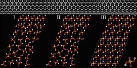
In Fig. 2, the single-walled carbon nanotube (SWNT)-templated crystallization of H2SO4
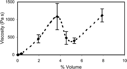
The protonation in the sidewalls of SWNTs reduces wall-to-wall van der Waals interactions and enhances the dispersion [30,37]. The viscosity of the SWNTs solution in 102% H2SO4 plotted against concentration is shown in Fig. 3. When the concentration becomes higher, there is a rapid increase in the viscosity of the solution until the concentration reaches a “critical concentration,” after which the viscosity decreases drastically. The increase is an expected result because viscosity tends to rise in an isotropic solution as the concentration becomes higher. From the critical concentration, a nematic phase starts to form and the viscosity begins to drop, exhibiting the low-viscosity behavior of nematic liquid crystals. Such behavior is particularly useful since it allows preparation of a solution containing relatively high proportions of composites, and is suitable for applications.
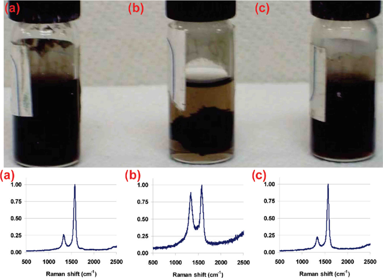
Crystallinity is another key parameter to study in liquid crystalline CNTs prepared by the superacid method [38,40]. Fig. 4 shows the Raman spectra of SWNTs, and the
2.2 Liquid crystalline spinning of CNTs
Individual nano-carbon materials have excellent properties [41-50]. For example, the properties of individual nano-carbon materials are higher than those of commercially available high-performance fibers [51-55]. However, in order to achieve these properties on a macroscopic level, elaborate techniques are needed to integrate the individual nano-carbon materials into a large scale. Liquid crystalline spinning is one of these techniques, which involves bathing the nano-carbon materials and producing liquid crystallinity through wet spinning. This method has advantages for fabrication of highly-oriented fibers, but it is hard to obtain liquid crystalline phases because the fiber spinning step is quite slow.
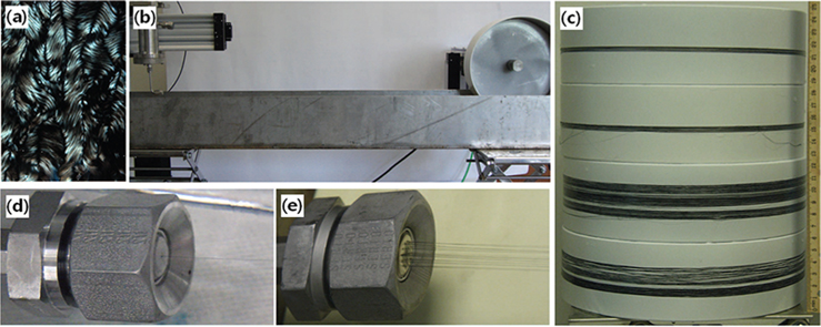
The term ‘liquid crystalline spinning by superacids’ was first used in 2004 when Ericson et al. [56] reported that a CNT fiber had been successfully fabricated by this method. The process began with the dispersion of SWNTs which had been produced by the high-pressure decomposition of CO (HiPco) [57,58] and purified in 102% H2SO4 (2.0 wt% excess SO3). Well-aligned continuous macroscopic fibers were produced without any surfactant or polymers structure. The
Optimal morphologies (alignment, packing density, content of impurities, and high-quality molecular constituents) are crucial to the properties of CNT fibers.
The mechanical properties of CNT fibers are considered to depend on the production of long, thin (usually, length >50 μm, diameter <3 nm), defect-free, and highly single-walled CNTs.
3.1 Liquid crystalline graphene oxide
Graphene oxide (GO) is defined as the oxidized form of a graphene monolayer platelet [60-67]. The mass production of GO sheet involves the oxidation of graphite to GO and chemical exfoliation [68-70]. After the oxidation, the graphene is exfoliated and functionalized by carboxylic, carbonyl, and hydroxyl groups. These groups create hydrophilicity on the surface of the GO and improve the dispersion and stability of the GO in a polar solvent without any additive [71-73].
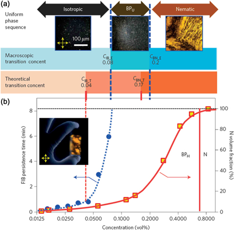
The phase transitions of the GO are affected by its aspect ratio (width/thickness ratio). Onsager’s excluded volume theory predicts lyotropic phase transitions in suspensions of rod-like or disk-like particles by calculating the total free energy of the system including the excluded volume effect of particles [16,74]. Based on a model system of infinitely thin hard platelets [75,76], the critical concentrations of the isotropic-nematic biphasic region were suggested to be
and
where
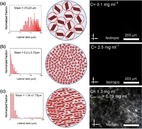
Recently, a novel process to prepare ultra-large sized GO was developed using pre-exfoliation of graphite flakes [79,80]. The high aspect ratio (>30,000) of the GO suspensions led to phase transitions even at a GO concentration as low as ≈ 1.0 mg/mL (0.1 wt%). In addition, liquid crystallinity was induced in isotropic (lower than the critical concentration) small-sheet GO dispersions by introducing a small amount of ultra-large GO sheets into it (Fig. 7) [81].
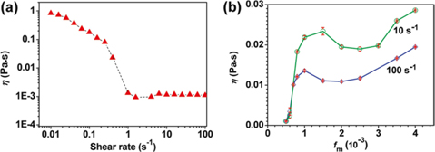
The rheological properties of liquid crystalline GO suspension are similar to those of liquid crystalline CNT suspension [71,77,82]. In Fig. 8, the rheological behavior of GO dispersed in DI-water is shown. The viscosity of GO suspension decreases as shear stress increases, and depends on the GO composition and molecular arrangements in the suspension. The viscosity shows non-monotonic behavior as volume fraction (φ) increases. At a low volume fraction the GO suspension is in an isotropic phase, and the viscosity increases until the volume fraction reaches the critical point. Then, the viscosity goes down and increases again. The minimum viscosity approximately corresponds to that of a GO suspension where a nematic phase forms entirely.
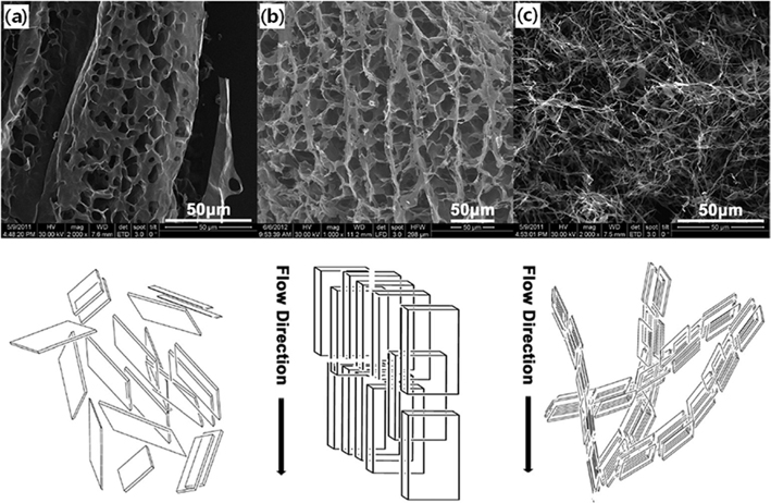
This liquid crystalline behavior exhibited by a GO suspension agrees well with an optical characterization which measured the liquid crystalline GO suspension by quenching it in liquid N2 and subsequent freeze-drying. Although there is an ordered structure inand alignment of the GO sheets in the frozen suspension, as shown in Fig. 9a, it reveals that a larger and more aligned structure can be achieved with a flowing suspension, as shown in Fig. 9b and c. Interestingly, the planes of the self-assembled layers are parallel to the direction of flow.
3.2 Liquid crystalline spinning of GO
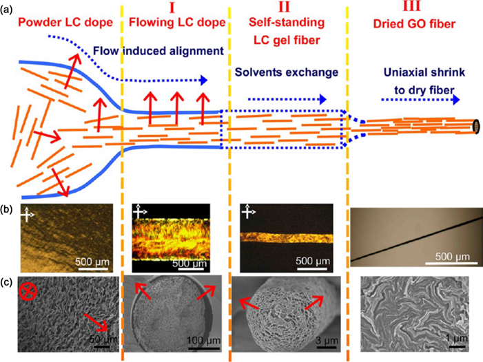
In 2011, Xu and Gao [83] reported that macroscopic GO fibers had been prepared by continuous spinning of an aqueous suspension of the liquid crystalline GO (Fig. 10), and the optical textures of the liquid crystalline phases of the GO (nematic, lamellar, chiral) and their corresponding structural models were investigated. Furthermore, a lot of methods for fabricating graphene-based composites by liquid crystalline spinning have been reported, including fiber [83-87], aerogel [88], film [89], and network [90] processes.
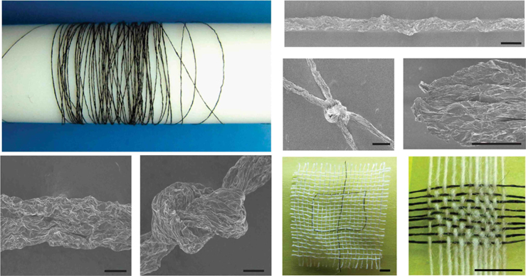
Generally, 2D colloids are considered to be inadequate for continuous spinning because the interactions between solid-like flakes are weak, and the solubility of colloids is insufficient. However, the alignment of GO sheets by the intrinsic lamellar order of liquid crystalline GO provides strong interactions between neighboring sheets, which are responsible for their strong mechanical strength [91], and GO sheets with large sizes provide a considerable improvement in mechanical performance (Fig. 11) [84,85]. Control of coagulation baths has been applied as another method to improve the properties of GO fibers [86,87].
Since the successful fabrication of fullerene in 1996 [44], a number of nano-carbon materials have been produced by different methods, especially during the last decade, including the fabrication of liquid crystalline CNTs by spinning from superacids in 2004 [56] and the continuous production of macroscopic fibers from liquid crystalline GO in 2011 [83]. In addition, various efforts have been made to improve the production processes of nano-carbon fibers and to establish their post-treatment processes. As a result, the high mechanical, electrical, and thermal properties of individual nano-carbon materials have been incorporated into the fibers. Nano-carbon fibers have a good ratio of strength to weight because of their low density. When they are applied to composites, they should have high strength, comparable to those of super-strong fibers or individual nano-carbon materials. Therefore, it is expected that these liquid crystalline spinning methods can be used for the mass production of nano-carbon fibers and the spun fibers can also be used in practical carbon materials.

![Phase diagram for a polymer/solvent equilibrium in a lyotropic liquid crystal solution. LC: liquid crystalline. Reprinted from Zhang et al. Nano Lett, 6, 568 (2006), with permission of ACS Publications [19].](http://oak.go.kr/repository/journal/17399/HGTSB6_2015_v16n4_223_f001.jpg)
![Schematic illustration of the crystallization of H2SO4 templated by single-walled carbon nanotube. Reprinted from Zou et al. J Am Chem Soc, 127, 1640 (2005), with permission of ACS Publications [39].](http://oak.go.kr/repository/journal/17399/HGTSB6_2015_v16n4_223_f002.jpg)
![Viscosity against concentration of a single-walled carbon nanotubes solution in 102% H2SO4 at a shear rate of 0.1 s?1. Reprinted from Davis et al. Macromolecules, 37, 154 (2004), with permission of ACS Publications [30].](http://oak.go.kr/repository/journal/17399/HGTSB6_2015_v16n4_223_f003.jpg)
![Image and Raman spectra of single-walled carbon nanotubes (SWNTs) solutions with different defect levels in chlorosulfonic acid. (a) Low-defect SWNTs (60 μm), (b) high-defect SWNTs, (c) low defect SWNTs (100 μm). Reprinted from Parra-Vasquez et al. ACS Nano, 4, 3969 (2010), with permission of ACS Publications [38].](http://oak.go.kr/repository/journal/17399/HGTSB6_2015_v16n4_223_f004.jpg)
![(a) Image of a birefringent fiber spinning dope (3 wt% carbon nanotube in chlorosulfonic acid). (b) Set-up for spinning. The fluid is pressed out from the spinning chamber (left) through a spinneret submerged in a coagulation bath; the fiber is continuously collected on the winding drum (right). (c) Winding drums with collected fibers (100 to 500 m on each drum). (d,e) Close-up view of a single- and 19- filament spinning. Reprinted from Behabtu et al. Science, 339, 182 (2013), with permission of American Association for the Advancement of Science [59].](http://oak.go.kr/repository/journal/17399/HGTSB6_2015_v16n4_223_f005.jpg)
![Theoretical and experimental phase diagram against volume fraction in a graphene oxide suspension. Reprinted from Shen et al. Nat Mater, 13, 394 (2014), with permission of Nature Publishing Group [78].](http://oak.go.kr/repository/journal/17399/HGTSB6_2015_v16n4_223_f006.jpg)
![Introduction of ultra-large graphene oxide (GO) sheets into fully isotropic and non-spinnable GO dispersion. Reprinted from Jalili et al. Mater Horiz, 1, 87 (2014), with permission of Royal Society of Chemistry [81].](http://oak.go.kr/repository/journal/17399/HGTSB6_2015_v16n4_223_f007.jpg)
![(a) Shear viscosity against shear rate and (b) shear viscosity against volume fraction. Reprinted from Xu and Gao. ACS Nano, 5, 2908 (2011), with permission of ACS Publications [71].](http://oak.go.kr/repository/journal/17399/HGTSB6_2015_v16n4_223_f008.jpg)
![Scanning electron microscope images of freeze-dried graphene oxide sheets and corresponding diagram of self-assembled structures from a frozen solution of 5 mg/mL (0.5 wt%) (a), and a flow induced solution of 5 (b) and 1 mg/mL (0.1 wt%) (c). Reprinted from Yang et al. Langmuir, 29, 8103 (2013), with permission of ACS Publications [77].](http://oak.go.kr/repository/journal/17399/HGTSB6_2015_v16n4_223_f009.jpg)
![Macroscopic neat graphene oxide (GO) fibers and chemically reduced GO fibers. Reprinted from Xu and Gao. Nat Commun, 2, 571 (2011), with permission of Nature Publishing Group [83].](http://oak.go.kr/repository/journal/17399/HGTSB6_2015_v16n4_223_f010.jpg)
![Illustration of structural evolution (a) and images in the spinning process (b,c). LC: liquid crystalline. Reprinted from Xu and Gao. Acc Chem Res, 47, 1267 (2014), with permission of ACS Publications [91].](http://oak.go.kr/repository/journal/17399/HGTSB6_2015_v16n4_223_f011.jpg)