Solar energy is the simplest and most abundant source of renewable energy. A solar-energy, photo-thermal-conversion application is used for solar space heating and cooling and in industrial settings [1]. For these purposes, it is necessary to study and develop new types of solar selective absorbers and materials with even higher efficiencies. An effective solar absorber should have a high absorptance in the wavelength range of 0.3 μm to 2.5 μm, and a low emittance above a wavelength of 2.5 μm at higher operating temperatures [2]; therefore, the coatings of the solar absorber must have a high absorptance over the visible wavelength range and a low emittance in the infrared region. In recent years, further attention has been focused on the solar selective absorber for solar heating applications due to the depletion of fossil fuels. A large number of solar selective coatings have been fabricated using a variety of methods such as electro-deposition; sol-gel; thickness-sensitive, spectrally selective paints; spray pyrolysis; evaporation; ion plating; pulsed laser deposition; and magnetron sputtering [3-11]. Among these methods, reactive magnetron sputtering is advantageous in a comparison with other types of deposition due to a number of merits [12]. First, sputtering deposition is a widely used method for solar-material coating on a large-area substrate. Secondly, the method is adaptable to various kinds of thin-film materials such as metals, oxides, nitrides, organic materials, and ceramics. Thirdly, reactive sputtering that uses a metal target can easily control the composition of a thin film with the components and contents of injected gases; furthermore, the method is advantageous due to its high deposition rate and an ability to regulate the thicknesses of sputtered films.
To improve the optical properties and thermal stability of solar absorbers, a thin-film manufacturing trend involving the use of a large number of composite materials with W, Mo, Co, and Cr has emerged. Sputtered-Cr thin films have an excellent substrate-adhesion property and a high erosion resistance [13]; furthermore, Cr-alloy films easily react with several gases and are widely used in the application of hard coatings.
The suitable structure of a solar absorber allows for the absorption of solar radiation with a low thermal emittance. This absorption effect is gained from the usage of the following multilayered structure [14-16]: a metal layer with a high reflectivity in the infrared region, a cermet layer to absorb the incident solar radiation, and an anti-reflection layer to reduce the reflection loss. Moreover, it is not possible to obtain a high absorptance with a single homogeneous cermet layer. The solar selective absorber must be comprised of a more complex structure, whereby an appropriate structure consists of a cermet film with a gradedmetal concentration profile and a corresponding higher metalvolume fraction on the substrate. With this structure, it is possible to complete both the internal optical absorption of the composite films and high solar performances.
In this study, Al2O3/AlCrNO/Al thin films were deposited on aluminum substrates using a DC-reactive magnetron sputtering technique. The material and optical characteristics of the solar absorber coating were investigated using experimental equipment. The crystallinity and surface properties were estimated by an X-ray diffractometer (XRD) and field emission scanning electron microscopy (FE-SEM). The exact composition and optical properties of the thin films were measured using Auger electron spectroscopy (AES) and a UV-Vis-NIR spectrophotometer.
The anti-reflection layer and multi-layer cermet films of the solar absorber were subsequently prepared using the DC-reactive magnetron sputtering system. The Al:Cr (5 wt.% to 10 wt.%) target with a purity of 99.995% was sputtered in Ar (99.99%)-, N2 (99.99%)-, and O2 (99.995%)-mixed gases. The thin films were deposited under a base pressure of 3 × 10⁻⁶ Torr and a total operating pressure in the range of 10 mTorr to 70 mTorr. The flow rates of the Ar, N2, and O2 gases were controlled separately using mass-flow controllers. The Al2O3 anti-reflection layer was prepared with Ar + O2 gas under a pressure of 20 mTorr. Regarding the cermet multi-layer films, the volume fraction of the metal component was controlled by gas mixtures of Ar and (N2 + O2).
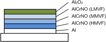
The parameters for the deposition of the coating of the multi-layer solar selective absorber are listed in Table 1. A schematicdiagram structure of the Al2O3/AlCrNO/Al multi-layer absorber is shown in Fig. 1, and the top anti-reflection layer locates a transparent Al2O3 for the attainment of a higher solar absorption. The absorbing film consists of three homogeneous AlCrNO cermet layers with different metal-volume fractions. The layer (third cermet layer) near the substrate has a high metal-volume fraction (HMVF), the centered layer has a medium metal-volume fraction (MMVF), and the layer near the anti-reflection layer has a low metal-volume fraction (LMVF). An Al metal as an infrared reflective layer is located on the substrate, reducing the substrate emittance.
[Table 1.] Sputtering conditions of as-deposited solar absorber films.
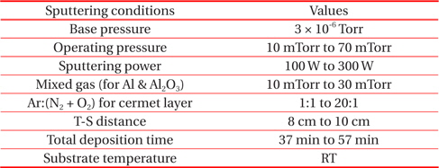
Sputtering conditions of as-deposited solar absorber films.
The crystallinity of the resulting films was checked using X-ray diffraction, whereby CuKα radiation in the range of 2 θ=10° to 2 θ=90° was used. The reflectance and transmittance of the absorbing thin films were measured at the wavelength range of 0.3 μm to 2.5 μm using a Hitachi UH4150 UV-Vis-NIR spectrophotometer. The solar absorptance of the multi-layer was calculated using a standard AM1.5 solar spectrum.
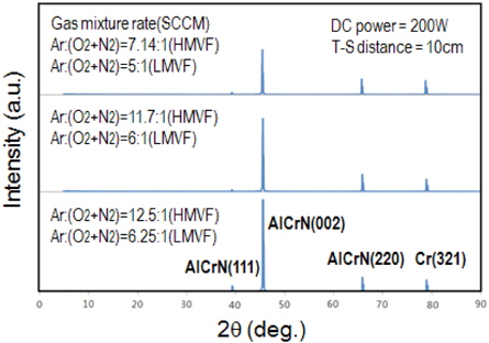
Figure 2 shows the XRD patterns of the Al2O3/AlCrNO/Al multi-layer absorber at different gas mixtures of Ar and (N2 + O2). The gas-mixture rate of the HMVF and LMVF cermet films increased gradually. A high intensity peak centered at 2 θ=45.60°, and other weaker peaks at 2 θ=38.18°, 2 θ=65.89°, and 2 θ=78.94°, can be seen in Fig. 2.
The strong peak of 2 θ=45.60° can be attributed to the AlCrN (002) plane, and it increased with the increasing gas-mixture rates of the HMVF and LMVF films. The other peaks (2 θ=38.18°, 2 θ=65.89°, and 2 θ=78.94°) are due to the AlCrN (111) plane, AlCrN (220) plane, and Cr (321) plane, respectively.
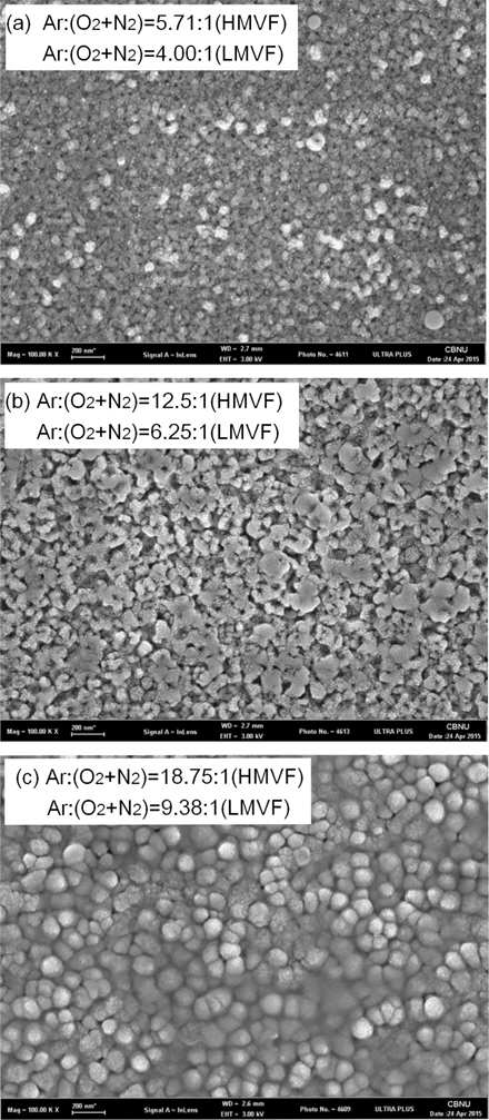
FE-SEM images of the AlCrNO cermet multi-layer films at different gas mixtures of Ar and (O2 + N2) are shown in Fig. 3. The gas-mixture rate of the MMVF on the three layers of the cermetabsorber films is exactly the middle value between the HMVF and LMVF. The surface of the solar-absorber coating exhibits a smooth and dark violet color. From the resulting FE-SEM images, the grain sizes of the cermet thin films grew gradually with an increasing gas-mixture rate; the grain sizes are approximately 55 nm, 85 nm, and 115 nm. These results match properly with the crystalline property of the AlCrNO cermet films, as shown in the XRD results of Fig. 2.
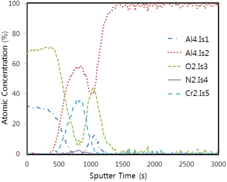
Figure 4 shows the AES depth-profile analysis of the Al2O3/AlCrNO/Al multi-layer absorber.
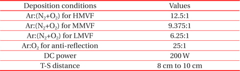
Table 2 explains the deposition conditions of the cermet multi-layer coating as shown in Fig. 4. The profile coating consists of an Al2O3 anti-reflection layer, an AlCrNO cermet multi-layer, and an Al reflector layer from surface to substrate. From the AES-analysis result, the depth profile shows the peaks of the Al, O2, N2, and Cr elements, and that the concentrations of the Al and Cr elements increased gradually, whereas the oxygen element decreased from the surface to the substrate; this trend is essentially in agreement with the deposition conditions indicated in Table 2. From surface to substrate, the gas-mixture rate of the cermet multi-layer increased sequentially so that the multi-layer was changed from the LMVF layer to the HMVF layer.
[Table 2.] Deposition conditions of cermet film as shown in Fig. 4.

Deposition conditions of cermet film as shown in Fig. 4.
The oxygen concentration increased relatively between the Al reflector and Al substrate due to the formation of an oxide layer on the pristine Al substrate; also, due to the high sensitivity of the AES instrument, the oxygen element is present in all of the layers. Moreover, the examination of the deposition processes revealed that the oxygen contamination most likely came from either the residual oxygen in the deposition chamber or from the sputtering Al target.
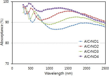
Figure 5 shows the different absorptance spectra of the AlCrNO cermet films with a variety of gas-mixture rates.
Table 3 shows the detailed sputtering conditions of the AlCrNO cermet films, as shown in Fig. 5, and exhibits the absorptance and reflectance values of 4 samples. Table 3 shows that the metal volume fraction (MVF) became high, thereby increasing the gas-mixture rate of Ar and (O2 + N2) on the cermet films. The absorptance curves of the multi-layer cermet films in Fig. 5 are approximately 90%, and slightly different traces existed in the wavelength range of 0.3 μm to 2.5 μm. When the gas-mixture rates increased, the absorptance tended to increase generally, whereas the reflectance decreased. The optimized value of the optical properties is achieved in sample 4 with an absorptance of 95% and a reflectance of 3.85%.
[Table 3.] Deposition conditions and optical properties of cermet samples, as shown in Fig. 5.
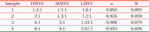
Deposition conditions and optical properties of cermet samples, as shown in Fig. 5.
In this paper, the anti-reflection-layer and multi-layer AlCrNO cermet films of the solar absorber were prepared using a DC-reactive magnetron sputtering system. The exact structure of the as-deposited multi-layer films is Al2O3/AlCrNO (LMVF)/AlCrNO (MMVF)/AlCrNO (HMVF)/Al/substrate. Three absorbing multi-layer coatings were prepared using the Ar and (N2 + O2) gas-mixture rates. The XRD results show that the strong peak of the AlCrN (002) plane increased with an increasing gas-mixture rate. As the gas-mixture rate increased, the grain sizes of the cermet thin films grew gradually, and this is consistent with the crystallinity of the AlCrNO cermet films, as shown in the XRD results. As the gas-mixture rates increased, the absorptance values tended to also increase. The optimized value is achieved in sample 4 with an absorptance of 95% and a reflectance of 3.85%.