In fourth-generation (4G) mobile networks such as longterm evolution advanced (LTE-Advanced) or mobile world interoperability for microwave access (WiMAX) [1], base stations composed of a central digital unit (DU) and remote radio units (RUs) are widely used since they have several advantages such as deployment flexibility and low outside installation cost [2]. In the base station systems, the common public radio interface (CPRI) [3], open base station architecture initiative (OBSAI) [4], or open radio interface (ORI) [5] is currently used as the link between the DU and the RU. This network is also called a centralized (or cloud) radio access network (C-RAN) [6]. In such an interface, the analog radio signals are sampled, quantized, and then transmitted through a digital optical fiber transmission. This is sufficient to support several radio channels having a bandwidth of 20 MHz [7]. However, future mobile networks are likely to have wider channel bandwidths for higher channel throughput and each RU will need to support several sectors and more than 8 × 8 multiple-input multipleoutput (MIMO) schemes [8]. Hence, to support the future mobile networks, tens of CPRI or OBSAI interfaces of >5 Gb/s will be required.
Therefore, the radio over fiber (RoF) technology has been proposed to support the increased link capacity between the DU and the RU more economically [9-15]. In an RoF system, analog radio signals are transmitted as analog optical transmission. In some RoF systems, multiple analog radio signals are transmitted using several subcarrier frequencies [11]. Although RoF is a promising technology, the signal quality can deteriorate easily because of the nonlinearity in the RoF transmission. This usually limits the performance of RoF systems [16] and makes it difficult to meet the error vector magnitude (EVM) requirement of the LTE-Advanced standard [17]. Thus far, to overcome the nonlinearity in RoF systems, several approaches have been proposed [18-20]. However, the previous methods have focused only on the nonlinearity of the transmitter or a specific nonlinear effect.
In this paper, we propose a nonlinearity detection and compensation scheme using a monitoring channel in RoF systems. The proposed method can detect and compensate for the whole nonlinearity from the transmitter to the receiver. The proposed scheme uses a monitoring channel to send a reference signal to monitor the nonlinearity in the RoF transmission periodically. At the receiver, the transmitted monitoring channel is compared with the original reference signal so as to detect the nonlinearity. Then, the detected nonlinearity is compensated using an inverse function at the receiver. The proposed scheme can reduce the EVM degradation induced by the nonlinearity in RoF systems.
Fig. 1(a) shows a typical RoF scheme. In the transmitter part, each channel is modulated with a different radio signal and a different subcarrier frequency. The radio channels are multiplexed using frequency division multiplexing (FDM) and modulate a laser without an analog-to-digital conversion. The output of the laser is an analog optical signal and is transmitted in an optical fiber channel. In the receiver part, each channel is demodulated after band-pass filtering (BPF) with the center frequency of each subcarrier.
Fig. 1(b) shows the proposed RoF scheme using a monitoring channel to detect and compensate for the nonlinearity of the RoF system. In the proposed RoF system, a monitoring channel is added in the transmitter and is modulated with a reference signal. In this study, a simple sine wave is assumed to be the reference signal. In the transmitter, the radio channels and the monitoring channel are multiplexed using FDM. The FDM analog signal is transmitted through an optical fiber transmission system that includes a laser driver, a laser, and an optical fiber. Even though only a monitoring channel is assumed in this study, several monitoring channels can be used in the application depending on the frequency band.
The FDM analog signal containing the radio channels and the monitoring channel is distorted by the nonlinearity in the RoF transmission. At the receiver part, the monitoring channel is demodulated and compared with the original reference signal, which is the same as the reference signal at the transmitter. As a result, the nonlinear function in the transmission can be detected.
After detecting the nonlinear function in the RoF transmission, a reverse function of the detected nonlinearity is applied to the compensator of the radio channels. Each radio channel is demodulated after the compensation.
To investigate the performance of the proposed RoF scheme, computer simulations are conducted with a commercial simulator (VPItransmissionMaker; VPIphotonics Inc, Norwood, MA, USA). Table 1 shows the simulation conditions for ordinary radio channels. In the simulation, five orthogonal frequency division multiplexing (OFDM) radio channels with subcarrier frequencies of 2.0, 2.1, 2.2, 2.3, and 2.4 GHz, respectively, are assumed. The signal bandwidth of each radio channel is 20 MHz; the fast Fourier transform (FFT) size of the radio channels is 64; and the quadrature amplitude modulation (QAM) order of the radio channels is 16. The signal pattern is a pseudo-random binary sequence (PRBS).
[Table 1.] Simulation conditions of radio channels
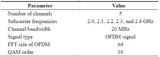
Simulation conditions of radio channels
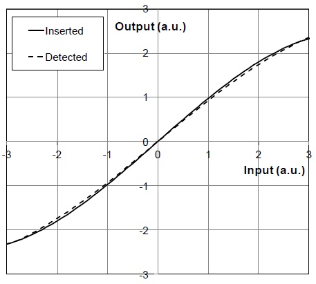
Table 2 shows the parameters of the inserted monitoring channel. To avoid frequency beating with the ordinary radio channels, a subcarrier frequency of 500 MHz is assumed. As a reference signal, a 1-MHz sine wave is modulated in the subcarrier through amplitude modulation. The amplitude of the monitoring channel is adjusted to cover the maximum amplitude of the FDM radio channels. At the receiver, the monitoring channel is demodulated after BPF with a center frequency of 500 MHz. To emulate the nonlinearity in the RoF system, a third-order polynomial nonlinear function is inserted into the transmitter laser. The nonlinearity inserted into the laser is plotted as a solid line in Fig. 2.
[Table 2.] Simulation conditions of the monitoring channel
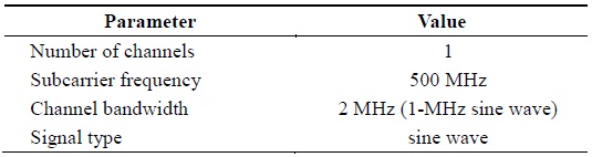
Simulation conditions of the monitoring channel
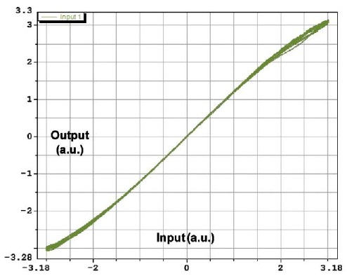
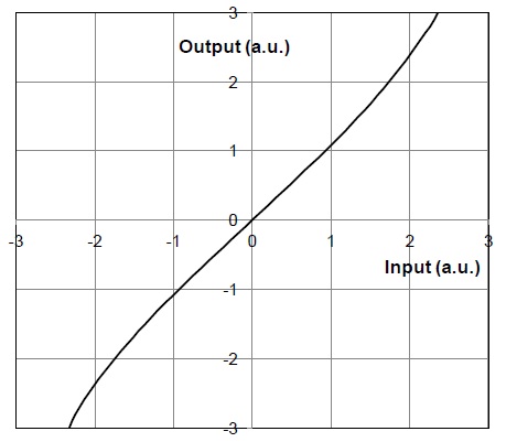
The ordinary radio channels and the monitoring channel are distorted by the nonlinear function. To detect the nonlinear function, the received monitoring signal at the receiver is compared with the reference signal. Fig. 3 shows the raw data of the relationship of the received monitoring signal (y-axis) and the reference signal (x-axis). To eliminate the noise of the raw data shown in Fig. 3, the data are averaged. Finally, the nonlinearity can be detected without noise after the averaging process and is plotted as a dashed line in Fig. 2. Here, we observe that the nonlinearity detected by the monitoring channel is almost the same as the inserted nonlinearity. Then, the inverse function of the nonlinearity can be made by switching the x-axis and the yaxis of the detected nonlinearity. This is shown in Fig. 4. The inverse function is applied to the compensator, and the received radio signals are compensated according to the compensating function.
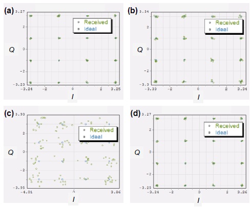
Fig. 5 shows the signal constellation of the radio channel at a 2.2-GHz subcarrier when the nonlinearity does not exist, the nonlinearity exists, a monitoring channel is added, and the nonlinearity is compensated after removing the monitoring channel. Table 3 summarizes the EVM results of the radio channel depending on the RoF system conditions in Fig. 5. Before the nonlinearity is inserted into the RoF system, the EVM is only 1.4%. After the nonlinearity is inserted, the EVM increases to 2.8%. When the monitoring channel is added to detect the nonlinearity, the EVM increases to 15.3%. Because the monitoring channel severely increases the EVM of the radio channel, it should be removed after detecting the nonlinearity. After compensating for the nonlinearity, the EVM becomes 1.5%, which is almost the same as in the case without the nonlinearity (1.4%).
[Table 3.] Results of nonlinearity compensation
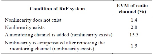
Results of nonlinearity compensation
These results show that the signal quality degradation caused by the nonlinearity in the RoF system can be detected and compensated effectively. However, because the monitoring channel deteriorates the signal quality of radio channels, we think that the monitoring channel should be used for a short time to detect the nonlinearity and should be removed after detecting the nonlinearity. The monitoring channel can be used periodically to detect the change in the nonlinearity because the nonlinearity in RoF systems can be changed with time.
Nonlinearity reduction is one of the major issues in RoF systems. In this paper, we have proposed an RoF scheme using a monitoring channel to detect and compensate for the nonlinearity in an RoF system. The transmitted monitoring signal is compared with the reference signal to detect the nonlinearity. The inverse function of the detected nonlinearity is used as the compensating function at the receiver. Our simulation results have shown that the EVM degradation induced by the nonlinearity can be almost removed by the proposed scheme. The proposed scheme is also useful to detect and compensate for the change in nonlinearity with time.