Since the development of the first wireless sensor network (WSN), named the Sound Surveillance System, by the United States Military in the 1950s to detect and track Soviet submarines, many advanced technologies have been added to modern WSNs. These networks are widely used in military, science and technology, industrial, and consumer applications [1]. Further, freeze drying is widely used in the manufacture of pharmaceuticals, biotech products, and emergency food supplies [2]. Since the fluid dynamics in freeze dryers determines product quality, it is important to monitor and control environmental factors, such as temperature, humidity, and pressure in freeze dryers.
Some research activities to improve the performance of freeze dryers can be found in the literature. For instance, a low-power wireless temperature monitoring system has been proposed for a freeze dryer in [3]. Further, in an effort to measure the temperature variation of a vial in a freeze dryer, a sputtered thermocouple array that can be installed on the vial has been developed [4]. In the freeze drying process, the pressure in a freeze dryer is as important as the temperature in the freeze dryer, as reported in [5]. Therefore, both pressure and temperature should be monitored simultaneously.
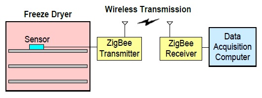
In this study, we designed a WSN for a freeze dryer, as shown in Fig. 1, and implemented it by using a ZigBee/IEEE 802.15.4 wireless interface and a single sensor module that includes a pressure and temperature sensor. The performance of the implemented WSN for a freeze dryer was evaluated using a commercial laboratory freeze dryer.
II. DESIGN OF WIRELESS SENSOR NETWORK
In order to develop a WSN for a freeze dryer, certain hardware and software design techniques are required.
Since a wireless sensor node needs to be installed in a closed space, that is, the freeze dryer considered in this work, the wireless sensor node must consume as little electric power as possible. Further, the data rate of the WSN does not have to be high. From the perspective of the power consumption and the data rate required for a freeze-drying application, ZigBee/IEEE 802.15.4 would be a better candidate for the wireless communication interface than other standards such as Bluetooth or Wi-Fi. Additionally, the ZigBee network does not require any radio equipment certification as it uses the 2.4-GHz industrial, scientific, and medical (ISM) radio band. Therefore, ZigBee is adopted for the wireless communication interface in this work.
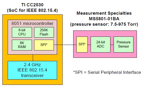
The block diagram shown in Fig. 2 shows a wireless sensor node in the WSN for a freeze dryer. As shown in Fig. 2, a system-on-chip (SoC) supporting ZigBee is chosen to implement the WSN for a freeze-drying application.
The SoC, CC2530 manufactured by Texas Instruments (TI, Dallas, TX, USA), includes an 8051 microcontroller (8-bit CPU, flash memory, RAM, and peripheral interfaces) and a ZigBee transceiver. As the pressure and temperature sensor, an altimeter module, MS5801-01BA manufactured by Measurement Specialties Inc. (Hampton, VA, USA), is chosen. The altimeter module supports two different serial data links between the altimeter module and the microcontroller in the SoC. One is the serial peripheral interface (SPI) protocol, and the other is the inter-integrated circuit (I2C) protocol. In this work, the SPI protocol is chosen due to the fact that this protocol supports full-duplex communication with a higher throughput than I2C. Besides, the SPI protocol is not limited to 8-bit words, so messages of any size can be sent.
In order to supply stable direct current (DC) power to the altimeter module, a 3.3-V voltage regulator, TPS7A4533 manufactured by TI, is used. At the input port of the voltage regulator, a 9-V battery is connected to supply the DC power. The major components and their manufacturers are listed in Table 1.
[Table 1.] Major components and their manufacturers
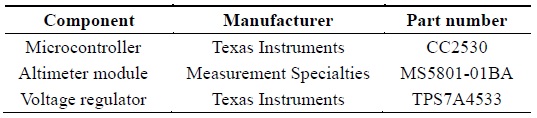
Major components and their manufacturers
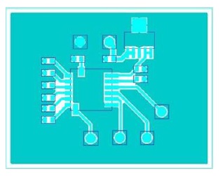
Since the altimeter module and the voltage regulator need to be integrated on a printed circuit board (PCB), a simple PCB artwork has been created using CADSTAR, automated PCB design software manufactured by Zuken, Inc. A schematic to fabricate a PCB, called a sensor board, for the altimeter module and the voltage regulator is shown in Fig. 3. By using CADSTAR, we can easily convert this schematic into a Gerber file, a well-known PCB image format. The Gerber image of the schematic shown in Fig. 3 is shown in Fig. 4. The PCB made of a Rogers RT/duroid 6006 substrate is fabricated using an LPKF C100HF circuit board plotter.
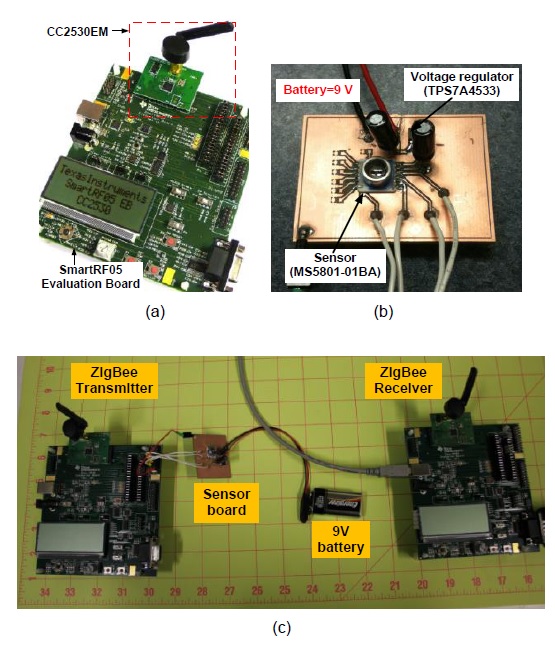
The photographs of the implemented WSN for a freeze dryer are shown in Fig. 5. As shown in Fig. 5(a), the TI CC2530 (ZigBee SoC) evaluation board and development kit is used to reduce the PCB design time for the SoC. The PCB on which the altimeter module and the voltage regulator are integrated is shown in Fig. 5(b). The dimensions of the sensor board are 45 mm × 35 mm. The bypass capacitors at the input and the output port of the voltage regulator shown in Fig. 3 are illustrated in Fig. 5(b). As can be seen in Fig. 5(c), the sensor board is connected to a ZigBee transmitter through the SPI protocol. As mentioned previously, the sensor board is powered by a 9-V battery. The ZigBee receiver is connected to a data acquisition computer (not shown in Fig. 5) through the RS-232 serial port on the CC2530 evaluation board by using a serial-to-USB converter.
The installation and operation of the WSN shown in Fig. 5 in a freeze dryer will be discussed in the next section.
Two separate software modules, a transmitter and a receiver, were implemented in one executable. One must select the roles of the boards from the application menu. One board must be operated as the transmitter, and the other as the receiver. Then, a one-way radio-frequency (RF) link between the transmitter and the receiver will be established when the two modules are successfully initiated.
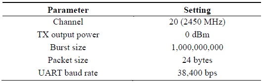
The sensor board is connected to the ZigBee transmitter (see Fig. 5). The transmitter must be configured to send packets by setting the channel, the output power level, the burst size, and the packet size. A packet includes 8-byte pressure value, 8-byte temperature value, 4-byte sequence number and 4-byte padding value between sequence number and pressure value. Therefore, the packet size is 24 bytes. The details of the parameter settings are presented in Table 2. The liquid crystal display (LCD) on the transmitter displays the measured temperature and pressure inside the freeze dryer as well as the number of transmitted bytes.

Parameter settings
The receiver displays the current temperature and pressure as well as the number of received packet. In order to send sensor data to a personal computer (PC), a universal asynchronous receiver/transmitter (UART) serial port is set at the receiver. The received data will be saved and managed by the data acquisition computer that is connected to the receiver via a serial communication cable. A baud rate of 38,400 is used in the receiver.
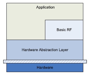
The transmitter and the receiver are implemented as applications on top of TI’s layered software architecture shown in Fig. 6.
Basic RF offers a protocol for transmission and reception by using a two-way RF link. The protocol uses a subset of IEEE 802.15.15 MAC-compliant data and acknowledgement packets to create a simple but secure data link layer for wireless communication.
The altimeter module is connected to the transmitter board. To use the sensor in the transmitter application, an SPI module is implemented in the hardware abstract layer (HAL) to communicate with the altimeter module. The transmitter, an SPI master, sends the analog/digital conversion (ADC) command to the sensor when it needs to read the altimeter module data. Then, the altimeter module, an SPI slave, sends back the current altimeter module readings to the master.
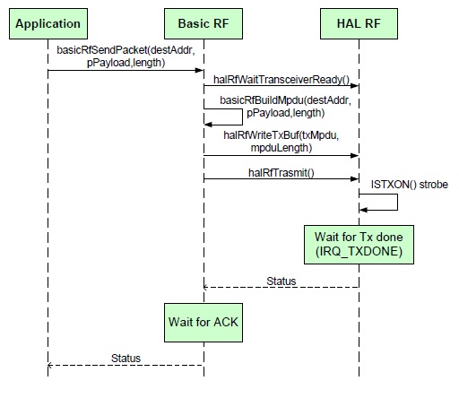
Fig. 7 shows the sequence of function calls in the transmitter using Basic RF. See [6] for more details on function calls. The application prepares the payload to send and sends it by calling basicRfSend(). Then, Basic RF waits until the transceiver gets ready by calling halRfWait TransceiverReady(). After transmitting data, Basic RF waits until the transmission is completed. The ACK status will return to the transmitter before a predetermined time if everything goes well.
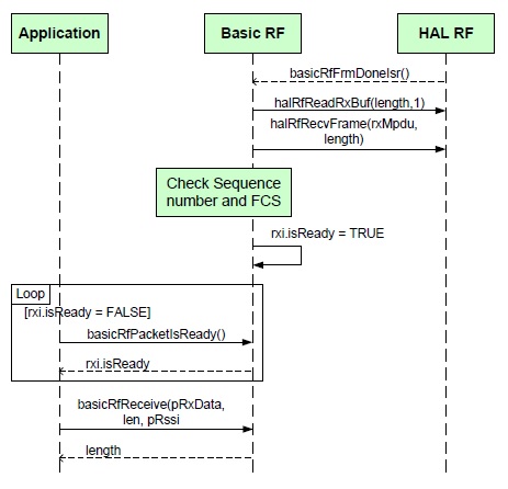
In the receiver, the sequence of function calls occurs as shown in Fig. 8. The actual packet transmission is done by an interrupt handler in Basic RF. As soon as a complete packet is received thanks to the interrupt handler, Basic RF can set a ready flag. Then, the receiver application can notice that an RF packet is ready by checking the flag in a loop to check whether the packet is ready or not. When the ready flag is set, the receiver reads out the transmitted data by calling basicRfReceive().
>
A. Installation of Wireless Sensor Network in Freeze Dryer
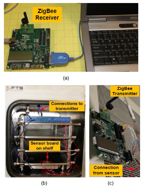
In order to demonstrate the functionality and efficiency of the developed WSN, it is installed in a laboratory freeze dryer called LyoStar and manufactured by FTS Systems. The ZigBee receiver, shown in Fig. 9(a), is connected to a data acquisition computer to record the pressure and temperature profile in the freeze dryer with respect to time. As shown in Fig. 5(c), the ZigBee transmitter with the sensor board is too bulky to install in the freeze dryer. Since the bulky transmitter with the sensor board may disturb the air flow in the freeze dryer, only the sensor board is placed on a shelf in the freeze dryer, as shown in Fig. 9(b). Instead of placing the ZigBee transmitter inside the freeze dryer, it is placed on the wall of the freeze dryer, as shown in Fig. 9(c). The ZigBee transmitter and the sensor board are connected through the thermocouple jacks in the freeze dryer.
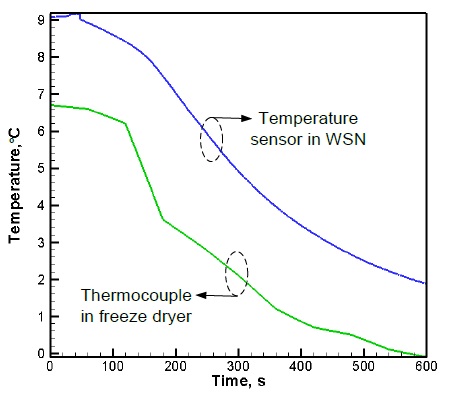
First, the temperature profile measured by the WSN is compared with the temperature profile measured by the thermocouple preinstalled by the manufacturer in the freeze dryer. As can be seen in Fig. 10, there is a temperature difference of 2℃ between the measurements of the temperature sensor in the WSN and those of the thermocouple. This difference might be attributed to the different measuring locations in the freeze dryer. The preinstalled thermocouple was attached to the shelf by a plastic tape, but the sensor board was just placed on the shelf. Nonetheless, the temperature profile shown in Fig. 10 indicates that both methods exhibit a very similar temperature variation over time. In fact, the temperature profile measured by the WSN is smoother than that measured by the thermocouple. Since the temperature measured by the WSN was updated every 100 ms, the temperature profile shown in Fig. 10 is a very smooth curve. This implies that the WSN can measure and monitor the temperature in the freeze dryer more accurately and efficiently than the thermocouple. Since the temperature measured by the thermocouple was measured at a discrete time interval, the temperature profile is rough. Due to the discrete time interval, the temperature variation within a short period of time may be lost. It is a very crucial function for a freeze dryer to monitor temperature continuously, particularly in the case of very low temperatures. The proposed WSN can perform this crucial function accurately and efficiently.
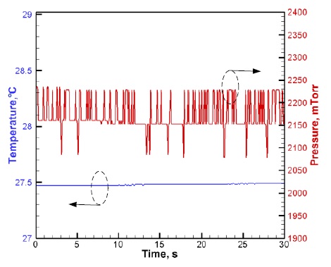
Secondly, the temperature and the pressure in the freeze dryer are measured simultaneously by the WSN. The temperature and the pressure in the freeze dryer are fixed by the preset function of the freeze dryer at 27℃ and 2000 mTorr, respectively. Since the lowest limit of the pressure sensor is 7500 mTorr, as stated in the manufacturer’s specifications, we conducted an experiment to measure the lowest limit of the pressure sensor in the altimeter module. Further, as can be seen in Fig. 11, there is a difference of only 0.48℃ between the preset temperature and the measured temperature. In the pressure measurement, a maximum difference of 230 mTorr (=0.3 mbar) is observed. The fluctuation in pressure is due to the fine resolution of the pressure graduations in the graph.
On the basis of Figs. 10 and 11, the functionality and efficiency of the WSN are verified with its excellent performance for freeze dryer applications.
By using an SoC that includes a microcontroller and a ZigBee transceiver, and an altimeter module that includes a pressure and temperature sensor, we designed and implemented a WSN for freeze dryer applications. A comparison with the temperature profile measured over time in a freeze dryer by a thermocouple revealed that the temperature profile measured by the WSN was considerably smoother. Further, the temperature and pressure measurements in the freeze dryer revealed that there was a difference of only 0.48℃ and 230 mTorr between the preset values and the measured values, respectively. Therefore, we concluded that the proposed WSN for freeze dryer applications could improve the capability of monitoring and controlling environmental factors, namely temperature and pressure, in freeze dryers.


![Software architecture [6]. The transmitter and the receiver were implemented on the ‘Application’ layer of the layered architecture provided by Texas Instruments.](http://oak.go.kr/repository/journal/17023/E1ICAW_2015_v13n1_21_f006.jpg)
![The sequence of function calls in the transmitter module [6].](http://oak.go.kr/repository/journal/17023/E1ICAW_2015_v13n1_21_f007.jpg)
![The sequence of function calls in the receiver module [6].](http://oak.go.kr/repository/journal/17023/E1ICAW_2015_v13n1_21_f008.jpg)