Recently, transmission of radio frequency (RF) signals over free space optical (FSO) link, which is also referred to as radio over FSO, has gained a lot of research attention. It has been proposed as one of the solutions for last-mail applications [1, 2]. Compared with the RF system, FSO is less affected by snow and rain, but can be severely affected by atmospheric turbulence and fog. RoFSO communication systems can transfer radio signals with high transmission capacity, unlicensed spectrum, ease of deployment, low cost and high security [3]. However, the performance of RoFSO can be degraded by various atmospheric conditions such as fog, snow, smoke, and turbulence, which result in attenuation and intensity fluctuation of the laser beam at the receiver side. Experimental results showed that dense fog can cause an extinction coefficient of up to 270 dB/km [4]. Additionally, the optical power attenuation due to thick fog, snow and haze is wavelength independent [5]. To achieve the over 99.9% availability requirements of the telecom industry in a dense foggy environment, the FSO link is limited to about 500 m, where sufficient link margin is available [6]. For longer transmission link range under dense fog, a complementary RF link at lower data rate can be used to back up the FSO link.
In clear atmosphere with a typical attenuation coefficient of 0.43 dB/km, an FSO link of over 1 km is achievable. However, the major challenge for FSO in clear atmosphere is the turbulence induced irradiance fluctuation, especially for the link range beyond 1 km [7]. The irradiance fluctuation, also referred as scintillation, is caused by the inhomogeneities in the temperature and pressure of the atmosphere along the propagation path, which causes random variations of refractive-index [8]. Scintillation could result in deep signal fades that lasts for ~ 1-100 µs [9]. For example, a link operating at 1 Gbps could result in a loss of up to 105 consecutive bits. To fully understand and predict FSO performance, a number of models have been developed to describe the statistical distribution of atmospheric turbulence. The most widely reported is the lognormal channel model, which is mathematically convenient and tractable [7]. For longer link range where multiple scatterings exist, the incident wave becomes increasingly incoherent and the lognormal model becomes invalid. The GG turbulence model is based on the assumption that the irradiance fluctuation of a light beam propagating through the turbulent atmosphere consists of small scale (scattering) and large scale (refraction) effects [7]. The GG statistic distribution of irradiance fluctuation is valid for all turbulence scenarios from weak to strong.
To mitigate the weather effects, a number of schemes have been proposed, such as coding techniques [10, 11], adaptive techniques [12-14] and space diversity techniques [8, 15, 16]. Additionally, multihop FSO systems employing both amplify-and-forward (AF) and decode-and-forward (DF) relaying schemes have been studied [17]. Unlike in RF communications, the small-scale fading statistics of FSO communications are distance dependent. Therefore, the multihop technique not only improves the path-loss compared to direct transmission, but also mitigates the small-scale fading statistics [18]. Most of the existing work reported multihop FSO systems employing electrical amplification, where the received optical signal at each relay was converted into an electrical signal by a photo-detector, amplified and then converted back into an optical signal by a laser [17, 19]. In [17], the outage probability of multihop FSO link using AF and DF relaying was investigated in lognormal fading, where the noise at the relays and the destination is dominated by the shot noise modeled as an additive white Gaussian noise (AWGN) model. The closed-form expressions for the outage probability and the average BER of binary modulation schemes for multihop FSO employing AF relaying under a GG turbulence channel have been presented [19].
The main objective of this paper is to use all-optical AF relays employing erbium-doped fiber amplifiers (EDFAs) for amplification, which avoids the complexities associated with optical-to-electrical (OE) and electrical-to-optical (EO) conversion. EDFAs are a mature technology, which has a wide-spread use in optical fiber communications as a preamplifier or an in-line amplifier in the 1550 nm range [18]. The application of EDFAs in FSO AF relays has been recently proposed in [20-22]. However, results in [22] only included the amplified spontaneous emission (ASE) noise and shot noise caused by background radiation without considering the weather conditions in the FSO system. In this paper, we consider an all-optical multihop RoFSO communication system with AF relays, particularly the CSI technique. The lower bounds for BER and outage probability have been derived considering the ASE noise and the background noise at each set of relays under different channel conditions. The proposed channel model takes into account the propagation loss, atmospheric attenuation and turbulence induced fading. The GG statistic distribution has been used to describe the atmospheric turbulence.
The rest of this paper is organized as follows. In Section Ⅱ, the all-optical multihop RoFSO communication system is introduced. The end-to-end SNR and lower bound expressions for BER and outage probability of the multihop FSO system are derived in Section III. Results discussions are presented in Section IV. Finally, some conclusions are given in Section V.
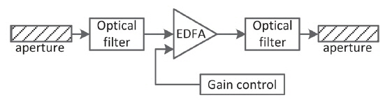
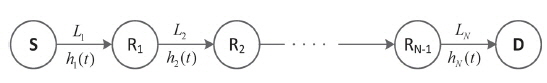
We consider an all-optical multihop RoFSO communication system employing the IM/DD, as shown in Fig. 1 [17]. The source node S transmits the optical signal modulated by RF signals to the destination node D via
In this work, we assume the source node S transmits the optical signal modulated by

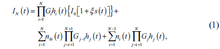
where
where

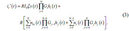
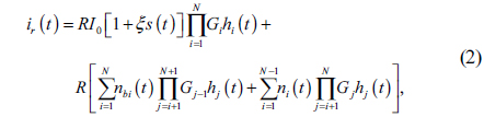
In Eq. (3), the first term is the signal transmitted by source node S, the second term is the background noise received by the receiver apertures and the ASE noise produced by the relays.
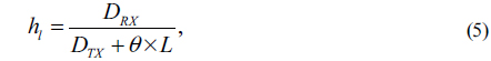
The channel gain

where

where

where
where
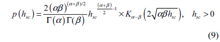
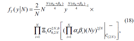
The fading

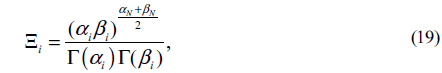
where Γ(⋅) is the Gamma function,
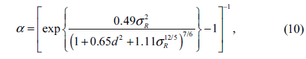
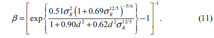
Here, where
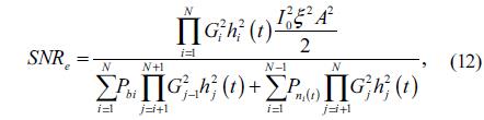
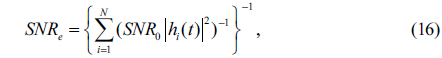
The BPSK modulation scheme will be considered in this paper. The BPSK signal can be transferred without changing its format by the RoFSO system, which avoids the adaptive threshold required by the OOK-modulated FSO systems [23]. The end-to-end electrical SNR before the RF demodulator according Eq. (3) can be expressed as:

where

where
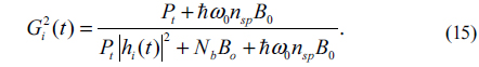
Assuming the maximum output power

where

As the CSI changes slowly compared to the transmitted RF signal, the amplification gain is slowly variable.
In a practical FSO system, the power density of the background radiation can be
where represents the SNR in the ideal channel when no atmospheric fading and attenuation exist.
3.2. BER Performance and Outage Probability
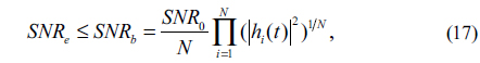
In this section, we derive the lower bound expression for BER and outage probability of the all-optical multihop RoFSO communication system. Since the PDF of the end-to-end SNR expression given by Eq. (16) is difficult to derive, the upper bound for Eq. (16) can be derived using the similar approach as in [19]. Using the inequality

where the equality holds when
where

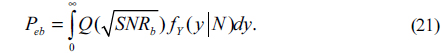
From Eq. (17), the lower bound for BER of the all-optical multihop RoFSO communication system using BPSK signaling format can be given by

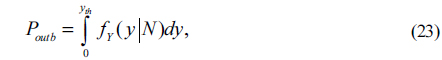
The outage probability is another important metric to evaluate the performance of multihop FSO system in fading channels. The instantaneous BER will significantly rise at a certain moment because of the deep fading for a communication system with an adequate average BER. The outage probability is defined as the probability that the instantaneous SNR of the system falls below the threshold SNR. The outage probability is defined as [25]:

where SNR

where
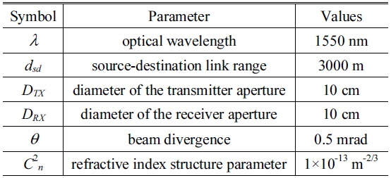
In this section, we present the simulation results for the BER performance and outage probability of the all-optical multihop RoFSO communication system in GG fading channel. The results are obtained via Monte Carlo simulations based on Eq. (16). The lower bound curves for BER and outage probability are plotted based on Eq. (21) and Eq. (23). In this paper, we assume the multihop AF RoFSO system with

System parameters
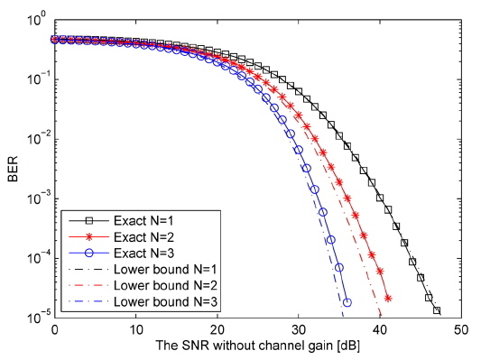
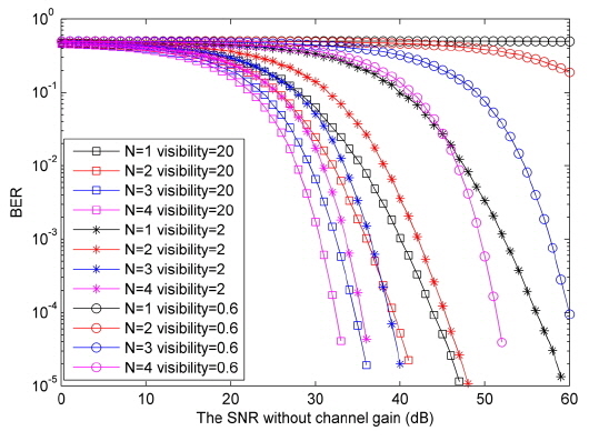
In Fig. 5 the exact end-to-end BER is plotted against
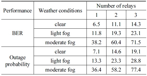
[Table 2.] Improvements (dB) at BER and outage probability of 10?5

Improvements (dB) at BER and outage probability of 10?5
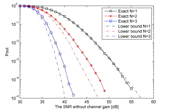
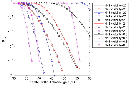
The exact end-to-end outage probability of the all-optical multihop RoFSO system is plotted against
In this paper, we have studied the performances of the all-optical multihop RoFSO system using AF relays. Both the BER performance and outage probability have been analyzed using different numbers of relays under various weather conditions. The proposed system employs the all-optical AF relays which eliminate the OE/EO conversions and have a variable gain with the full-CSI. Results demonstrate the performance of the proposed system will be improved by using additional relays. The BER performance improves ~6.5 dB, ~11.1 dB and ~14.3 dB for