The formulation of the holographic principle by Dennis Gabor in 1948 [1], and the invention of lasers a decade later, laid the foundations of holographic technology. The introduction of carrier frequency in holographic recording by Leith and Upatnieks in 1962 [2], and the publication by Denisuyk [3] in the same year on recording white-light-viewable reflection holograms, pushed forward optical metrology and display holography of three-dimensional (3D) still images. Advances in computers and optoelectronics enabled the development of holographic imaging technologies, such as holographic video [4] and holographic printing [5]. The current status of research on dynamic holographic display indicates that this technology still has a long way to go before the release of a commercial product. By comparison, the technology for holographic printing of 3D still images is the one closest to commercialization. Holographic stereogram printers, also known as direct-write digital holographic printers, have been developed and released as commercial products by Geola, Ultimate, and Zebra [6]. These printers rely on a holographic stereogram method, which records parallaxrelated images displayed on a spatial light modulator (SLM) onto a holographic emulsion as a volume reflection hologram [6-8]. The input data formed from incoherently acquired perspective images of the 3D scene carry only directional information, and thus this printing method inevitably suffers from longitudinal distortion in the reconstruction of deep scenes. In contrast, the recently proposed holographic fringe and wavefront printers use as input data for the SLM a computer generated hologram (CGH) [9-14], which encodes both directional and depth information. In the fringe printer the CGH is directly transferred onto the holographic emulsion, without a reference beam during recording [9]. The output is a thin transmission hologram that lacks color selectivity. The output of the wavefront printer, on the other hand, is a volume reflection hologram. This method relies on extraction of the wavefront coming from the 3D object, and thus resembles an analog holography recording process [10-14]. The main advantage of this method is distortion-free color reconstruction of target objects from the printed hologram, but it requires a 3D object model and a vast amount of calculations to generate the fringe pattern. The latter problem has been actively addressed lately by elaborating approaches for fast generation of CGHs. In addition, as the performance of multicore CPUs and GPUs improves, the problem of accelerated CGH computation can be solved.
Whilst commercialization of holographic printers and the wavefront printer in particular is forging ahead, a lot of problems should still be solved to elicit a positive public response. Shortcomings such as the small viewing angle provided by the printed hologram, unfavorable lighting conditions, and degradation of image quality when printing in color, presently prevent holographic printers from satisfying the demands of the market. A wider viewing angle could be obtained by improving the optical performance of the holographic printer. The fundamental requirement of holographic technology for coherent illumination renders impossible the use of regular lighting, such as fluorescent light or distributed light sources, and specialized lighting solutions should be developed. Research has been performed on the reproducibility of colors in color printing, but not much has been done on finding methods to improve image quality in the process of color production [15-17].
One prospective approach is mosaic recording [17], with spatial division of exposures in primary colors. It can be applied to both holographic stereogram and wavefront printing, due to spatial multiplexing of the printed hologram via sequential exposure of a large number of elemental holograms. In mosaic recording a single elemental hologram carries only one of the primary colors, and hence a crucial issue is to guarantee its small size. This type of recording corresponds to single-exposure recording, and produces bright reconstruction in saturated colors; however, it is vulnerable to the occurrence of artifacts superimposed on the reconstructed image that lead to quality degradation.
The aim of this paper is to propose a method to reduce image-quality degradation in a color wavefront printer with spatial division of exposures in primary colors. Image-quality improvement relies on the wavefront printing principle, which allows for rearrangement of input information. The paper is structured as follows: In Sec. 2 we briefly explain the principle of wavefront printing by presenting the optical design of our printing system, and describe the situation in which recording of a color mosaic worsens image quality. In Sec. 3 we show how to determine the color content to be encoded in a current CGH, and present the method for accelerated CGH computation that is used in the paper. In Sec. 4 we propose our method for improving color reproduction, by adaptive spatial partitioning of the SLM and controlling the exposure times at delivery of primary colors to the holographic emulsion. Experimental verification of the method is given in the final Sec. 5.
II. COLOR DEGRADATION IN MOSAIC RECORDING
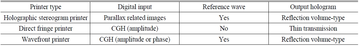
Holographic printers print holograms from digital contents onto a holographic plate. The printer input is a two-dimensional (2D) array of elemental digital patterns that encode the light field coming from the 3D object to multiple viewpoints. Accordingly, the printer output is an analog hologram composed of a large number of individually recorded elemental holograms. The digital contents to be recorded in an elemental hologram are displayed on an SLM as a 2D array of real numbers. The light diffracted from the SLM is optically processed and directed to the holographic plate. The output hologram is recorded successively by updating the information on the SLM and shifting the holographic plate with an X-Y stage. The digital input and types of recording for existing holographic printers are given in Table 1. As can be seen, the holographic stereogram printer and the wavefront printer with amplitude-type CGH easily support color printing of white-light-viewable holograms.
[TABLE 1.] Types of holographic printers

Types of holographic printers
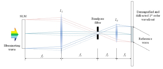
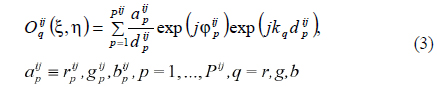
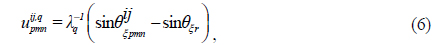
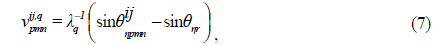
In the wavefront printer that we recently proposed [12], the light wavefront to be recorded is extracted from an amplitude-type CGH

where
In the optical design of our wavefront printer, the spatial filter is located at the rear focal plane of lens
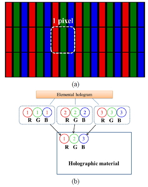
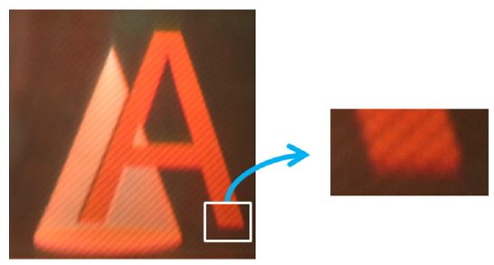
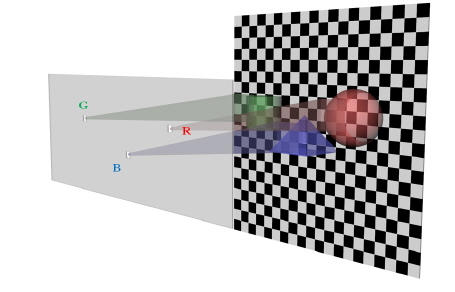
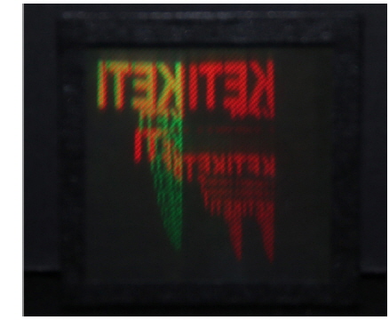
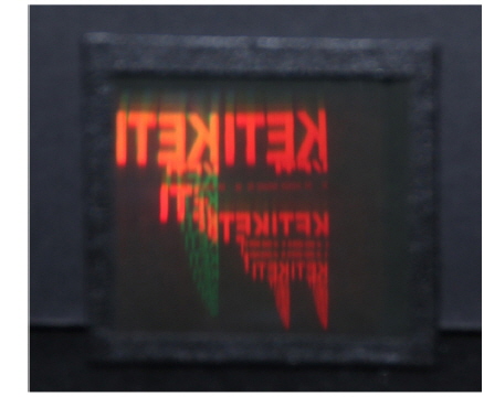
Basically, color production in a holographic printer is accomplished with a combination of red (R), green (G), and blue (B) lasers. A color hologram can be recorded by a multiple-exposure method that forms each elemental hologram as a combination of three color channels [6, 18]. The drawback of this approach is worsening of color reproduction, due to crosstalk between the RGB channels, and decrease in the light-sensitive material’s dynamic range attributed to each color. Thus the space-division exposure method is preferable for holographic printers. This method resembles the formation of color pixels in LCD displays, with one significant difference: A single pixel in an LCD display (Fig. 2(a)) carries three colors and has a size well below the threshold of human visual acuity. This plus a large number of pixels guarantee that the spatial separation of primary colors in an LCD display remains unnoticeable to the viewer. However, color production by mosaic delivery in a holographic printer receives one color per elemental hologram, as depicted in Fig. 2(b) [16]. If the color red is dominant in the content to be printed, the elemental holograms corresponding to the green and blue color channels are repeatedly printed as low-intensity patterns, and the color they reconstruct will be almost black. The color channels that are practically empty create a regular dark pattern, i.e. a stripe pattern is formed. Such a stripe pattern can be observed in Fig. 3, which shows reconstruction from a hologram printed with the wavefront printing system described in Sec. 5, using conventional mosaic recording. A similar pattern can be also found in Ref. [16]. Repetition of low-intensity recording has a damaging effect on the overall resolution, and becomes more pronounced if the size of the image decreases.
III. DETERMINATION OF THE COLOR CONTENT
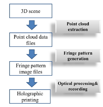
The degree of color degradation in mosaic recording depends on the color content to be encoded into elemental holograms. Spatial multiplexing applied in holographic printing closely resembles the ray-casting approach, which is now gaining popularity for CGH computation. A ray-casting algorithm divides the hologram plane into subholograms and casts rays from each subhologram onto the objects in the 3D scene [19, 20]. The objects are populated with primitives such as points or polygons, and appropriate methods (such as summation of spherical waves [19, 20] or angular spectrum propagation [21]) can be applied to describe the light wavefront coming from the primitives to the plane of the hologram. In this paper we adopt the ray-casting approach to generate the 3D content by using point-cloud object representation, in the scheme of Fig. 4. A set of point clouds was extracted for all elemental holograms, and fringe patterns were computed for each of them using the corresponding point clouds.Suppose that the hologram plane is divided into

The ray-casting approach is highly suitable for incorporating effects that create photorealistic imaging, such as viewpoint-dependent occlusion, shadowing, reflection, etc. Some of these effects are encoded in the phases ,
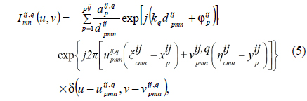
Calculation of

where is the distance between the point source at and the point on the CGH, are the amplitudes of the light field emanated by this source at the primary wavelengths


where is the holographic fringe pattern calculated at a primary color

where and are the incidence angles from the
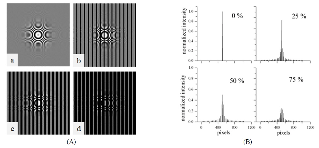
We conduct a numerical experiment, in which the object is a point at some distance from the hologram plane. The simulated hologram encodes the object beam as a fringe pattern, varying from 0 to 255 levels of intensity, for a reference wave that is normal to the plane of the hologram. The size of the hologram is 1024 × 1024 pixels, and the wavelength is 532 nm. To illustrate worsening of reconstruction when one or two color channels are practically empty, we convolute the hologram with a stripe pattern of zero intensity. We vary the width of the stripes to cover 25%, 50%, or 75% of the whole hologram. The obtained holograms are shown in Fig. 6. We also plot in Fig. 6 the cross sections of the reconstructions along a line passing through the point object and normal to the stripes. Degradation in the quality of reconstruction is clearly seen; as should be expected, it expresses itself as a strong decrease in intensity with occurrence of subsidiary peaks.
We also objectively assess the quality of images reconstructed from the holograms with stripes by using the peak signal-to-noise ratio (PSNR). This metric estimates globally the similarity between two images by calculating the PSNR as follows
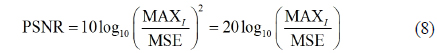
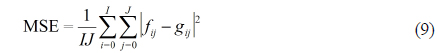
where MAXI is the dynamic range of the pixel values (255 for 8-bit grayscale images),
[TABLE 2.] PSNR of reconstructions from holograms with stripes
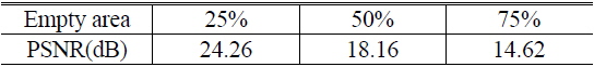
PSNR of reconstructions from holograms with stripes
The numbers in the “empty area” row give the percentage of the region with zero intensity in the fringe pattern. As can be seen from Table 2, the PSNR value is low even at an empty area of 25%, and further decreases with its increase in the fringe pattern. Obviously, high quality of the reconstructed image can be achieved by reducing the empty area in the fringe pattern.
IV. QUALITY ENHANCEMENT BY ADAPTIVE SLM PARTITIONING
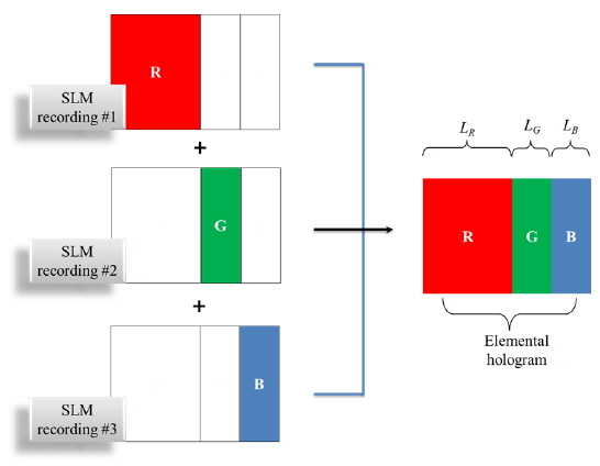
The method we propose for improving color reproduction of a wavefront printer is based on the holographic principle itself. Contrary to the existing mosaic printing, in which each elemental hologram gets a single color, we propose applying the space-division exposure method to the elemental holograms themselves by dividing the SLM area into three subareas to print the RGB colors. In addition, instead of fixing the RGB subareas to be equal to 1/3 of the SLM each, we propose to adapt their sizes
Consider a simplified example of a point cloud consisting of 16 red points, 4 green points, and 1 blue point. Obviously the blue channel gives a minor contribution to image quality when playing back the hologram, compared to the red and green channels. The impact of the red channel is the most pronounced. Based on this consideration, a gain in image quality can be achieved if a color channel with higher impact gets more pixels in the SLM, or more space on the holographic plate, than a channel with lower impact. This idea is elucidated in Fig. 7. The ratio between the RGB subareas is adjusted according to their contribution in the overall color content:

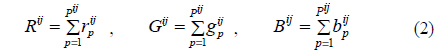
The proposed subdivision is easily implemented by feeding the input data only to the SLM subarea that corresponds to the primary color to be printed. By adapting the recording geometry to the color content, the damage caused by low-intensity or empty color channels is minimized, and undesirable artifacts can be avoided. However, adaptive subdivision of the elemental hologram inevitably changes the color expression. Actually, to maintain the color balance given by Eq. (2) in the representation of the 3D object, the hologram should exhibit the ability to reflect the primary colors equally.
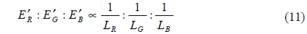
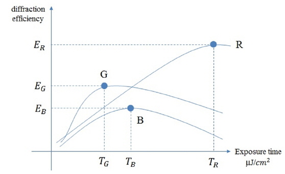
Assume that a white-light source such as D65 is used to reconstruct the printed hologram, and that the ratio between the RGB intensities it provides is 1 : 1 : 1. (Technically speaking, this ratio for the D65 source is not 1 : 1 : 1, and perception of colors depends on the sensitivity of the human eye, but further analysis will be postponed for future study.) Then, if the primary colors are recorded as patches of the same size on the holographic emulsion, equal brightness in a reconstruction of RGB colors at a given intensity is achieved by equalizing the diffraction efficiencies for the three wavelengths used in recording. This prevents a particular color from being brighter than the others when playing back the hologram. In general, panchromatic light-sensitive materials exhibit different diffraction efficiencies at the different RGB wavelengths [6]. For better comprehension, Fig. 8 gives a schematic representation of the exposure characteristics for the wavelengths of primary colors that might be observed for a typical light-sensitive material used for holographic printing. The exposure characteristic gives the diffraction efficiency as a function of exposure energy. The curves in Fig. 8 can be plotted also as a function of exposure time, provided the R, G, and B lasers deliver beams with equal intensities in the plane of the hologram. The exposure characteristics allow for determination of the maximum efficiency for each color. Because the maximum diffraction efficiencies

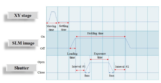
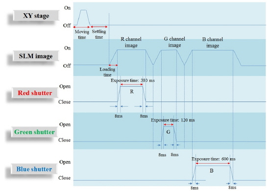
The change in diffraction efficiency can be achieved by varying the exposure time. In the existing mosaic exposure delivery, the optical header (Fig. 9) of the wavefront printer prints one elemental hologram at a time with one of the three RGB colors, and then moves to the next one. To print the RGB subareas into one elemental hologram, the fringe pattern displayed on the SLM is divided into subpatterns, corresponding to the RGB channels, that are printed with the optical header controlled as shown in Fig. 10. The exposure times are chosen with respect to the exposure characteristics of the used panchromatic holographic emulsion and Eq. (11). Thus, one needs to fulfill the following steps in recording each elemental hologram:
i) Evaluation of the color content for the point cloud corresponding to the elemental hologram, from Eq. (2); ii) adaptation of the subareas LR,, LG, LB on the SLM, according to Eq. (10); iii) adjustment of exposure times for the primary colors, from Eq. (11), and the exposure characteristics of the holographic emulsion iv) successive recordings at the wavelengths of the primary colors; and v) shift of the X-Y stage to the next elemental hologram.
While the second step in the procedure described above is implemented digitally, and for this reason is very precise, the third step relies on the measured exposure characteristics of the holographic emulsion used, and inevitably provides only approximate values for the RBG exposure times. Nevertheless, the improvement in color reproduction realized by combining numerical and analog estimates, as shown in the next Section, proves the feasibility of the proposed method.
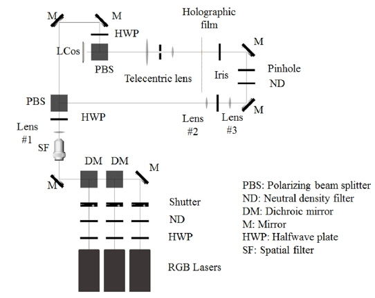
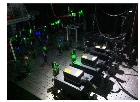
This study was conducted using the holographic wavefront printer shown in Fig. 11. A photograph of the experimental system is shown in Fig. 12. In the printer's optical system, three DPSS lasers with wavelengths of 473, 532, and 633 nm plus mechanical shutters were used for color production. A polarizing beam splitter (PBS) divided the laser beam in use into reference and object beams. The intensity ratio of the object and reference beams for each of the lasers was adjusted with a half wave plate (HWP). The CGHs to be recorded were displayed on an amplitudetype SLM. The light diffracted from the SLM was collected by the lens L1 of the telecentric lens system shown in Fig. 2; the spatial filter located at the rear focal plane of this lens cut off the undesired zeroth- and first-order diffracted beams. The -1st -order diffracted beam was demagnified by the lens
This paper presents a method to improve color reproduction in a wavefront printer using spatial division of exposures in primary colors. The wavefront printer records a volume reflection hologram as a 2D array of elemental holograms from CGHs displayed on an SLM. The wavefront coming from the object is extracted by filtering in the spatial-frequency domain. Mosaic delivery of exposures, in which an elemental hologram receives only a single color, avoids crosstalk between the color channels and provides bright reconstruction with saturated colors. It may, however, cause undesirable artifacts superimposed on the reconstructed image, if a color channel is empty or carries a very low-intensity fringe pattern. To solve this issue, we propose adaptive partitioning of the SLM according to the color content encoded in the input CGHs, and combined it with a controllable change of exposure times for the recording of primary colors, to maintain color balance when reconstructing the object. The CGH for a given elemental hologram is computed by ray-casting, which determines a set of primitives (points or polygons) to represent the 3D object. Replacing a single exposure of an elemental hologram with three exposures in primary colors increases only slightly the total printing time for printers with CW lasers, in view of the fact that the settling time of the X-Y stage is much longer than the exposure time. The method is verified using a color wavefront printer with demagnification of the object beam. The CGHs to be fed to the SLM were generated from a set of point clouds using a fast phase-added approach. The quality of reconstruction achieved with the proposed method demonstrates its efficiency in eliminating the stripe artifacts that are superimposed on reconstructed images in conventional mosaic recording.