Many applications require reliable and accurate images, especially in medical fields, where images play an increasingly important role in pathological diagnosis or surgical intervention. However, image quality is often affected by various artifacts such as noise, which can make it difficult to analyze, or to extract useful information. This can seriously affect the quality of pathological diagnosis. Therefore, denoising plays an important role in improving the quality of medical imaging. Basically, the goal of image denoising is to reduce the noise as much as possible, while retaining important features such as edges and fine details [1].
Computed tomography (CT) is one of the most important modalities in medical imaging. Unfortunately, the radiation exposure associated with CT is generally regarded as its main disadvantage. With respect to patients’ care, the least possible radiation dose is demanded. However, the dose has a direct impact on the image quality because of quantum statistics. Reducing the exposure increases the noise. The ratio of relevant tissue contrasts to the amplitude of noise must be sufficiently large for a reliable diagnosis. State of the art automatic exposure controls, which adapt the tube current according to the attenuation of the patient’s body, achieve a remarkable dose reduction [2]. Further reduction, however, increases the noise level in the reconstructed images, and leads to lower image quality [3]. Many different approaches for noise suppression in CT have been investigated. For example, iterative numerical reconstruction techniques optimize statistical objective functions to obtain better reconstruction at the cost of a higher computation time [4]. Other methods model the noise properties in the projections, and seek for a smoothed estimation of the noisy data, followed by filtered back-projection [5]. Furthermore, several linear or nonlinear filtering methods have been proposed for noise reduction in the sinogram or reconstructed images [6, 7]. In the majority of the sinogram-based methods, the filters are adapted in order to reduce the most noise in regions of highest attenuation. Thus, the main goal of these methods is the reduction of directed noise and streak artifacts. As a result, especially in the case of nearly constant noise variance over all of the projections, these filters either do not remove any noise, or the noise reduction is accompanied by noticeable loss of image resolution [3].
The goal of the new method described in this paper is the structure-preserving reduction of pixel noise in reconstructed CT images. An important requirement for any noise reduction in medical images is that all clinically relevant content must be preserved. In particular, edges and small structures should not be affected. Several edge-preserving approaches for noise reduction in images are known. The goal of all of these methods is to lower the noise power without smoothing across edges. Some popular examples are the bilateral filter (BF), and the guided filter. The key idea of the BF is that for a pixel to influence another pixel, it should not only occupy a nearby location, but also have a similar value. But the performances of these filters depend on the parameters, and it is difficult to obtain the optimal parameters [8]. The guided filter generates the filtering output, by considering the content of a guidance image. The guided filter can perform as an edge-preserving smoothing operator like a BF, but has better result near the edges. In addition, its output depends on the threshold value to differentiate between an edge and flat area [9]. Another approach is the nonlocal means (NLM) filter proposed by Buades et al. [10]. It takes advantage of the presence of repeating structures in a given image. Then, denoising is performed by computing a weighted average of pixels with similar neighborhoods. Since 2005, the NLM filter has been cited more than 500 times thanks to its efficiency and simplicity. Many extensions of this method to medical image denoising have later been introduced [11].
Recently, significant progress has been made in applying a neural network (NN) to signal processing. The neural filter (NF) is a type of nonlinear function approximator based on multilayer perceptrons. By training the NF with a set of input signals and desired signals, it acquires the function of a desired filter. Two classes of NFs have so far been proposed. One is realized as stack filters; an input signal is transformed into binary signals on the basis of the threshold decomposition; and then, each of them is input to each of the plural multilayer NNs. It has been shown in [12] that the performance of these NFs is excellent in removing impulsive noise from signals/images. The other is a filter where input signals are input directly to a multilayer NN. It has been shown in [13] that the performance of these NFs in removing Gaussian/quantum noise from signals/images is excellent. It has been reported that epsilon filters, which are nonlinear filters developed for noise removal, are special cases of the latter class of NFs [14]. Furthermore, it has been proved that any continuous mapping can be approximately realized by multilayer NNs [15].
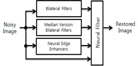
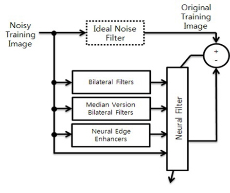
This paper proposes a NN based hybrid filter for removing quantum noise from CT images. The proposed filter consists of two types of BFs, a single or multiple Neural Edge Enhancer(s) (NEE), and a NF. The BFs can be treated as an example of input filters, which gives diverse local characteristics to be combined in NF according to the response of NEE. The NEE(s) can clearly enhance the desired edges (with different scales) from noisy images. The NF acts like a fusion operator, and attempts to construct an enhanced output image, by combining the information from several sources of input filters and NEE. The distinctive feature of the proposed filter over others is that it offers excellent edge and detail preservation performance, while effectively removing quantum noise. Image quality measurements, like the root mean square error (RMSE) and improvement in signal to noise ratio (ISNR) are used for performance evaluation, when there is a target image. Measurements like the mean to standard deviation ratio (MSR) and contrast to noise ratio (CNR) are used for performance evaluation, in the case of not having a target image. The modulation transfer function (MTF) is used as a means for determining how well the edge structure is preserved. Based on all these quality measures and means, the proposed filter shows better performance than the guided filter, and the NLM filter. In addition, there is no severe restriction to select the number of inputs for the fusion operator differently from the neuro-fuzzy system, and it is easy to train. Therefore, without concerning too much about the filter selection for fusion, one could apply the proposed hybrid filter to various images with different modalities, once the corresponding noise characteristics are explored.
The paper is organized as follows. In Section 2, the proposed hybrid filter is described, with its components of NF, BF, and NEE. The experimental results of the proposed NF are presented in Section 3, and compared with other filters, including the guided filter and NLM filters. Finally, Section 4 includes the summary.
In this section, the building blocks of our hybrid filter are briefly overviewed, and then the proposed hybrid filter is introduced.
2.1 Bilateral Filters and Quantum Noise
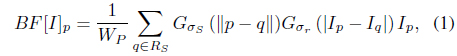
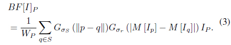
Blurring is perhaps the simplest way to smooth an image. The bilateral filter (BF) is defined as a weighted average of nearby pixels. The difference is that the BF takes into account the difference in value from the neighbors to preserve edges while smoothing. The BF is defined by

where the normalization factor
Quantum noise originates from a signal-dependent Poisson-distributed noise source. The Poisson-distributed noise can be approximated by a Gaussian, when the number of quanta is relatively large. So, we used signal-dependent Gaussian noise as a model of quantum noise. Assuming that the noise is quantum noise, a noisy image can be represented by

where
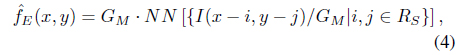
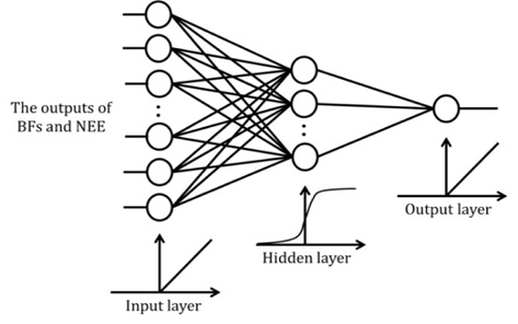
A NEE for clearly enhancing the desired edges from noisy images was proposed by Suzuki [17]. The NEE consists of a modified multilayer NN (The proposed NF has the same structure of NN as NEE shown in Figure 2.), which can directly handle input gray levels and output edge magnitudes. The inputs to the NEE are normalized pixel values which are spatially adjacent to a center pixel in

where
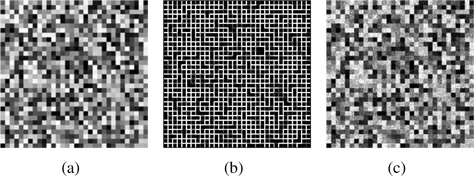
The NEE is trained by the modified back-propagation algorithm, which was derived for the above structure in the same way as in the derivation of the back-propagation algorithm [17]. For training, the input to NEE is prepared by the noisy version of the synthetic teaching image with quantum noises, and the target output of NEE is an ideal edge image. Figure 4(c), which is the corrupted version of synthetic image Figure 4(a) by quantum noise with
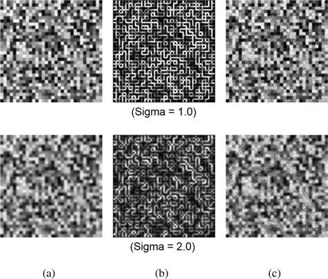
The edge strength in images depends on image scales: the strong edge in a large scale can survive even though large amount of smoothing has performed. In order to consider the strength of edges two additional NEEs are prepared for the hybrid filter. Figure 5 shows the Gaussian blurred images with different scale parameters, the edge responses after blurring and the nosy versions of blurred images with two different scales. NEE is trained to obtain the target edge response from the nosy version of blurred image.
2.3 Proposed Hybrid Filter Based on Neural Network
Figure 1 shows the structure of the proposed filter. The NF network utilizes the information from the two different versions of BFs (one is conventional BF in Eq. (1), and another is median version BF in Eq. (3)), the NEE(s), and the direct noisy input image to compute the output of the NF system, which gives the corresponding denoised image.
In order to get the optimal parameters of
{(
and
{(
respectively.
Note that there is no strict restriction to choose the types and the number of input filters connected to NF. One can choose any other type of filter(s) or the number of filters without too much consideration, differently from the hybrid filter based on neurofuzzy system [18]. In that rule-based hybrid filter, the number of rules could be exponentially increased as the number of input filters. Therefore, one should carefully select the necessary input filters to be connected with. In the proposed NF, there is no partition process of input space to establish the initial set of rules. The single or multiple NEE(s) are strongly recommended, however, because it behaves like a control input for NF to decide which inputs are chosen and how much influences of them are considered to combine according to the magnitude of local edges. Therefore, in the proposed hybrid filter, the results of 10 BFs and the direct noisy input are treated to provide a set of sufficient ensembles to be combined to produce the reasonable output under the control of the result of NEE(s).
2.4 Architecture and Training of Neural Filter
The architecture of the NF is shown in Figure 2, which is the same as the NEE [17]. The number of units in the input is equal to 12(or 14), which is the sum of the number of filters (5 conventional BFs and 5 median version BFs), the NEE(1 or 3), and one direct noisy input. The number of units in hidden layers is empirically set to 20 to prevent overfitting in the experiment.
The output of the NF is represented by

where x and y are the indices of spatial coordinates of image domain,
The proposed NN-based hybrid filter was applied to a number of medical CT images for performance evaluation, and compared with other filters. In order to evaluate the performance of the noise reduction methods, two aspects are mainly of interest; the noise reduction capability, and the preservation of anatomical structures. In order to quantify how much noise is suppressed, there are experiments in the two kinds of environments; in the cases of having target images, and not having them. The RMSE and ISNR are computed [19], when having target images. The ISNR is computed by
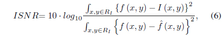
where
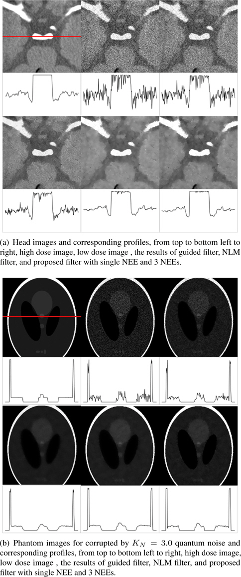
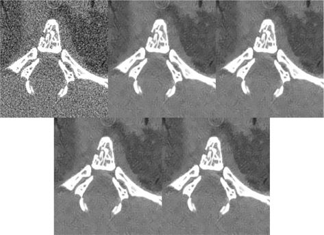
The input image is a low dose image, and the target image is taken as high dose image, to compute the RMSE and ISNR. Here, the low dose image was artificially synthesized from the high dose image, by adding quantum noise. The target brain image of the first row in Figure 6(a) acquired with MDCT of SIEMENS SOMATON Definition fresh, in which X-ray tube was operated with 120KVp, and 380mA of anodic current. The target phantom image in the second row, however, was obtained from a website. The output images of the proposed filter, guided filter and NLM filter are also shown in Figure 6, to enable the experimental outputs to be visually evaluated. In the images of Figure 6, some noises remained in the results of the guided filter. The noises are reduced effectively, in the outputs of the NLM filter and the proposed filter. The edges and details are the best, in the results of the proposed filters as shown in the profiles of head image. Table 1 shows the RMSE and ISNR values of the proposed filter and others. In the head images, the RMSE and ISNR of the proposed filters are better than those of the guided filter and NLM filter. However, the proposed filter and NLM filter have similar results for the phantom image. Additional NEEs gives the positive effects on the results except phantom images with respect to RMSE and ISNR. Also the profile shows the proposed filter with the additional NEEs for considering scale-dependent edges are better than the one with a single NEE. One can carefully conclude the more information to differentiate image regions the proposed NF performs the better, because the hybrid filter can have more control inputs to choose the outputs of various filtered results according to the region characteristics.
[Table 1.] RMSE and ISNR values for different filters, in KN = 3.0
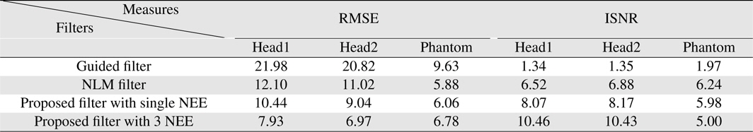
RMSE and ISNR values for different filters, in KN = 3.0
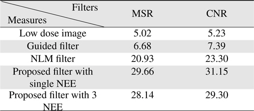
All these filters are applied to real, low dose images in the second experiment. The leftmost image in Figure 7 was captured by NFR Polaris G90 micro-CT system, in which X-ray tube was operated with 60KVp, 70

where
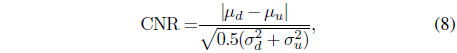
where
[Table 2.] MSR and CNR values for different filters and real, low dose image

MSR and CNR values for different filters and real, low dose image
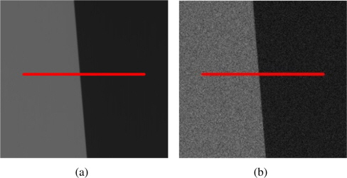
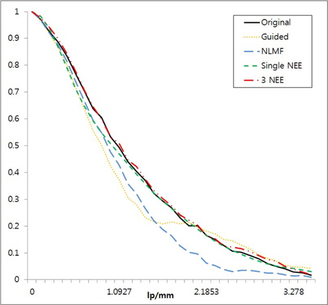
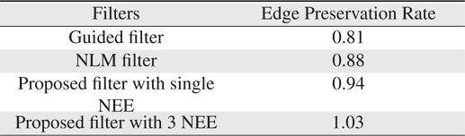
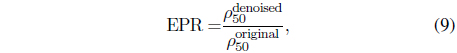
A measure for how well structure is preserved is obtained from MTF of a lie spread function (LSF). Here, the MTF was determined across an edge of the test image of Figure 8. In addition to a noise-free image in Figure 8 (a), the filtered results of its artificially corrupted version with quantum noise in Figure 8 (b) were prepared to measure the edge-preserving capability of various filters. In order to obtain the MTF, the line of the test image is considered across an edge marked by the red line in Figure 8. The edge profile was sampled along the line, and the corresponding LSF was obtained by taking a numerical derivative of the profile. The MTF is the normalized magnitude of Fourier transform of the LSF. The MTF results are shown in Figure 9, allowing a comparison of the proposed filter with the NLM filter and guided filter. The amount of deviations in the MTF from the original curve indicates the degree of smoothing of an edge in filtered images. As seen in Figure 9, the proposed filter leads to the best result, when compared to the guided, or NLM filters. The deviation from the original MTF to that of a filtered output can be approximately measured by the edge preservation rate(EPR) and listed in Table 3. The EPR can be defined by
[Table 3.] Approximate deviations from the original MTF

Approximate deviations from the original MTF
where and represent the spatial resolutions at which the half of normalized MTF is obtained from filtered and original images, respectively.
We propose a NN-based hybrid filter for removing quantum noise from medical CT images. The proposed filter is a hybrid filter that is obtained by appropriately combining two versions of BFs and a single or multiple NEEs. The training is easily accomplished by using simple artificial images that can be generated in a computer. After training, the NF network in the proposed filter acts like a fusion operator, and attempts to construct an enhanced output image, by combining the information from several sources. The most distinctive feature of the proposed filter over others is that it efficiently removes quantum noise from medical images, while successfully preserving edges and fine details in the original image. Based on several image quality measurements and means, the proposed filter shows better results than the others because the hybrid filter can have the control inputs from NEEs to choose the proper outputs of various filtered results according to the region characteristics. There is no severe restriction to select the number of inputs for the fusion operator differently from the neuro-fuzzy system. Therefore, without concerning too much about the filter selection for fusion, one could apply the proposed hybrid filter to various images with different modalities, once the corresponding noise characteristics are explored.