Microstrip antennas (MSAs) have attracted a great deal of attention in the past decade due to their planar structure, easy fabrication, and compatibility with integrated circuits. However, one of the main challenges in the practical MSA design process is surface wave excitation. On an MSA with a finite ground plane, surface waves propagate until they reach the edges where they are reflected back and diffracted. As a result, the back radiation of an MSA increases due to surface wave diffraction from the edges of the ground plane. This effect degrades the isolation between two antennas. Various structures, such as an electromagnetic band-gap [1], soft/hard surface [2,3], and partial substrate removal [4,5], have been proposed to reduce the surface waves in printed MSAs.
One simple method for reducing the back-lobe radiation of an MSA is using a partially removed rectangular ground plane of the antenna [6]. The effect of the partial ground plane removal reduces the back-lobe radiation of the MSA by suppressing the surface wave diffraction from the edges of the antenna ground plane. We present a new method for further reducing the back radiation of an MSA by loading split-ring resonators (SRRs) in a partially removed ground plane.
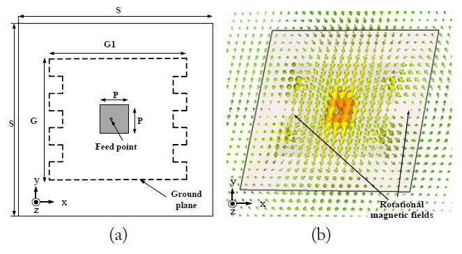
An MSA with a meandered ground plane of the E-plane direction that operates in the dominant mode (TM10) at 2.5 GHz is designed, as shown in Fig. 1(a). This MSA with a square patch element is designed on the Rogers R3210 substrate (having a relative dielectric constant of 10.2, a thickness of 1.27 mm).
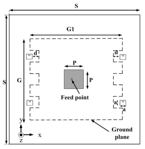
The optimized physical dimensions (in millimeters) of the MSAs are as follows: S = 120, G = 70, G1 = 86, and P = 18. The simulated magnetic field distributions within the substrate near the ground plane of the MSA are plotted in Fig. 1(b). The complex power density in the vicinity of the MSA on the conventional ground plane can be expressed as; . By using the meandered ground plane, the normal magnetic field component (Hz) is produced between the two meandered slots. It is observed that the magnetic field circulates between the two slots on the meandered ground plane of the MSA, and the magnetic field in the middle slot is near zero due to the symmetry of the induced currents along the y-axis in the ground plane edge of the MSA. To further reduce the ground-plane edge diffraction, which accounts for back radiation of the MSA, we prepared a SRR. By placing SRRs inside the slots of the meandered ground plane edge where the magnitudes of the magnetic field component (Hz) are strongly distributed, some parts of the diffracted power density can be reduced. Fig. 2 shows the geometry of the proposed MSA loaded with four SRRs in the slots of the meandered ground plane. The optimized physical dimensions (in millimeters) of the MSA and the SRR are as follows: S = 120, G = 70, G1 = 86, P = 18, a = 5.85, and d = 4.
The metal used for the metallic SRR patterns is copper with a conductivity σ = 5.8×10⁷ S/m. It was placed within a Rogers R3210 substrate, and computer simulations for the proposed MSA were carried out.
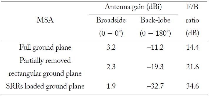
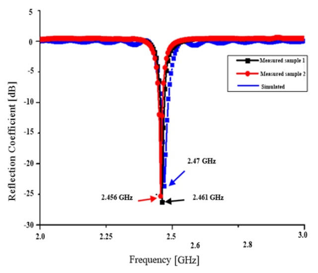
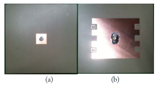
The simulated gains at the two different angles (θ = 0°, 180°) and the front-to-back (F/B) ratios of the MSAs are summarized in Table 1. Notably, the F/B ratio of the proposed MSA is improved. By removing some parts of the ground plane of the MSA, a slab-waveguide structure is formed near the end of the substrate edge. As a result, there are field minima at the ends of the removed ground plane [6]. In comparison with the conventional MSA having a full ground plane of the same size, the broadside gain (at θ = 0°) of the proposed MSA reduced by 1.3 dBi. This is attributed to the fact that a portion of the surface waves radiated from the ground plane edges contributes to space waves. However, the back-lobe gain (at θ = 180°) was improved by around 21.5 dBi. As a result, the F/B ratio increased from 14.4 to 34.6 dB due to the meandered ground plane and the use of the loading SRRs in the slots. In order to verify the simulations, a prototype MSA loaded with SRRs in the meandered ground plane was fabricated on a Rogers R3210 substrate; a 50-Ω SMA coaxial probe connecter was installed for feeding the MSA. A photograph of the fabricated antenna is shown in Fig. 3. Fig. 4 shows a comparison of the simulated and measured reflection coefficients of the proposed MSA.
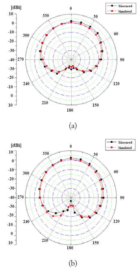
It can be noted that a slight reduction in the measured bandwidth (S11 < –10 dB) in comparison with that of the simulated result is attributed to the fabrication tolerances. The simulated resonant frequency of the MSA decreases from 2.47 to 2.46 GHz due to the loading effect of the SRRs. However, the measured and simulated resonant frequencies of the MSA agree well with each other. The measured radiation patterns at a frequency of 2.46 GHz are shown in Fig. 5. In both the E-plane and the H-plane, the MSA shows a smooth symmetric omni-directional pattern in the xy-plane with slight backward radiation.
The measured broadside (at θ = 0°) and back-lobe gains (at θ = 180°) are around 2.8 and –29.4 to –37.2 dBi, respectively. As a result, an F/B ratio of 32.2–40.0 dB was achieved experimentally.
The effect of the SRRs loading in the slots of meandered ground plane edges of an MSA were investigated experimentally. It has been shown to improve the F/B ratio of the MSA by at least 18 dB as compared with that of a conventional MSA having a full ground plane of the same size. The structure of the proposed MSA is very simple and can be implemented with ease. When this structure is used between two MSAs, a mutual coupling reduction effect can also be generated. This structure can be applied to reduce back radiation in the MSA antenna design.