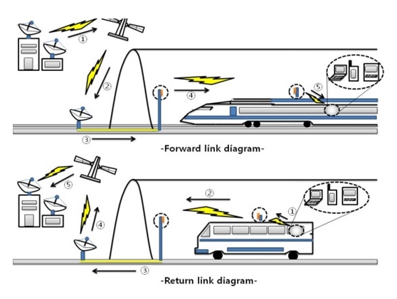
People want to use the internet service with no time and place restrictions. This demand has been met by the development of various wireless internet technologies, such as wireless local area network (WLAN), worldwide interoperability for microwave access (WIMAX), and wireless broadband (WIBRO). However, WIMAX and WIBRO services have limited use with high-speed moving objects [1], so an interworking WLAN and satellite system is currently being studied to resolve this problem. However service interruptions remain a problem when a high-speed moving object (bus, taxi, and train) passes through a shadowing region (for example, a tunnel). Continuous communication at the tunnel requires a gap filler system that interconnects the satellite and the wireless terminal, as shown in Fig. 1. When the electromagnetic wave is transmitted in the tunnel through a gap filler system, various propagation losses and multipath fading effects occur [2-4]. The gap filler system requires three small antennas: one outside the tunnel, one inside the tunnel, and one on the moving object. Satellite internet service consists of a forward link (bandwidth, 72 MHz) and return link (bandwidth, 36 MHz) and the gap filler system usually use dual-band (IEEE 802.11 a/b). Therefore, this system needs a small size and a high gain dual-band antenna or wide-band antenna [5]. We have been studying a dual-band antenna at the ISM bands (2.4 GHz band, IEEE 802.11b; 5.8 GHz band, IEEE 802.11a). The forward link consists of the following communications: from the earth station to the satellite, from the satellite to the gap filler, and from the gap filler to the potable terminal. The return link consists of the following communications: from the portable terminal to the gap filler, from the gap filler to the satellite, and from the satellite to the earth station. The system is shown in Fig. 1 [5].
In this paper, we have proposed a dual-band gap-filler antenna with a Phi-shaped slot on the circular patch. The proposed gap-filler antenna has high-gain, small-size, simple structure, and similar radiation patterns at the dual-bands. Details of the proposed design are described and experimental results of the fabricated antenna are presented. The measured gain is 9.07 dBi and 7.72 dBi at each band.
II. ANTENNA DESIGN AND SIMULATED/MEASURED RESULTS
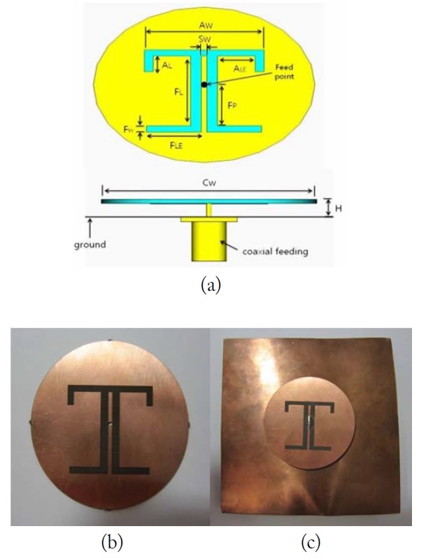
Fig. 2(a) shows the geometry of the proposed dual-band Phi-shaped slot gap filler antenna. The diameter of the circular patch on the substrate (Taconic TLX-9: ε
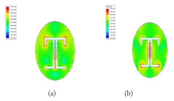
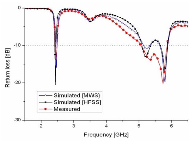
Fig. 3 shows the simulated and measured return losses of the proposed gap-filler antenna. The measured results agree well with the simulated results. The slight difference between the simulated and measured results seems to have arisen as an effect of soldering the feeding connector and the antenna during the fabrication. A return loss < -10 dB is associated with an impedance bandwidth for the proposed antenna of 2.39–2.51 GHz and 5.2–5.93 GHz. Fig. 4 shows the simulated current distribution at the frequency of 2.45 and 5.8 GHz, respectively. The resonance of the 2.4 GHz band occ-urs at the upper slot and the resonance of the 5.8 GHz band occurs at the lower slot. We also studied the effects of the stubs on the return loss. First, we examined the effect of the antenna geometry AL and FL on the return loss. The simulations showed that each band can be controlled by adjusting the length of AL and FL.
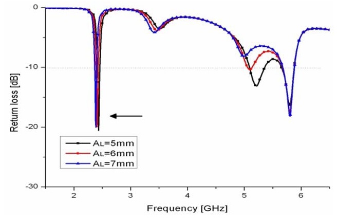
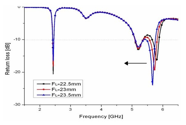
Fig. 5 shows the variation in the return loss versus frequency for different sizes of AL. As AL is increased, the 2.4 GHz (IEEE 802.11b) band is moved to the low frequency. The optimized value of AL in this design is 5 mm. Fig. 6 shows the variation in the return loss versus frequency for different sizes of FL. As FL is increased, the 5.8 GHz (IEEE 802.11a) band is moved to the low frequency.
The optimized value of FL in this design is 22.5 mm. Therefore, each band can be controlled by adjusting the length of AL and FL.
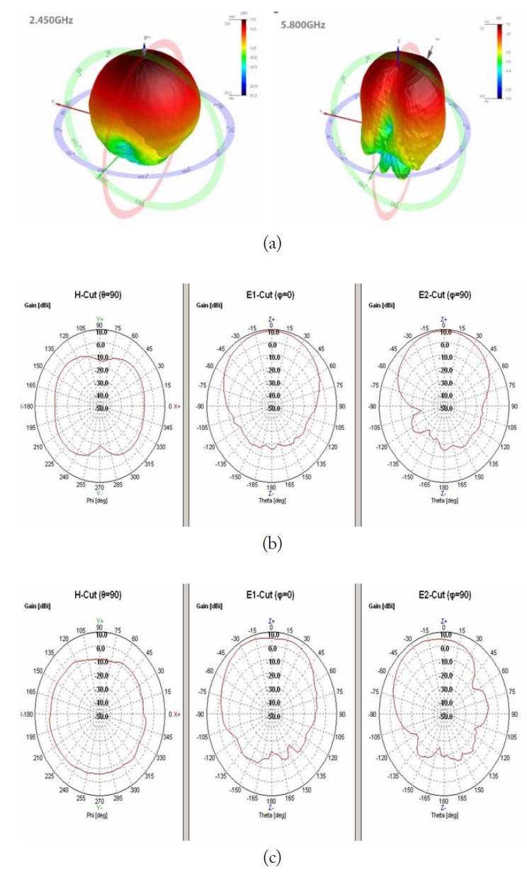
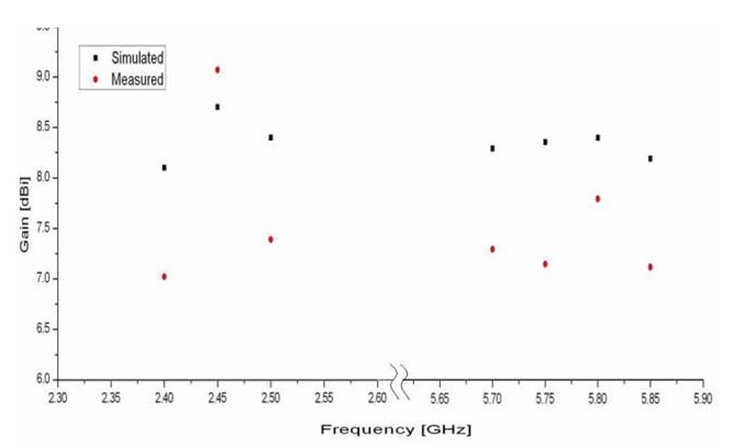
Fig. 7 shows the measured radiation patterns at 2.45 and 5.8 GHz. The proposed gap-filler antenna has a bore-sight radiation pattern of high gain. Fig. 8 shows the measured and simulated antenna gain of the proposed gap-filler antenna. The peak gain of the proposed gap-filler antenna is 9.07 dBi and 7.72 dBi at the center frequencies of 2.45 GHz and 5.8 GHz, respectively.
A new dual-band Phi-shaped gap filler antenna is proposed and we have fabricated and tested the proposed antenna. The proposed antenna has high-gain, small-size, simple structure, and good radiation patterns for the satellite internet service. Each band of the proposed antenna can be controlled by adjusting the length of AL and FL. The measured gain is 9.07 dBi and 7.72 dBi at each band. Thus, the proposed gap filler antenna is suitable for satellite in ternet service applications.

![The gap filler system for satellite internet service [5].](http://oak.go.kr/repository/journal/15727/E1ELAT_2015_v15n2_111_f001.jpg)