Outdoor insulating bodies have conventionally been made of glass and porcelain materials and, recently, epoxy insulating materials have been introduced to substitute for conventional ceramic materials because epoxy materials as insulators have several advantages such as light weight, good water repellance, and resistance to pollution compared with those glass and porcelain materials [1-3]. Especially, cycloaliphatic epoxy families have been used for outdoor applications because aliphatic cyclic structures are superior to aromatic bisphenol structures in the resistance to UV radiation, carbon formation, and surface discharges. The inherent low viscosity of these aliphatic cyclic epoxies enables them to be formulated with high levels of inorganic fillers [4]. Generally, 65~80 wt% of micro-sized silica is incorporated into the epoxy matrix to satisfy the dimensional stability of heavy electrical equipment.
Carboxylic acid anhydrides are commonly used hardeners for epoxy resins in these applications due to their longer working time, lower exothermic heat, lower processing viscosities, and moderate-to-high glass transition temperatures. To make the reaction activation energy lower, a tertiary amine is commonly used.
The performance of the epoxy/silica microcomposites is limited by high humidity levels and polluted environments because conductive pollutant layer leads to considerable reduction in insulation performances, such as surface leakage current, arcing, and flashover. The effect of humidity and pollutants can be addressed by reducing the wettability of the surface or increasing the repellency to moisture and humidity by imparting hydrophobicity. To increase hydrophobicity, water repellents, such as silicone oils, can be introduced into the epoxy system [5,6].
Carboxylic acid anhydrides are commonly used hardeners for the epoxy resins in these applications due to their long working times, lower exothermic heat, lower processing viscosities, and moderate-to-high glass transition temperatures. To make the reaction activation energy lower, a tertiary amine is commonly used. To modify the interface between the epoxy matrix and the inorganic filler, the surface of the filler is treated with silane coupling agents, such as epoxy-type, amine-type, and hydroxy-type coupling agents.
In this study, electrical and mechanical properties of epoxy/silica composites were studied by testing specimens prepared through mixing a micro-sized silica treated with an epoxy-type silane coupling agent with a cycloaliphatic epoxy resin to apply the microcomposite to an outdoor electrical insulator. The effect of microsilica content on the properties was studied.
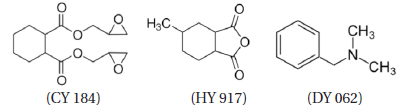
An cycloaliphatic epoxy resin, diglycidyl 1,2-cyclohexanedicarboxylate (Araldite CY 184, Huntsman Co.) was used. The equivalent weight was 164~172 g/eq and the viscosity was 700~900 mPa·s at 25℃. An cycloaliphatic anhydride hardener, 4-methyl-1,2-cyclohexanedicarboxylic anhydride (Aradur HY 917, Huntsman Co.) was used. It anhydride content was ≥ 98% and the viscosity was 50-100 mPa·s at 25℃. A tertiary amine, benzyldimethyl amine (DY 062, Huntsman Co.) was used as an accelerator. Their chemical structures were as follows.

Epoxysilane-treated silica was used as an inorganic filler; it was purchased from Quarzwerke GmbH. The particle size ranged from 2.68 to 724.43 μm and the average particle size was 37.56 μm. Micro-sized silica showed a variety of irregular particle shapes and sizes. Its morphology was very rough and sharp. Epoxy base resin (CY 184, 100 g), curing agent (HY 917, 90 phr) and accelerator (DY 062, 0.6 phr) were well mixed using a mechanical stirrer. To prepare the epoxy/silica microcomposite, epoxysilanetreated silica (55, 57, 60, and 63 wt%) was mixed homogeneously with epoxy/curing agent/accelerator system for 3 h. The unit ‘phr’ means parts per one hundred gram of epoxy base resin.
Tensile and flexural tests were carried out with a universal testing machine (SHM-C-500, Shamhan Tech, Korea). The former was carried out under the recommendations of JIS B7502 at a crosshead speed of 10 mm/min at 25℃ and 50% relative humidity and the latter was done by the three-point bending method with the recommendations of JIS B7507 with a span length of 50 mm and a crosshead speed of 10 mm/min at the same temperature and humidity as the tensile test.
Sphere to sphere electrodes were arranged to have 2 mm insulation thickness to measure the AC insulation breakdown strength. The electrodes were made of copper and their diameters were 7.40 mm. Then, the specimen and electrodes were dipped into insulating oil at 25℃ and HV was applied with an AC Endurance Voltage Tester (Haefely, Germany) at a rising rate of 1 kV/s until electrical breakdown took place. The specification of the HV generator was as follows: it was controlled at the frequency of 60 Hz with the maximum voltage of 400 kV. The secondary maximum current was 1,000 mA with a system of 400 kVA. The data for voltage, current, and frequency were collected every 5 s. All data were estimated by Weibull statistical analysis [7].
A field emission scanning electron microscope (FE-SEM, JMS-6701F, JEOL) was used at an acceleration voltage of 10 kV to confirm the dispersion of the microsilica and good interfacial morphology between epoxy matrix and the microsilica. The fractured surface after tensile testing was gold sputter-coated for SEM observation.
To measure the glass transition temperature (Tg), dynamic differential scanning calorimetry (DSC) analysis was performed as follows: cured epoxy was weighed exactly about 3~4 mg in an aluminum pan and it was loaded into the DSC furnace (Instrument Specialists Inc., DSC Infinity Series, USA) and then DSC analysis was performed at a heating rates of 10℃/min. Nitrogen flowed at 40 mL/min to purge the furnace and to prevent oxidation of the samples.
Because the Tg of a polymer is closely related to the polymer chain structure such as backbone, branching, and degree of crosslinking, this should be considered in investigating the electrical and mechanical properties of the polymeric materials [8].
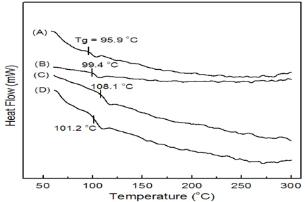
Figure 1 shows DSC curves for epoxy/silica microcomposites with various contents of epoxysilane-treated silica (55, 57, 60, and 63 wt%) at a heating rate of 10℃/min, where all samples were pre-cured at 100℃ for 2 h after curing at 140℃ for 16 h. No curve showed exothermic heat above Tg, indicating that these systems were completely cured without remaining unreacted functional groups that could generate heat under the cure conditions of this measurement.
As the silica content increased, Tg increased until 60 wt% silica and decreased after that. The Tg of 55 wt% silica was 95.9℃ and that of 60 wt% silica was 108.1℃, which was higher by 12.2℃. This indicated that the crosslink density of the epoxy/silica system became higher through the cure reaction between epoxy groups on the silica surface and the curing agent in the epoxy matrix and the physical crosslinking also increased due to hydrogen bonding between hydroxyl groups on the silica surface and hydroxyl groups generated from the epoxy reaction. However, if too much silica content filled into the epoxy matrix during the cure process, the silica particles disturbed the mobility of the epoxy functional groups, so that crosslink density became lower. This could be confirmed from the fact that Tg of 63 wt% silica (101.2℃) was 6.9℃ lower than that of 60 wt% silica (108.1℃).
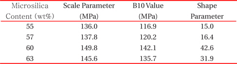
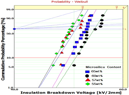
Weibull statistical analyses for AC insulation breakdown strength of epoxy/silica composites with four different silica contents are shown in Fig. 2, and the shape and scale parameters and B10 value were obtained from the Weibull plots and listed in Table 1. Here, the shape parameter could be obtained from the slope, meaning the data distribution, and the scale parameter represented the tensile strength, by which 63.2% of the cumulative probability was expected to break. The B10 value referred to the electrical breakdown strength at which 10% would break (90% would survive) under an applied high voltage [7]. The scale parameter increased until 60 wt% silica and decreased after that. This tendency was similar to that of Tg. The maximum electrical breakdown strength, 54.0 kV/2 mm was seen in the 60 wt% silica system, which was 109% higher than that of the 55 wt% silica system and 104% higher than that of the 63 wt% silica system. This means that the well dispersed microsilicas effectively interrupted the propagation of the electrical trace; however, too much silica content resulted in adverse effects on the electrical breakdown of the epoxy/silica system.
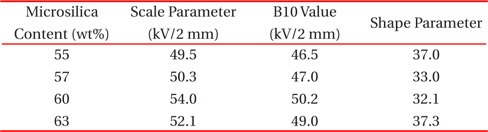
Weibull parameters for electrical breakdown strength in epoxy/silica system, obtained from Fig. 2.
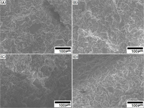
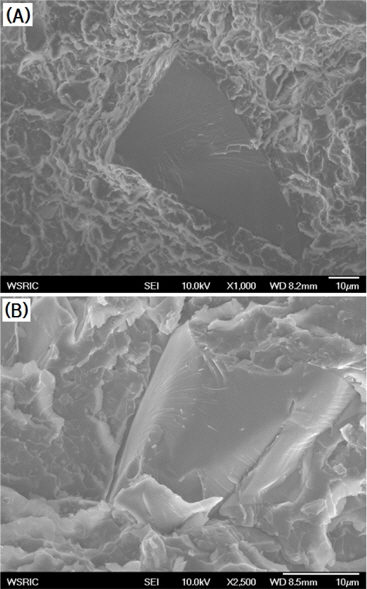
To study the interface between the epoxy and silica, SEM observations were carried out (Fig. 3). There was no gap in the interface of epoxy/silica (60 wt%) system as shown in Figure 3(A), while a broad gap was seen in Fig. 3(B). Thus, the barrier effect decreased due to the broad gap, so electrons could relatively easily flow around the interface between the silica and epoxy matrix. No gap in the interface of epoxy/silica (55 wt% and 57 wt%) was observed, which was not shown in Fig. 3.
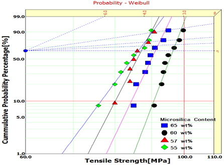
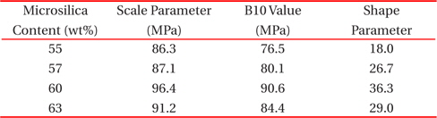
Figure 4 shows Weibull plots for tensile strength of epoxy/silica composites with different silica contents, and the Weibull parameters were obtained. The statistical analysis showed that the scale parameter of epoxy/silica (55 wt%) was 86.3 MPa with a shape parameter of 18.0, and that of epoxy/silica (60 wt%) was 96.4 MPa with a shape parameter of 36.3. The B10 value for epoxy/silica (55 wt%) was 76.5 MPa and that for epoxy/silica (60 wt%) was 90.6 MPa, 118% higher. The B10 value refers to the tensile strength at which 10% would break (90% would survive) under a tensile test [7]. When microsilica was added to an epoxy matrix, the silica can anchor the epoxy chains by covalent bonding and hydrogen bonding so that the mobility of the epoxy chains became disturbed; thus, the tensile strength increases.
As the filler content increased, the surface area increased, so that the bonding density increased and therefore mechanical strength increased.
[Table 2.] Weibull parameters for tensile strength in epoxy/silica system obtained from Fig. 4.
Weibull parameters for tensile strength in epoxy/silica system obtained from Fig. 4.
Microscopically, the fracture surfaces of epoxy/silica composites after tensile testing are shown in Fig. 5. Fracture was initiated from the interface between the epoxy and silica and the roughness of the surface was caused mainly by the generation of new crack fronts ahead of the primary crack and the interconnection of these new cracks on the different fracture systems. The high internal stress generated ahead of the front of the primary crack caused new cracks and cracks propagated rapidly.
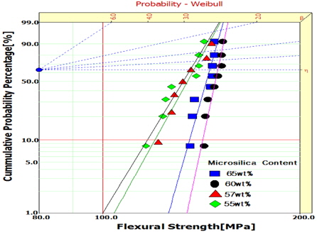
Weibull plots for flexural strength of epoxy/silica composites with different silica contents are shown in Fig. 6 and the Weibull parameters were listed in Table 3. The same tendency was seen and the maximum value, 149.8 MPa was obtained from the epoxy/silica (60 wt%) composite.
[Table 3.] Weibull parameters for flexural strength in epoxy/silica system obtained from Fig. 6.

Weibull parameters for flexural strength in epoxy/silica system obtained from Fig. 6.
Epoxy/silica microcomposites for use in electrical insulators for outdoor applications were prepared by mixing a cycloaliphatic epoxy resin (diglycidyl 1,2-cyclohexanedicarboxylate), a curing agent (4-methyl-1,2-cyclohexanedicarboxylic anhydride) and epoxysilane-treated microsilica (55, 57, 60, and 63 wt%). Then, mechanical and electrical properties were investigated. As silica content increased, Tg, electrical breakdown strength, tensile strength, and flexural strength increased until 60 wt% silica and decreased after that. In the epoxy/silica (60 wt%) system, maximum values for electrical breakdown strength, tensile strength and flexural strength were 54.0 kV/2 mm, 96.4 MPa and 149.8 MPa, respectively. This was due to covalent bonding and hydrogen bonding between the epoxy matrix and the silica.