Hyperthermia is a heat treatment for malignant tumors that has few side effects on patients. The cytotoxic effect of heating within the 43℃ to 47℃ temperature range has been studied, and many studies have reported that the condition of the cancers and tumors improved in
A circularly rotated array is proposed in this paper to enhance heating uniformity when a 2 × 2 array is required. Heating uniformity is enhanced by phase control in a dual polarized array applicator, which causes destructive interferences instead of constructive interferences in the center. This applicator can be applied to distribute heat uniformly when the target treatment area is smaller than 9 × 9 cm2.
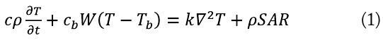
The specific absorption rate (SAR) is the dominant factor in the bio-heat equation, which defines the increase in human temperature caused by microwaves. This equation starts from the relation between the SAR and the temperature increase.
Energy flows created by heat transfer are added to the equation to conserve energy. This equation includes the SAR, the temperature increase, and energy flows with thermal conductivity and blood perfusion. Metabolic heat is ignored because it is so small compared to the other terms [12,13]:

The specific heat capacity (
A bolus layer helps impedance matched to the applicator and protects the skin from overheating by cooling. An acryl case is used to maintain the bolus layer. The applicator is fabricated on a 1-mm-thick FR-4 substrate. Microwave and thermal simulations are performed with a 3D CST full-wave simulator.
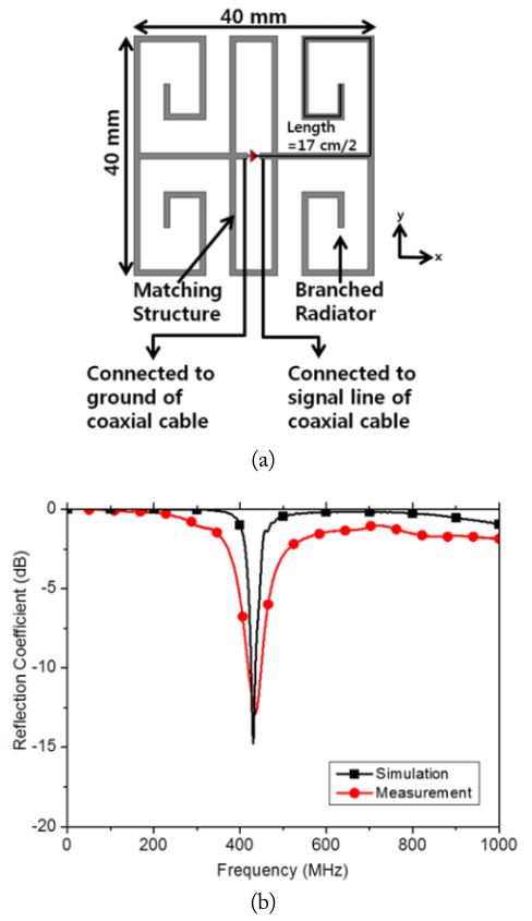
A half-wavelength dipole at 433 MHz is 17 cm long in a non-free space environment that consists of a phantom, bolus, and substrate. The branched dipole in Fig. 1(a) has a divided bent arm to decrease the size and a square shape to match the array. The matching structure is a complement of the branched dipole radiator as a branched magnetic dipole by providing the opposite reactance. The branched dipole element is matched to be operated at 433 MHz. The reflection coefficient is presented in Fig. 1(b).
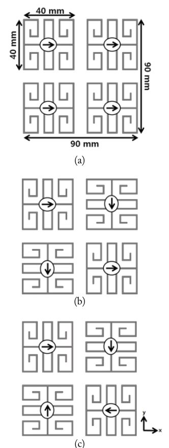
The configurations of 2 × 2 array applicators for 433 MHz are presented in Fig. 2. The element size is 4 × 4 cm2, and the gap between the elements is 1 cm. The gap is determined as the smallest value possible while avoiding significantly degrading the applicator’s reflection coefficient. The dual polarized lattice array (DPLA) was studied in a previous work by rotating the elements of a single polarized array (SPA) 90° in different directions to eliminate interference between neighboring elements, which are shown in Fig. 2(a) and (b), respectively [8]. The simulations are performed under the same conditions as the previous work. The dual polarized circularly rotated array (DPCRA) is proposed in this paper to enhance the heating uniformity of a small treatment area with a 180° phase shift of two elements of the 2 × 2 array.
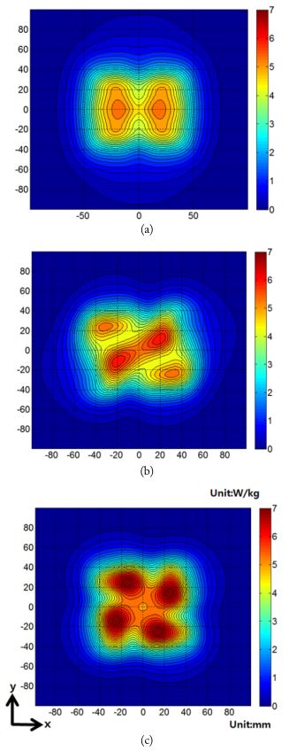
The SAR distribution of the 2 × 2 SPA in Fig. 3(a) has interferences between elements that cause element mismatches. The elements are rotated 90° alternatively for the DPLA in Fig. 2(b) to reduce interference between adjacent elements by having them perpendicular polarization. The DPCRA in Fig. 1(c) is applied to enhance uniform heat patterns by creating 180° phase differences between two elements in the second row. The DPCRA has destructive interference at the center whereas the DPLA has constructive interference at the center. The destructive interference prevents overheating at the center.
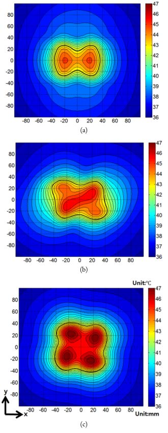
The temperature distributed by the array applicators with 20-W power is displaced as shown in Fig. 4. Each element is supplied by 5-W power for 60 minutes. The temperature distribution is calculated by the bio-heat equation, which includes the temperature increase by the SAR, blood circulation, and heat conduction. The maximum temperature of the SPA, DPLA, and DPCRA is 45.1℃, 45.9℃, and 46.4℃, respectively. The area inside the black line is the treatment area, which is between 43℃ and 47℃. The effective treatment area rate is between 43℃ and 47℃ compared to the applicator aperture. The effective treatment area rates compared to the 9 × 9 cm2 applicator are 38.6%, 57.2%, and 71.5% for the SPA, DPLA, and DPCRA, respectively. The DPCRA has the most advantage in the 2 × 2 array, which has the highest effective treatment area and the lowest distortion in heating patterns.
The performance of the proposed applicator with a solid phantom is measured for confirmation. The relative permittivity and conductivity of the solid phantom are 53 and 0.82 (S/m), respectively.
Measurements that use a solid phantom are not the same as a human body. No blood circulates in the phantom; thus, the measurement cannot be performed and analyzed in the same condition as in previous simulations. The heat is measured with homogeneous material that does not include blood circulation.
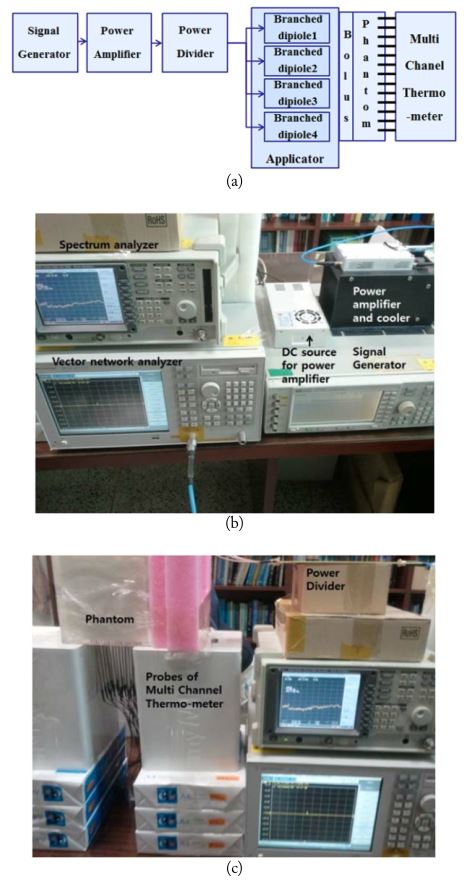
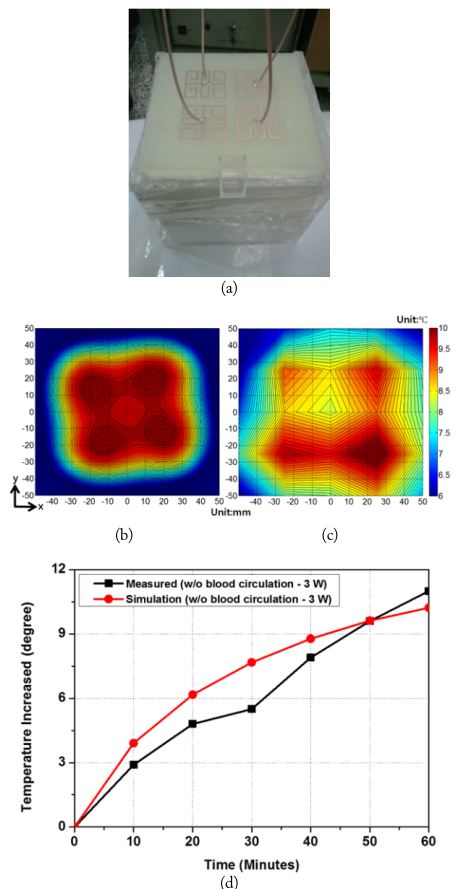
The heat distribution measurement system for the 2 × 2 DPCRA with a body phantom is presented in Fig. 5. The power for each dipole element is 34.7 dBm (= 3 W) for the 2 × 2 DPCRA. The power of the element is verified by comparing the measurement and the simulation in the same condition in which blood circulation is absent. The temperature increase due to the applicator in the phantom is measured with a multichannel thermometer at the other side of the applicator. The multi-channel thermometer has 24 probes and a data logger to manage real-time temperature data for 24 positions of the phantom. The temperature increase is measured with a fabricated applicator that includes a bolus, phantom, and multi-channel thermometer. The bolus case is made with the FR-4 substrate etched copper strip structure and acryl. The simulation and measurement are performed with the bio-heat equation without the blood circulation term because the solid phantom has no blood circulation. The 2 × 2 DPCRA and the results are shown in Fig. 6. The temperature is simulated to verify the temperature increase shown in Fig. 5. The simulation is performed in the same condition as the measurement.
The measurement and simulation without blood circulation heat distribution are shown in Fig. 6(b) and (c). Each element is supplied with 3-W power for 60 minutes. There is a distortion due to the mismatch and non-equal division of power to the elements during the measurement in Fig. 6(c). The temperature increases in the measurement and the simulation are shown in Fig. 6(d). The results show similar temperature increase intervals in the same conditions.
A circularly rotated array for a dual polarized applicator in a superficial hyperthermia system is proposed. This applicator has higher SAR uniformity than a single polarized array applicator because the dual applicator rotates each element for perpendicular polarization between adjacent elements. The circularly rotated array provides a more effective treatment area than the lattice array when a 2 × 2 dual polarized array is fitted to the treatment area. The effective treatment areas compared to the applicator areas are 38.6%, 57.2%, and 71.5% for the SPA, DPLA, and DPCRA, respectively. The measurement system is set up to provide sufficient power to heat the phantom and measure real-time temperature distribution. The simulation and measurement results match and validate the use of the proposed applicator for medical equipment.