Archimedean spiral antennas belong to a class of travelingwave wideband antennas that radiate a circularly polarized (CP) wave. The primary radiating elements of these antennas can be single-arm [1], two-arm [2–4], or four-arm [5] configurations with a large number of turns. Four-arm spiral antennas are considerably superior in performance to their single- and twoarm counterparts [6]. However, the four-arm spiral antenna generally requires a feed that has four output lines with equal amplitudes and a sequentially rotated phase [7]. This feeding structure contains a 1-to-4 power combiner/splitter that is generally complex, bulky, and expensive. In addition, the spiral antennas need a balun in the feed for matching to a 50-Ω coaxial cable since the input impedance is usually high (approximately 188-Ω for a self-complementary spiral antenna in free space) [8,9]. As a result, the design of four-arm spiral antennas faces the main challenge of implementing a simpler feeding structure.
On the other hand, short Archimedean spiral antennas [10–13], which are also referred to as curl antennas, behave as resonant types of antennas. These antennas are mechanically simple and produce CP radiation from a single feed point without the need for an external circuit; i.e., the antennas can be directly matched to a 50-Ω coaxial line. The selected curl antenna is placed approximately a quarter wavelength of the considered medium above a large perfect electric conductor surface, consequently, it can provide a good impedance matching and a good CP radiation over a bandwidth of approximately 10%. The radiation patterns of these antennas, however, are not very symmetric due to the single-arm configuration.
This paper introduces a single-feed four-arm curl antenna backed by a cavity reflector for global positioning systems (GPS) applications. A pair of vacant-quarter printed rings is employed in the feed of the radiator for direct matching to a 50-Ω coaxial line and to produce a CP radiation. The incorporation of the cavity-backed reflector [14,15] is a simple technique to improve the CP radiation characteristics in terms of 3-dB AR bandwidth and high-front-to-back ratio. The resulting antenna is characterized first with the ANSYS-Ansoft High Frequency Structure Simulator (HFSS) [16] and its simulated performance is then verified by measurements. In comparison with the previous wide-beam GPS antennas [14,15], the proposed antenna yields the same CP radiation performance with smaller antenna dimensions.
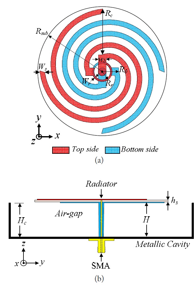
Fig. 1 shows the geometry of the proposed antenna composed of a four-arm curl radiator, a coaxial line, and a reflector. The curl radiator, which is a four-arm Archimedean spiral antenna with a small number of turns, was built on both sides of a circular Rogers RO4003 substrate with a radius of
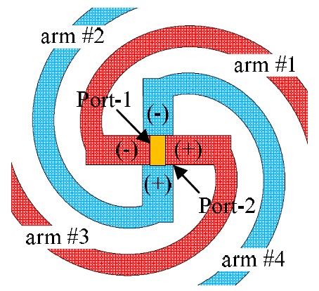
The curl antenna normally behaves as a resonant antenna and its input impedance depends on the number of turns, the spacing between turns, and the width of arm as well as the dielectric substrate (permittivity and thickness). Accordingly, the input impedance of the four-arm curl antenna can be predictively determined to match directly to a 50-Ω coaxial line. An ideal four-arm curl antenna, as shown in Fig. 2, was chosen for the initial design of the radiator and characterized by the HFSS software. The arms were placed on both sides of a circular Roger RO4003 substrate; the blue arms (#2 and #4) were on the bottom side of the substrate and the red arms (#1 and #3) were on the top side of the substrate. Referring to Fig. 1(a), the arm was formed by a center position of (0, 0, 0), a direction vector (0, 0, 1),
[Fig. 2.] High frequency structure simulator simulation modeling for an ideal four-arm curl antenna.

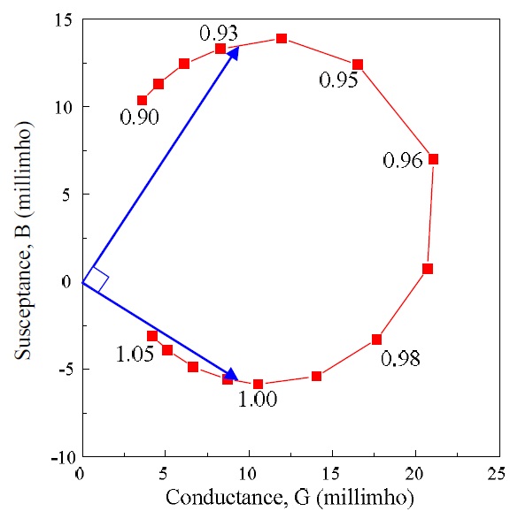
On the other hand, a single feed crossed dipole antenna [17] could generate CP radiation if the lengths of the dipoles are chosen such that the real parts of their input admittances are equal and the phase angles of their input admittances differ by 90º. At the desired frequency, the longer one has an inductive reactance, while the shorter one has a capacitive reactance. According to these conditions, the four-arm curl antenna could radiate a CP wave with a single feed. The required power and phase relationships can be obtained by proper choice of the number of turns for each arm of the antenna. This is observed in Fig. 4, which shows the input admittance of the ideal four-arm curl antenna (Fig. 2) at 1,575 MHz for different numbers of turns (
2. Four-Arm Curl Antenna Fed by Double Vacant-Quarter Printed Rings
The condition for CP radiation mentioned in the subsection A can be obtained in two equal length dipoles with a single feed by using a pair of vacant-quarter printed rings [14,15]. Accordingly, this approach is applied to the four-arm curl antenna with the same number of turns for all arms in order to produce the CP radiation and direct matching to a single 50-Ω coaxial line. The presence of the printed rings slightly changed the antenna geometry shown in Fig. 1(a) when compared with the ideal design (Fig. 2). The antenna was optimized for a minimum AR value at the GPS L1 frequency. Referring to Fig. 1(a), the antenna design parameters were as follows:
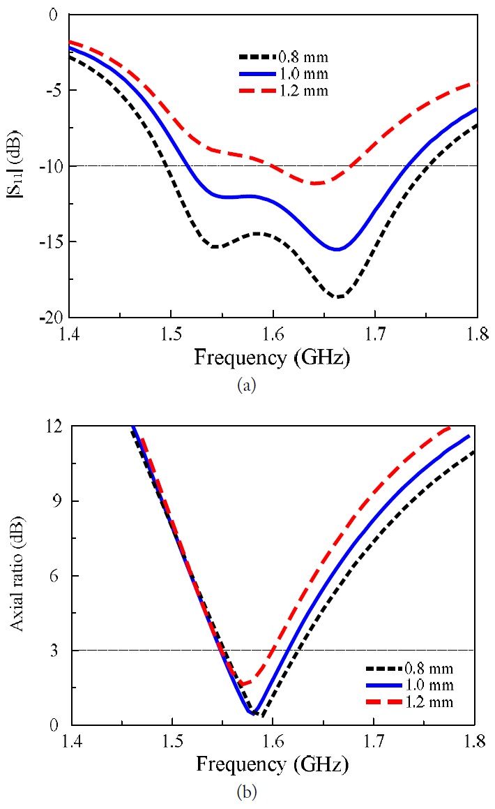
The role of the printed ring was demonstrated by investigating the performances of the antenna with different values of its design parameters (
The simulated performances of the four-arm curl antenna in free space are shown in Fig. 7. The antenna yielded an impedance matching bandwidth of 12.9% (1,520–1,730 MHz) for |
3. Four-Arm Curl Antenna Incorporating with the Cavity-Backed Reflector
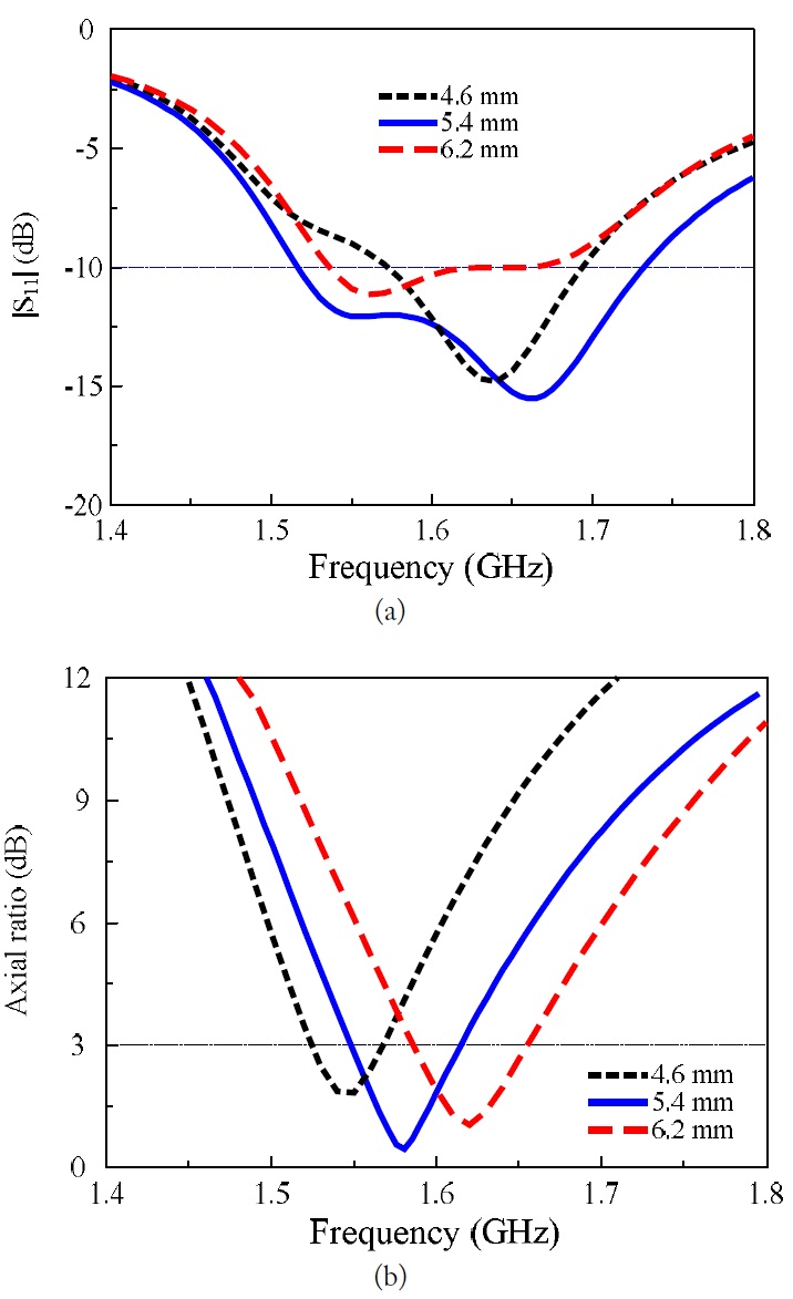
The radiation characteristics were improved and a wide beamwidth and a high front-to-back ratio were obtained by introducing a cavity as a reflector in the four-arm antenna. Both square and circular reflectors were used in the optimization process for the curl antenna. However, the square one, as shown in Fig. 1(b), was chosen for the final design based on a compromise between a small antenna footprint and good CP radiation. The proposed design with the cavity-backed reflector was confirmed to improve the radiation characteristics by examining the antenna performances at different heights (
[Table 1.] Characteristics of the four-arm curl GPS antenna for different heights of the cavity
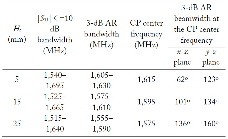
Characteristics of the four-arm curl GPS antenna for different heights of the cavity
IV. MEASURED AND SIMULATED RESULTS
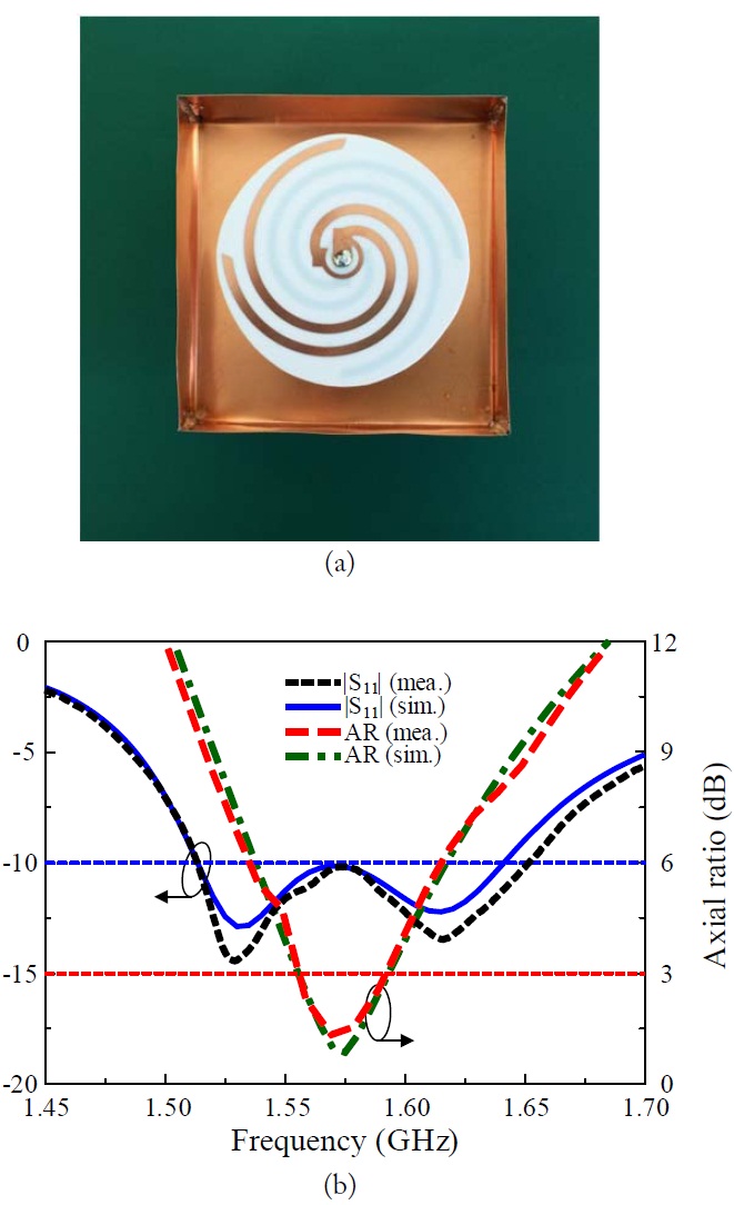
The composite cavity-backed four-arm curl antenna was fabricated and measured. The curl radiator was built on both sides of a circular Rogers RO4003 substrate with a copper thickness of 20 μm via standard etching technology. The cavitybacked reflector was constructed using five copper plates (one 90 × 90 mm2 and four 25 × 90 mm2) having a thickness of 0.2 mm. A sample of the proposed antenna (Fig. 8(a)) was used for the measurements; an Agilent N5230A network analyzer and a 3.5-mm coaxial calibration standard GCS35M were used for the input impedance measurement of the antenna. Another Agilent E8362B network analyzer and two identical standard horn antennas were used for the radiation pattern measurements, which were conducted in a full anechoic chamber with the dimensions of 15.2 m (
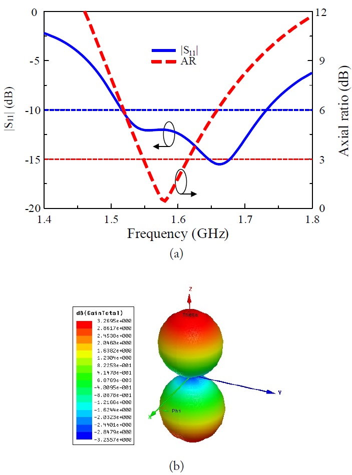
Fig. 8(b) shows the measured and simulated reflection coefficients for the proposed antenna. The measured bandwidth was 8.66% (1,514–1,651 MHz) for |
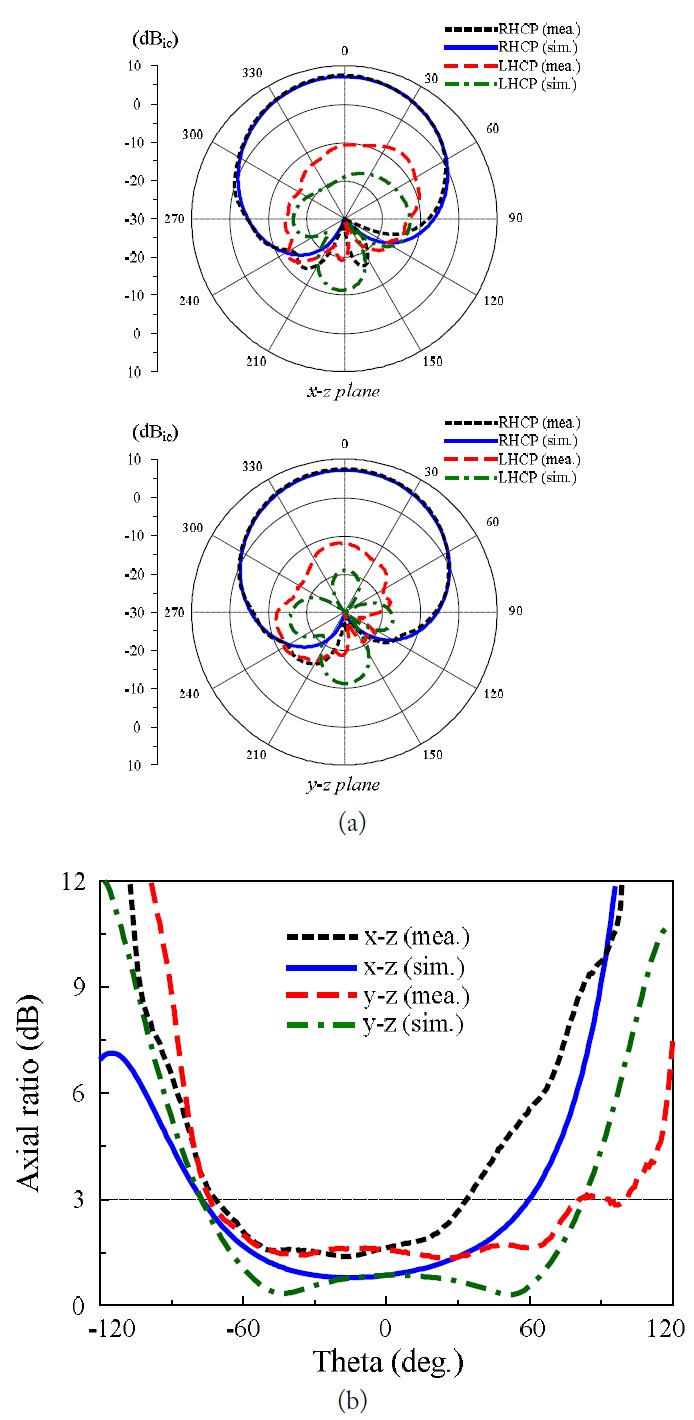
Fig. 9(a) shows the 1,575 MHz radiation pattern of the antenna with RHCP, symmetrical profile, and wide beamwidth in both
A single-feed composite cavity-backed four-arm curl antenna has been introduced. The antenna with overall GPS L1 frequency size of 0.4725 λo × 0.4725 λo × 0.13 λo resulted in a |