Corrosion is an important age-related degradation problem that has a great impact on the service life of marine structures. Since the 1950s, the construction time of ships and offshore structures has been significantly reduced by the development of welding and maintenance technology. With maintenance technology advancing at a fast growing rate, the structural failure due to in-service damage is decreasing. These advances, along with other technical developments, have extended the lifespan of ships and offshore structures by two or three times.
Historically, various technologies for preventing corrosion have been suggested, such as corrosion addition, coating, cathodic protection, ballast water deoxygenation, and chemical inhibition (Paik and Melchers, 2008). Of these technologies, coating and corrosion addition are the two most widely adopted technologies by ship designers and builders to protect structural members from corrosion degradation because of their cost effectiveness, simple practicability, and relevance.
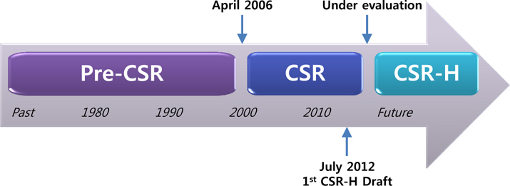
Before the introduction of CSR, corrosion addition rules were developed and maintained by individual classification bodies, a period known as pre-CSR. To achieve robust and safer ships, the IACS adopted CSR for oil tankers and bulk carriers on 1st April 2006, at which the corrosion additions for oil tankers and bulk carriers were specified (IACS, 2006a; 2006b). However, the CSR for oil tankers and bulk carriers were developed independently by different teams using different technical approaches. During the review of the CSR, industry stakeholders urged the IACS to harmonise the key technologies used to derive the rules. The IACS agreed and was committed to develop a harmonised version of the rules (IMO, 2012). The new structural rules are known as CSR-H (IMO, 2012), as shown in Fig. 1. The outcome of the verification will be effective soon.
The CSR-H is made up of common “general hull requirements” for both ship types, and separate parts for “ship-type specific” requirements applicable to oil tankers and bulk carriers, respectively (Kim and Cheng, 2012). The rules on the corrosion additions for each ship type are expected to be located in the “ship type specific” parts, and corrosion additions can be defined for a range of cargo hold circumstances for each ship type.
This study investigates the historical trend of corrosion additions for double hull oil tankers and their effect on the ultimate strength performance of hull girders. For comparison, two other corrosion models namely UGS model, a new corrosion model suggested by the UGS and the time-dependent corrosion wastage model are also examined. Many Greek shipowners have called for larger corrosion additions. However, no action has hitherto been taken to change the current corrosion addition rules. This matter has led to the UGS developing an increased corrosion addition model (Gratsos et al., 2009; 2010). Four representtative classes of double hull oil tanker structures, namely Panamax, Aframax, Suezmax, and VLCC, are used to trace the general trend in corrosion addition effects. In addition, bulk carriers have been considered to draw the general tendency using similar procedure as present study by Kim et al. (2014b). The insights obtained in this study will help in understanding the trend in corrosion additions for double hull oil tankers and their effect on the ultimate strength performance.
GENERAL CORROSION ADDITIONS FOR TANKERS
>
Trend in corrosion addition rules for ship design
The CSR for corrosion additions were specified for double hull oil tanker and bulk carrier structures in early 2006 for several reasons (IACS, 2006a; 2006b) as follows: To reflect the experience and resources of all the classification societies (IACS members) in a set of unified rules.To remove the confusion surrounding the corrosion additions of different classification societies.To achieve a 25-year design life.To apply the net thickness approach to ultimate strength analysis for stiffened panels and the half corrosion addition approach for hull girders.
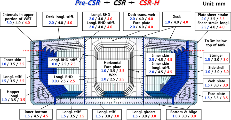
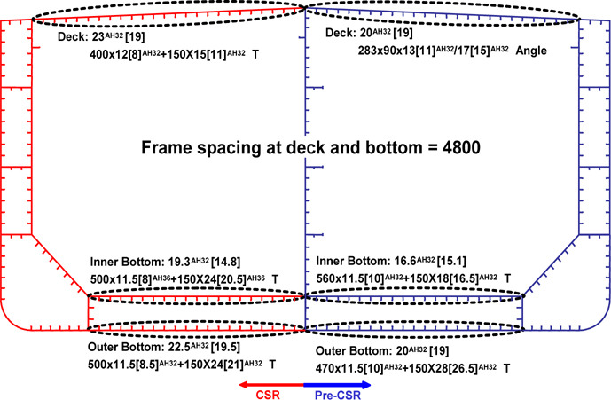
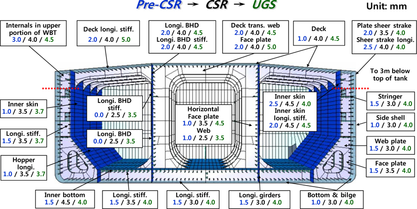
The historical trend in corrosion additions for each structural member for double hull oil tankers is presented in Fig. 2. The figure shows that there is no difference between the CSR and CSR-H, but the CSR corrosion additions are much greater than the pre-CSR corrosion additions. It seems that the specified CSR corrosion additions are sufficient, and thus the same additions have been included in the CSR-H. Of course, the approach between pre-CSR and CSR is originally differing from each other. The pre-CSR has adopted the net-scantling approach for ultimate strength analysis of stiffened panels and half corrosion addition deduced scantling approach for ultimate strength analysis of hull girders. However, the structural scantlings have been changed due to the different strength capacity requirements when the CSR was originally introduced in 2006, as shown in Fig. 3.
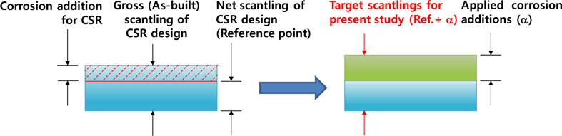
Four types of double hull oil tankers designed using the IACS CSR method are employed to avoid complex structural design selection problems. The net scantlings in the CSR design are taken as the reference scantlings in the present study, as shown in Fig. 4.
>
Other corrosion addition models
The TDCWM for ships and offshore structures (Paik et al., 2003a; 2003b; 2004; Guedes Soares et al., 2008) was deducted from the results of statistical analyses using real corrosion measurement data. As mentioned previously, two types of corrosion models (CSR and CSR-H) were also proposed based on real measured time-variant corrosion wastage. But, other types of TDCWM have been developed by researchers.
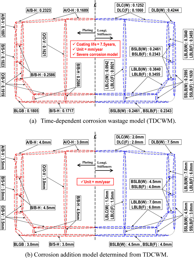
Recently, more refined time-dependent corrosion wastage model techniques have been proposed by Paik and Kim (2012) and applied to the various structures such as subsea well tube (Mohd Hairil and Paik, 2013) and subsea gas pipeline (Mohd Hairil et al., 2014). For the condition assessment of corrosion damaged structures, Paik et al. (2003a) developed two types of TDCWM for tankers that cover average and severe cases. Kim et al. (2012a; 2012b) performed an ultimate strength comparison study of hull girders and stiffened panels using the CSR corrosion addition and the average TDCWM. Their results showed that the difference in ultimate hull girder strength between the two corrosion models at the 25 years (net) scantling was around 10-20%. Recently, Kim et al. (2014a) investigated an ultimate hull girder strength of corroded Aframax class oil tanker under grounding damage. In the comparison in this study, a representative severe TDCWM for a double hull oil tanker (Paik et al., 2003a) is applied, as shown in Fig. 5 see
Moreover, the UGS suggested a new corrosion addition model (Gratos et al., 2009; 2010), as shown in Fig. 6, that reflects their experience of double hull oil tanker structures to reduce maintenance costs. The model meets with opposition from other shipowners who have confidence in the current maintenance of their ship.
Fig. 6 presents the UGS corrosion addition models for each structural member against other pre-CSR and CSR corrosion addition rules. The UGS corrosion additions are around 0.2
In the structural analysis of ships, global scantling check (hull girder) and local scantling check (stiffened panel) are performed sequentially.
Applied examples for hull girders
Four sizes of double hull oil tankers (Paik et al., 2012b) are selected as representative vessels to investigate the general trend in corrosion addition effects. The principal dimensions of each ship are illustrated in Table 1. The ALPS/HULL (2013) progressive hull collapse analysis program is used for the hull girder ultimate strength analysis. The details of ALPS/HULL program are described in Hughes and Paik (2010) and benchmark studies have been performed to verify its accuracy and efficiency (Paik et al., 2012a).
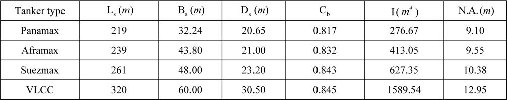
General mid-ship section information with principal dimensions of the target structures with net scantlings (reference point as illustrated in Fig. 4).
Vertical bending moments including hogging and sagging, which are the dominant loads for ships during operation period, are considered in the ultimate strength analysis for the gross scantlings, half addition scantling, and net scantlings of the ship. Only the average levels of initial distortions, which are performed by plate initial deflection and stiffener distortion, are considered. The weld-induced residual strength is not considered for hull girder strength analysis according to the CSR (IACS, 2006a).
Analysis results of hull girders
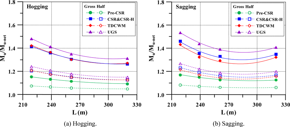
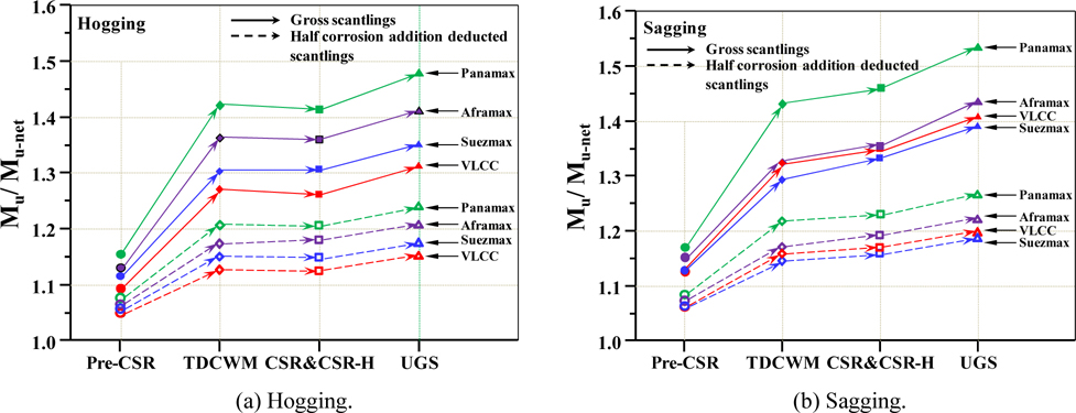
The ultimate hull girder strength analysis results for the four sizes of double hull oil tanker structures and the five types of corrosion addition models are compared in
[Table 2] Coefficients of the empirical formulas under vertical bending moments.
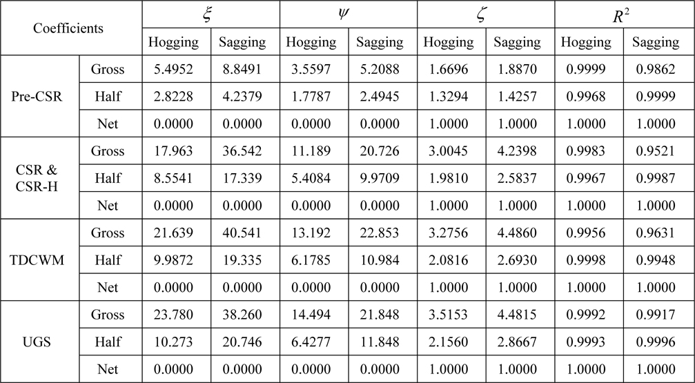
Coefficients of the empirical formulas under vertical bending moments.
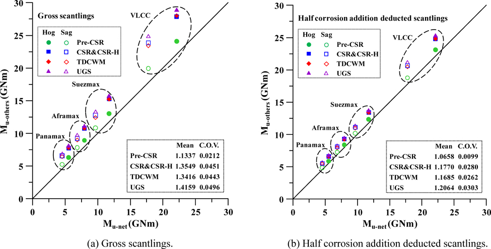
The mean value and Coefficient of Variation (COV) are presented in

The coefficients are as summarised in Table 2.
In a sagging condition, these empirical formulas cannot be applied to evaluate the residual strength performance when the vessel length is larger than 261.0
The differences in the mean values are presented in Figs. 8(a) and (b), and more details of the statistical analysis results are given in
For a hogging condition

For a sagging condition

The local scantlings are also investigated by applying the ALPS/ULSAP ultimate strength analysis program for stiffened panel. The details of ALPS/ULSAP program have been described in Hughes and Paik (2010) and benchmark studies for stiffened panels have been performed to verify the accuracy and efficiency about the ALPS/ULSAP program (Paik et al., 2012a).
Applied examples for stiffened panels
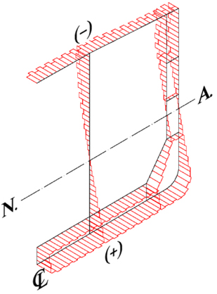
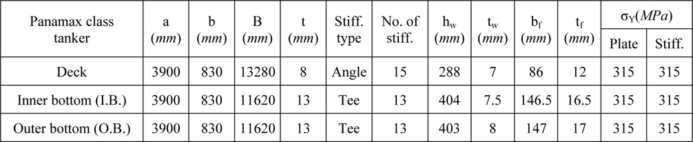
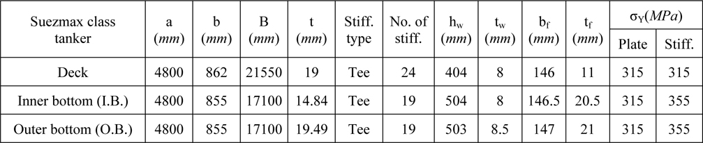
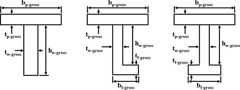
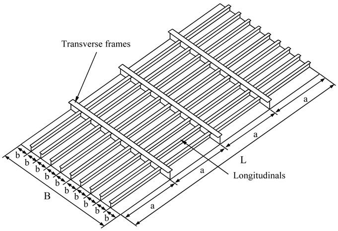
It is well known that maximum axial compression or tension are applied to the deck, inner bottom, and outer bottom stiffened panel structures, which are located far away from the neutral axis of the ship, as presented in Fig. 10 (Paik et al., 2013). The details of the selected three stiffened panels are presented in Table 3(a) to (d). Schematic diagram of stiffened panel is presented in Fig. 11 and the nomenclatures of the stiffener dimensions are illustrated in Fig. 12.

Properties of the stiffened panels of panamax class tanker with net scantlings based on Figs. 11 and 12.

Properties of the stiffened panels of aframax class tanker with net scantlings based on Figs. 11 and 12.

Properties of the stiffened panels of suezmax class tanker with net scantlings based on Figs. 11 and 12.
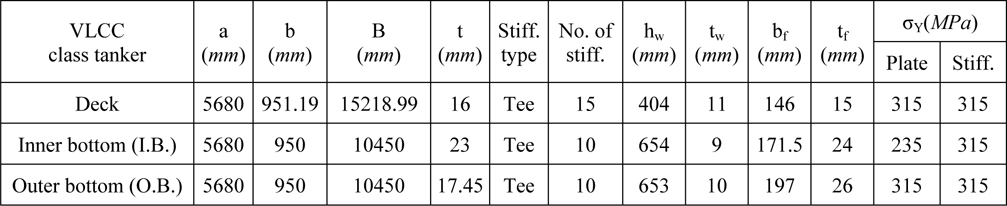
Properties of the stiffened panels of VLCC tanker with net scantlings based on Figs. 11 and 12.
Analysis results for stiffened panels
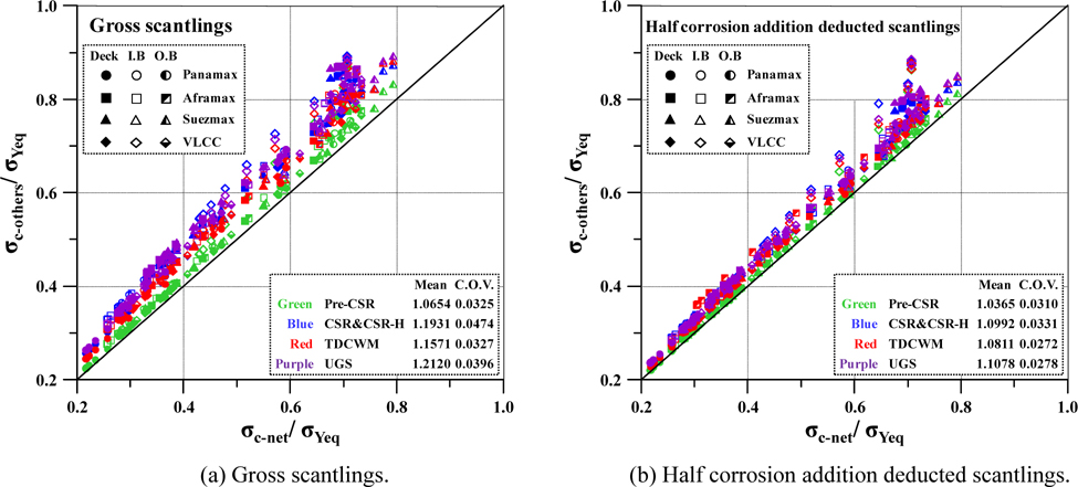
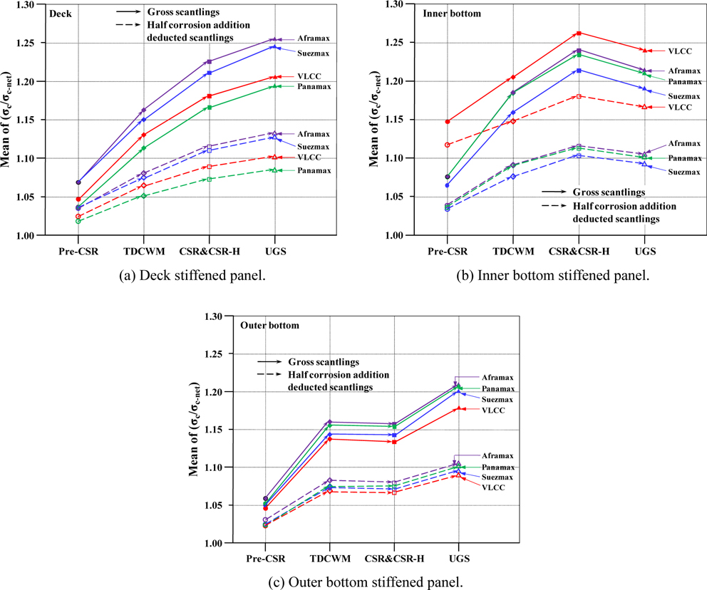
The capacity for biaxial compressive action () is compared and the obtained results are plotted in Figs. 13(a) and (b) with mean and COV values. The corresponding figures present the trend of the deviation in ultimate limit state of stiffened panels between net scantlings and the five corrosion addition models. The details of statistical analysis results (i.e., mean, standard deviation, and coefficient of variation) are as summarised in
From the mean values shown in Figs. 13(a)-(b), it is apparent that the ultimate strength capacity of the stiffened panels can be specified in the following order and the order of ultimate strength capacity would be linked with Figs. 14(a)-(c).
For deck stiffened panels

For inner bottom stiffened panels

For outer bottom stiffened panels

This study investigates the trend in corrosion additions in the structural design of ships and the effect of corrosion additions on the ultimate strength performance of four double hull oil tanker structures, namely Panamax, Aframax, Suezmax, and VLCC.
Five types of corrosion addition models, namely Pre-CSR, CSR, CSR-H, TDCWM, and UGS, are applied to investigate the general trend in corrosion additions. The ultimate strength performance of hull girders and stiffened panels are investigated in terms of the gross, half corrosion addition deducted, and net scantlings.
The net scantlings in CSR design are set as the reference scantlings from which the minimum required strength thickness is obtained and to which the additional corrosion additions (margins) of each corrosion models are added, as shown in Fig. 4. Based on these assumptions, empirical formulas are proposed for the ultimate hull girder strength performance of double hull oil tankers for the different corrosion addition rules. But, additional case studies for double hull oil tankers should be performed and considered to develop reliable empirical formulas.
The results are expected to be helpful in evaluating the effect of corrosion additions on the ultimate strength performance of double hull oil tanker structures and to help understand the history of structural design rules on corrosion. Future studies could investigate the effect of corrosion addition models on economics in terms of the consumption of steel and fuel ratio, and the effect of corrosion additions in bulk carriers.
CSR Common structural rule Ds Ship depth CSR-H Harmonised common structural rule hw Web height of stiffener Pre-CSR Structural rule applied before CSR I Moment of inertia TDCWM Time-dependent corrosion wastage model proposed by Paik et al. (2003a) Ls Ship length Mu Ultimate hull girder bending moment UGS Union of greek shipowners a Length of stiffened panel Mu_net Ultimate hull girder bending moment at net scantling B Breadth of stiffened panel t Plate thickness Bs Ship breadth tf Flange thickness b Breadth between longitudinal stiffeners tw Web thickness bf Breadth of flange σY Yield strength Cb Block coefficient