The utilization of abnormal information of symbolic gases to find active minerogenetic area is one of the important prospects in the current exploration of ocean floor resources (Kelley et al., 2002; Milkov et al., 2004; Lilley et al., 1995; Kelley et al., 1998; Radford et al., 1998; Houghton et al., 2001; Nakayama et al., 2002). Huang et al. (2012) proposed that the underwater environment (e.g., high pressure) makes underwater resource exploration increasingly challenging, especially in deep sea. Research shows that gases such as CH4, H2S, CO2 and H2 in seawater are important tracers for exploration of marine resources such as deep-sea hydrothermal fluids, cold spring, natural gas hydrate, and so on. Lilley et al. (1995), Kelley et al. (1998) and Radford et al. (1998) all suggest that the full analysis of gas type and content in sea water plays a significant role in marine scientific research and exploration of marine resources. Thus, it is necessary and critical to converse gases in seawater. If gases leak from the water with the change of the environmental factors such as temperature and pressure in the process of sampling, transmission and transfer, the collected data cannot accurately reflect the gas components in the samples (Huang et al., 2011).
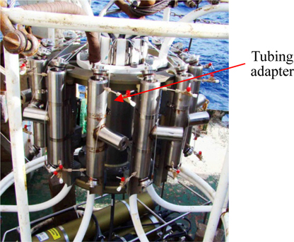
Tubing adapters, as connection devices are widely used to connect sampling chamber and sampling valve in GTWS. Tubing adapters with good sealing performance can ensure the transmission of seawater samples without gas leakage and can be repeatedly used. When the companies and institutes such as General Oceanics, HYDRO-BIOS and WHOI used engineering plastics and metal materials such as PVC, PTEF, PEEK, Stainless Steel 316 and titanium alloy to manufacture water samplers, only the anti-corrosion and preventing sample contamination were taken into account. Sealing performance of different materials, however, was analyzed insufficiently (Li, 2003; Taylor et al., 2006; Sauter et al., 2005).
In this paper, after the introduction of GTWS and its tubing adapters, the sealing performance of tubing adapters, tubes and water sampler bottle, each made of different materials, was analyzed by non-linear finite element contact analysis method with software ANSYS according to GTWS’s real condition. Furthermore, recommendatory materials match schemes of tubing adapters, tubes and water sampler bottle were derived both in theory and practice. The results of presented analysis provide theoretical guidance for engineering application of GTWS. In addition, the reliability and tightness of GTWS were tested respectively in tank and high pressure vessel. The sea trials were also carried out in the South China Sea to test the gas tightness of GTWS, and the gas-tight seawater samples were obtained by GTWS. The seawater samples could be transmitted without gas leakage nor contamination and the tubing adapters can be used repeatedly. The goals of no-contamination and non-leakage sample transmission were successfully achieved. Consequently, the sealing performance of the GTWS was verified both in theory and practice.
GAS-TIGHT DEEP-SEA WATER SAMPLER AND TUBING ADAPTERS
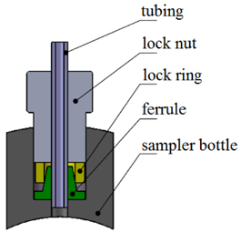
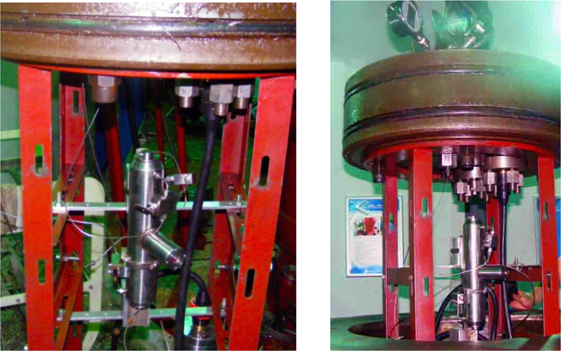
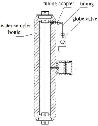
The integrity of gas content of seawater is required in marine scientific research and marine resources exploration and the GTWS is the major device of seawater sampling and storing, which is indispensable in seawater sampling. Tubing adapter is the key connecting device in GTWS, used to connect sampling chamber and sampling valves. Fig. 1 is the schematic diagram of a small volume GTWS developed by Zhejiang University and its prototype is shown in Fig. 2. With such sampler, about 180
THEORETICAL ANALYSIS OF TUBING ADAPTERS’S SEALING PERFORMANCE
In our research, the way of seal between tubing adapters and sampling chamber is static contact seal. Its sealing mechanism is to add pressure to the contact sealing surfaces to form a fully fitted sealing ring. The counterforce of the sealing ring is larger than the medium pressure, which can prevent the medium from entering thus the goal of sealing can be achieved. In the previous research of Gu (2000), on the micro level, the basic mechanism of static contact seal is that the sealing materials, in plastic or elastic deformation, will enter into the irregular matching surface to form a sealing ring. As a result, the leakage of the tubing adapters under different working conditions is limited within the allowable range (Gu, 2000).
Force per unit area of the mechanical seal face is called sealing pressure

Meanwhile, in order to ensure the reusability of the tubing adapters and also make sure that the sealing materials will not be damaged, tubing adapters and their contact surfaces must be within the range of elastic deformation. The sealing pressure

Therefore, it is possible to use the value of the sealing pressure
FINITE ELEMENT ANALYSIS OF THE TUBING ADAPTERS’S SEALING PERFORMANCE
Analyzing the sealing performance of tubing adapters is required to provide theoretical guidance for the recommendatory materials match schemes after the sealing mechanism is established. Because of the complexity of the actual situation, the exact analytical solution is very difficult to be obtained in theory. The studies of Song et al. (2010), Byun et al. (2011), Yu and Lee (2012) show that finite element analysis is used in many studies to investigate the static and dynamic characteristics of vehicles. Abid and Ullah (2007), Mathan and Prasad (2008), Krishna et al. (2007) and Subramanian et al. (2013) suggests that through the static structure analysis by finite element analysis software ANSYS, the transfer process and the entire coordination changing process of contact load can be reflected truly after the non-linear contact analysis on the assembly of the three-dimensional model by means of finite element method. After the description of the sealing mechanism, the sealing performance of tubing adapters, tubes and water sampler bottle made of different kinds of materials were analyzed by ANSYS according to real condition of GTWS, and the sealing pressure was calculated using static analysis. As a result, the recommendatory materials match schemes of tubing adapters, tubes and water sampler bottle were obtained. In order to ensure the unity of the finite element unit, when building the finite element model and loading the physical parameters, the units of length, force, elastic modulus and stress were taken as mm, N, MPa and MPa respectively.
>
Building geometric model of the tubing adapter
In our analysis, the tubing adapter selected to analysis is 1/4
>
Sealing pressure finite element analysis of different materials matches of tubing adapters
The materials' mechanical properties must meet the requirements, and their corrosion resistance should also be considered in the real working condition. According to the obtained design data, the water sampler bottles were made of Unplasticized Polyvinyl Chloride (UPVC) or Stainless Steel 316. Tubing adapters and tubing were made of PEEK or Stainless Steel 316. Thus different materials matches of the tubing adapters are available and shown in Table 1.
[Table 1] Materials matches of the tubing adapters.
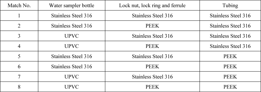
Materials matches of the tubing adapters.
The sealing performance of each materials match was analyzed respectively with finite element analysis software ANSYS according to real situation of GTWS. The sealing performance of eight different materials matches of the tubing adapters were compared afterwards.
The mechanical properties of UPVC, PEEK and Stainless Steel 316 adopted in this paper are shown in Table 2, the frictional numbers of each material pairs between UPVC (Zhang et al., 2012; Tolosa et al., 2010), PEEK and Stainless Steel 316 are defined in Table 3 (Wen, 2010) .
[Table 2] Mechanical properties of UPVC, PEEK and Stainless Steel 316.
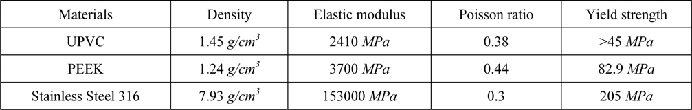
Mechanical properties of UPVC, PEEK and Stainless Steel 316.
[Table 3] Frictional numbers of each material pairs between UPVC, PEEK and Stainless Steel 316.
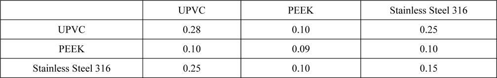
Frictional numbers of each material pairs between UPVC, PEEK and Stainless Steel 316.
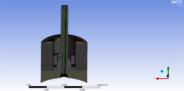
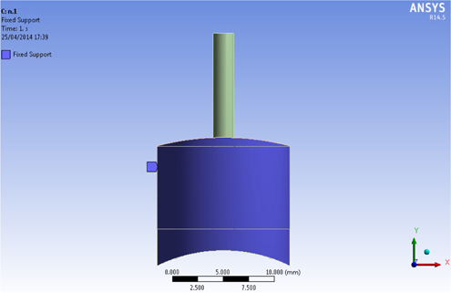
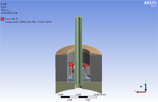
The geometry model of the tubing adapter was simplified by SOLIDWORKS so that the Finite Element model can be established in ANSYS Workbench. Characteristics of materials in Table 2 were set in Engineering Data module of ANSYS. PEEK and UPVC is defined as nonlinear character. Then the Workbench was used to mesh the model, shown in Fig. 5. There were 88926 units and 395945 nodes in the model. There were six kinds of 3D element used in the model, which were quadratic hexahedron, quadratic wedge, quadratic quadrilateral contact, quadratic quadrilateral target, quadratic triangular contact and quadratic triangular target. Constrains of the model are shown in Fig. 6. The outermost surfaced is fixed, and the model has a symmetric constraint on the symmetric region. Considering the real working condition, the upper surface of the lock ring was loaded with an initial force from 0 to 500
>
Results of finite element analysis
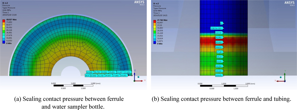
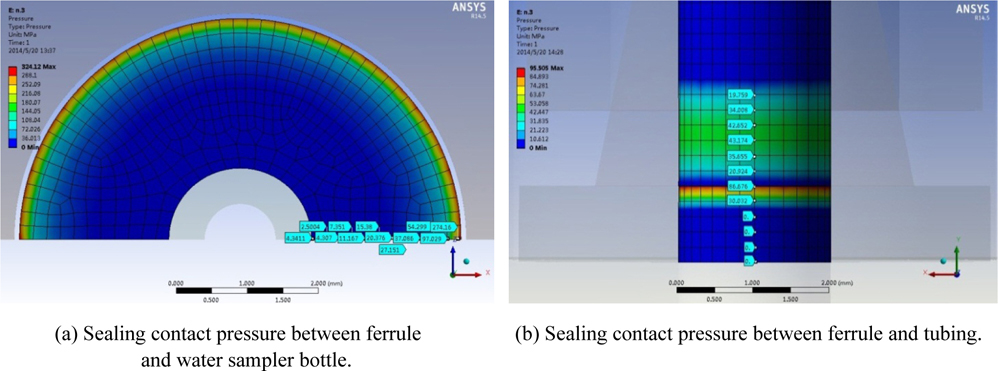
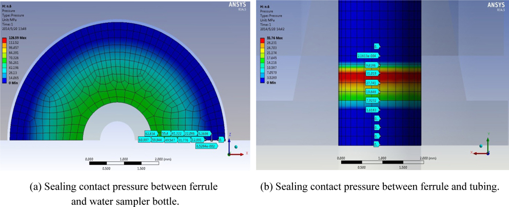
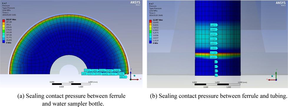
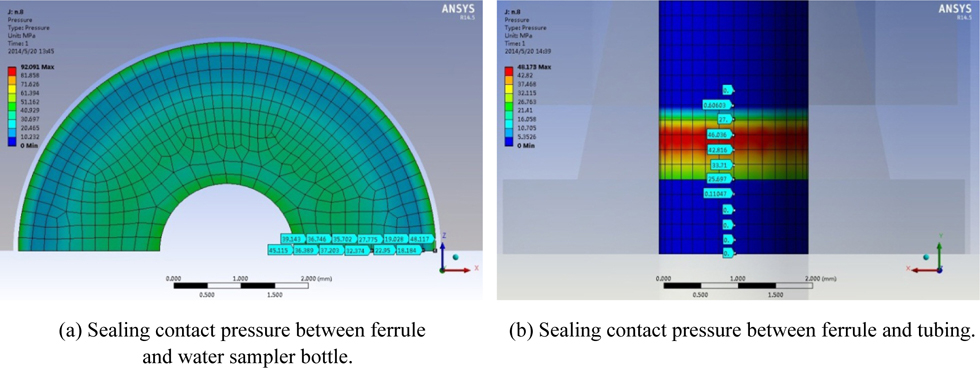
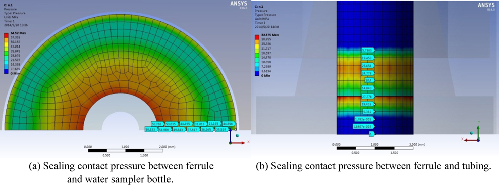
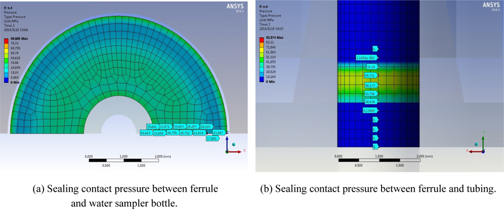
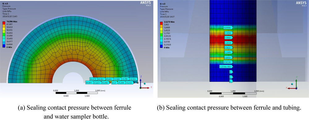
In the same external conditions, the same load was applied to the tubing adapter of different materials. Through the comparative analysis of the tubing adapter of different kinds of materials, distribution maps of sealing contact pressure between ferrule and water sampler bottle as well as ferrule and tubing can be obtained. The sealing contact pressure distribution maps of the eight materials matches are shown from Figs. 8-15 in a row.
From Figs. 8 to 15, in each figure the sealing contact pressure of ferrule and water sampler bottle is shown in left as (a), and ferrule and tubing shown in right as (b). The colors of the contact area of ferrule and water sampler bottle in Fig. 10(a) and Fig. 14(A) are either dark blue or light blue, which means that the sealing contact pressures of these two materials matches are quite low and their sealing performances are not satisfying. However, the colors of the other six materials matches are either red or yellow, which indicate that the other six materials matches’ sealing contact pressure are high enough, and their sealing performance is acceptable. Therefore, from the point view of the sealing contact pressure of ferrule and water sampler bottle, it can be preliminarily deduced that material match No.3 and match No.7 are not reasonable and the other six matches are preferable from Figs. 8(a)-15(a). Because the specific sealing contact pressures which are indicated by the colors of the contact area of ferrule and tubing in Figs. 12(b) and 14(b) are rather smaller than the others, it means that the sealing contact pressures of these two materials matches are quite low and their sealing performances are not satisfying. So it can be preliminarily deduced that match No.5 and No.7 are not reasonable and the others are preferable from Figs. 8(b)-15(b).
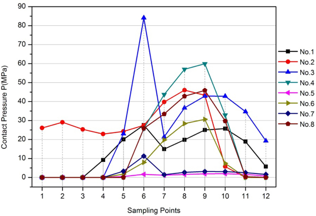
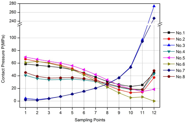
In Fig. 16, the sealing pressures between ferrule and water sampler bottle of different material matches are graphed in eight colorful broken lines and each line is mainly composed of twelve sampling points evenly from the sealing pressure distribution maps. In Fig. 17, for the sealing pressures between ferrule and tubing of different material matches, the same eight broken lines are drawn but with each line composed of twelve sampling points.
In the analysis of the ferrule and water sampler bottle, 12 sampling points were picked up evenly along the ridge of lower surface in the bottom plane section of the water sampler ferrule section, and the interval between two points is 0.29
From Fig. 16, it can be perceived that the sealing pressure of materials match No.3 and materials match No.7 from spot 1 to spot 6 are relatively lower than the other materials matches. It also means the effective sealing lengths of materials match No.3 and materials match No.7 along the sealing radial ridge are relatively small, fails to provide reliable sealing performance. This is consistent with the deduction of the sealing pressure maps. From Fig. 17, it can be seen that the sealing pressure of materials match No.5 and materials match No.7 in all spots are much lower than the others. This is also consistent with the deduction of the sealing pressure maps.
In conclusion, materials match No.3, No.5 and No.7 are not recommended in this case, the combination types of which fails to satisfy the sealing requirement of GTWS. On the contrary, match No.1, No.2, No.4, No.6 and No.8 are recommended as good materials combinations of water sampler bottle, lock nut and ferrule, which is summarized in Table 4.
[Table 4] The recommended materials matches.
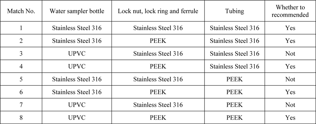
The recommended materials matches.
TANK AND HIGH PRESSURE VESSEL TESTS
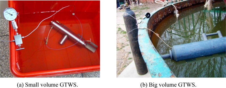
The GTWS’s tank tests were conducted, seen in Fig. 18, and the results were shown in Table 5. It can be seen that the pressures of both the small and big volume GTWS remain the same after 22 (for small volume) or 8 (for big volume) hours of pressure maintaining tests. The tank tests verify the leak proof of the tubing adapters under constant interior pressure.
[Table 5] Results of GTWS’s tank tests.
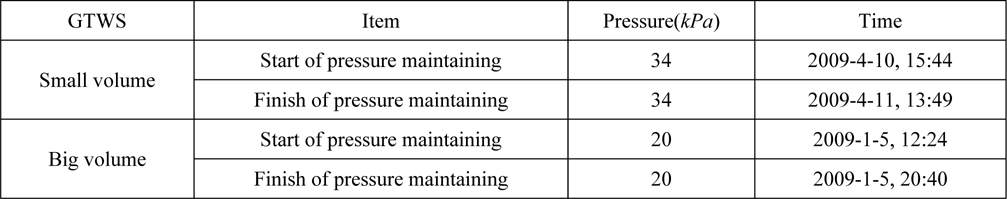
Results of GTWS’s tank tests.
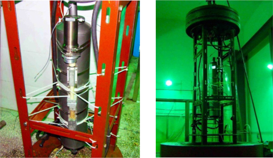
The reliability of the big volume GTWS was also tested in the high pressure vessel with 40
The tightness of the small volume GTWS was also tested in the same high pressure vessel as shown in Fig. 20. The pressure maintained inside high pressure vessel is also set as 40
[Table 6] Results of tightness test of the small volume GTWS in the high pressure vessel.

Results of tightness test of the small volume GTWS in the high pressure vessel.
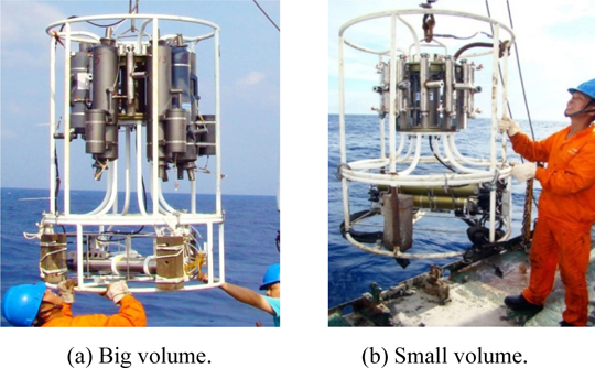
The first sea trial was carried at the 3930 meters depth of the South China Sea, 117d15.6782′E, 17d41.5811′N, June 1st, 2009. The second sea trial was carried at the 960
[Table 7] Field measuring and analyzing results of the contrast test in 3930 meters depth.
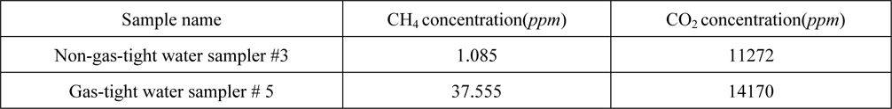
Field measuring and analyzing results of the contrast test in 3930 meters depth.
[Table 8] Field Measuring and analyzing results of the 960m depth in active region of cold seep.
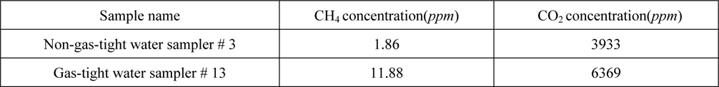
Field Measuring and analyzing results of the 960m depth in active region of cold seep.
In this paper, the sealing performance of tubing adapters in gas-tight deep-sea water sampler is studied. The main conclusions are drawn as follows:
1) The sealing performance of the tubing adapters in the GTWS was analyzed by non-linear finite element contact analysis method with the commercial software ANSYS. The sealing pressures of the tubing adapters in the same condition but made of different materials were derived, which are displayed from Figs. 8-15.2) The recommended materials match schemes of the tubing adapter in GTWS was obtained shown in Table 4. When UPVC is used as the material of water sampler bottle and stainless steel 316 as the material of ferrule, the sealing pressure between ferrule and water sampler bottle is much lower than other materials matches, fails to reach the ideal essential sealing pressure value and provide reliable sealing performance, so this match scheme is not recommended. When stainless steel 316 is used as the material of the ferrule and PEEK as the material of the tubing, the sealing pressure between ferrule and tubing is much lower than other materials, also fails to satisfy the ideal essential sealing pressure value and provide reliable sealing performance, neither is this match scheme recommended too. In conclusion, materials match No.3, No.5 and No.7 are not recommended; while match No.1, No.2, No.4, No.6 and No.8 are recommended, the final GTWS also take the recommended match scheme.3) The tank tests, high pressure vessel tests and sea trials’ results verified that the sealing performance of tubing adapters in the GTWS made of the recommended materials matches were able to meet the requirements of deep-sea gastight sampling.