In recent years, an increasing number of studies have investigated video surveillance and mobile object tracking algorithms. The application areas of object tracking include
Motion-based recognition of humans, Automated surveillance for monitoring a scene to detect suspicious activities or unlikely events, and Traffic monitoring for real-time collection of traffic statistics in order to direct traffic flow.
To detect a mobile object, the target object should be separated from the background. This can be done by using the background subtraction method or the frame differencing method for adjacent frames. The method used for object tracking depends on the representation of the target object as a point, silhouette, etc. [1]. Typical object tracking methods are point-based tracking, kernel tracking and silhouette tracking [1, 2]. Recent years have witnessed the growing use of probabilistic approaches, such as the use of a probability distribution to represent the position and color distribution of an object, for object tracking [3].
Several multiple-object tracking algorithms such as Kalman filter [4], particle filter [5-8], and mean shift [9, 10] are also available. Furthermore, a vector Kalman predictor [11] has been proposed for tracking objects. In this paper, separate methods for occlusion and merging are applied to resolve ambiguous situations. Moreover, states of the corresponding moving objects are searched using a spiral searching technique prior to tracking. Recently, Czyzewski and Dalka [12] used a Kalman filter with an RGB color-based approach to measure the similarity between moving objects. Zhang et al. [13] presented a particle swarm optimization-based approach for multiple-object tracking based on histogram matching. Jiang et al. [14] suggested a linear programming approach, whereas Huang and Essa [15] presented an algorithm for tracking multiple objects through occlusions.
The basic expansion-contraction (E-C) algorithm has been presented in previous papers [16, 17]. The problems discussed in these papers include
Changes in lighting conditions, Failure to track fast-moving objects, and Difficulty in separating adjacent objects.
In this paper, a modified E-C algorithm for multiple-object tracking is presented. Modifications are made to the method of expansion and contraction for an object window in order to separate the target object from the surrounding objects and the background. The proposed algorithm includes a method for avoiding occlusion of the target image. Finally, the validity of the proposed algorithm is verified through several experiments.
2. Problem Formulation and Definitions
2.1 Summary of Some Definitions Proposed by in
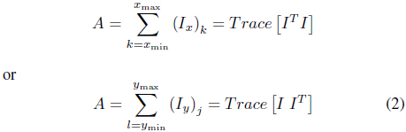
Several parameters such as object window, object area, and expansion and contraction parameter defined in are reintroduced in this paper. The binary image is denoted by

where

The center position
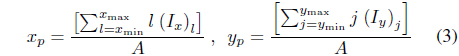
where
In case of object tracking with a video stream, the size of the target object changes according to its distance from the camera. Thus, the size of the object window must be changed depending on the size of the target object. To carry out this operation, the expansion and contraction parameter is defined as

which is the ratio of the object window to the target object. Note that the object window must include the target object, and
2.2 Separable, Partially Separable, and Inseparable Objects
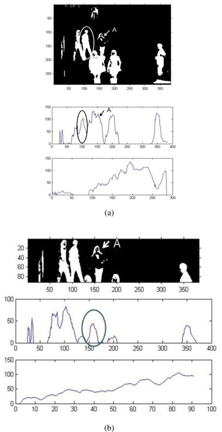
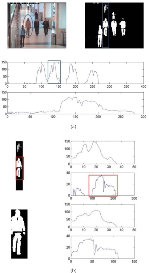
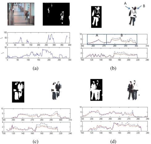
It is important to separate the target object from other objects, in order to ensure that the resulting object window contains only the target object. Figure1 shows a group of people walking together (left), and its corresponding
Even in this case, the target object lies between 100-220 pixels on the
Let us now consider another example where the aim is to separate the encircled image as shown in the top-left figure of Figure 2. As shown in the middle and bottom figures, the target object (people) is partially separable on the
The entire process of object tracking is described in this section. This section describes the overall system flow and suggests an algorithm for updating the background image. A method for expansion and contraction of the object window and the process of selecting an object by color information are also described in this section.
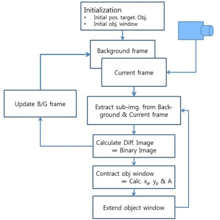
The overall process of object tracking is shown in Figure 3. The first step in object tracking is the initialization process. This step involves
Computation of the initial position of the target object, Selection of an extended initial object window, Selection of Δp0 (Δx0, Δy0), which is the initial value of the variation of the center of mass point of the target object, and Computation of the predicted center of mass position for the next frame.
Go to the first frame. Extracting the sub-image from the background frame and the current frame is the second step in this process. In this step, the predicted center of mass position is considered as the center and the size of the window is three or four times greater than that of the object window that was previously selected. In the next step, the absolute difference between the two sub-images obtained earlier is calculated and converted into a binary image using a thresh-old operation. The fourth step involves calculating diag(
The target tracking process described above can be summarized as three key-stages, prediction - operation - update. In prediction stage, the predicted center of mass position of the target objects are computed by using informations obtained previous frames, and expanded object window, centered at the predicted center of mass and sized three or four times larger than target object, is selected for each target. The primary role of operation stage is extraction of the target objects. This stage includes extraction of sub-image, conversion of sub-image into binary image, calculation of
3.2 Expansion and Contraction of ObjectWindow
The center of mass position


where,
For the (


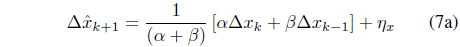
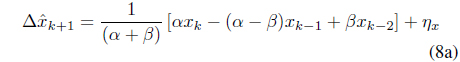
Eqs. (8a) and (8b) are described, in terms of measured values, as follows:


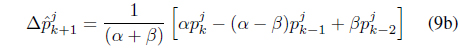
For the case of multiple-target tracking, the predicted position of the jth object is


The calculations used in this paper to predict the center of mass point of a target object are very simple and adequate for target tracking in an indoor environment. Of course, the Kalman filtering method or the particle filter algorithm is also available instead of Eq. (5).
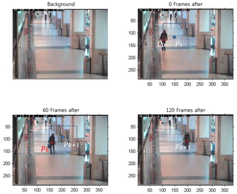
The expansion and contraction procedure, a part of the main result of this paper, is shown in Figures 4 and 5. For comparison with other studies, all video materials are borrowed from context aware vision using image-based active recognition (CAVIAR) [17]. Figure 4 shows how to extend and contract the object window. In this figure, the first image is the background image and the remaining three images show a woman walking at 60-frame intervals. The top-right image in this figure shows the expansion and contraction procedure of an object window. The first step is calculating
The operation of expansion and contraction of the object window is very simple as the actual operation is performed on the
The expansion and contraction parameter, (
3.3 Selection of Object by Color Information
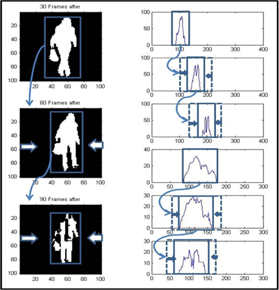
If an occlusion has occurred, then the color information of the target object just before and after the occlusion is very useful. The tracking can be successfully continued if the two objects are not identical or have similar color. The study on the occlusion can be divided into two kinds. The one is using color and shape information [15] and other is movement information of target object by using particle filer or Kalman filter algorithm [16, 20]. However, when both the objects have identical or similar colors, and are of similar shape, then the tracking may fail. Such a scenario requires further investigation.
In order to solve this problem, this paper uses both information, i.e., color and shape of the target object and velocity information. Figure 6 shows an occlusion (a and b) occurring just before (c) and after (d). The middle and the bottom figure of (a) is
4. Experimental Results and Discussion
To verify the validity of the algorithm presented in this paper, several experiments were performed using mobile images provided by CAVIAR [17]. The first experiment involved tracking one person walking from the bottom-right corner of the lobby towards the top left corner. The second experiment involved tracking two people walking in opposite directions and one person walking in a crowd. The last experimental scenario involves tracking three people walking together and another person walking in the opposite direction.
4.1 Scenario 1: Tracking One Person Walking in the Lobby
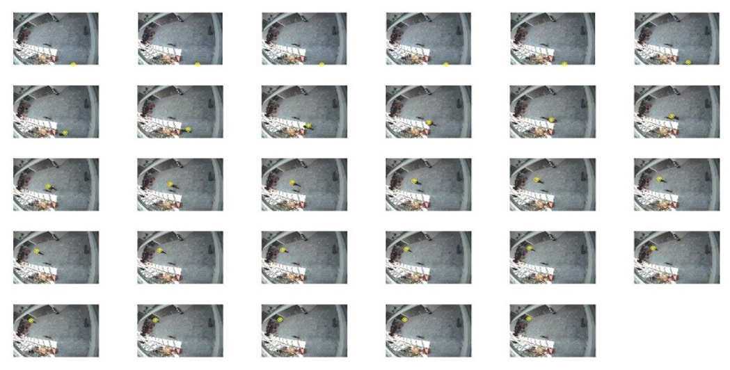
The first experiment involves tracking one person walking from the bottom right corner of the lobby towards the top left corner. The tracking results of this experiment are shown in Figure 7. Each frame in this figure is selected from the 10-frame steps. The calculated target positions for each frame are marked by “*”. As shown in Figure 7, the target tracking is performed successfully and the proposed algorithm works well.
4.2 Scenario 2: Tracking Two PeopleWalkingWith Other People
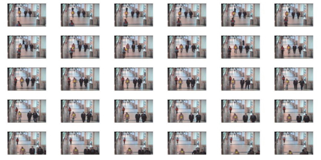
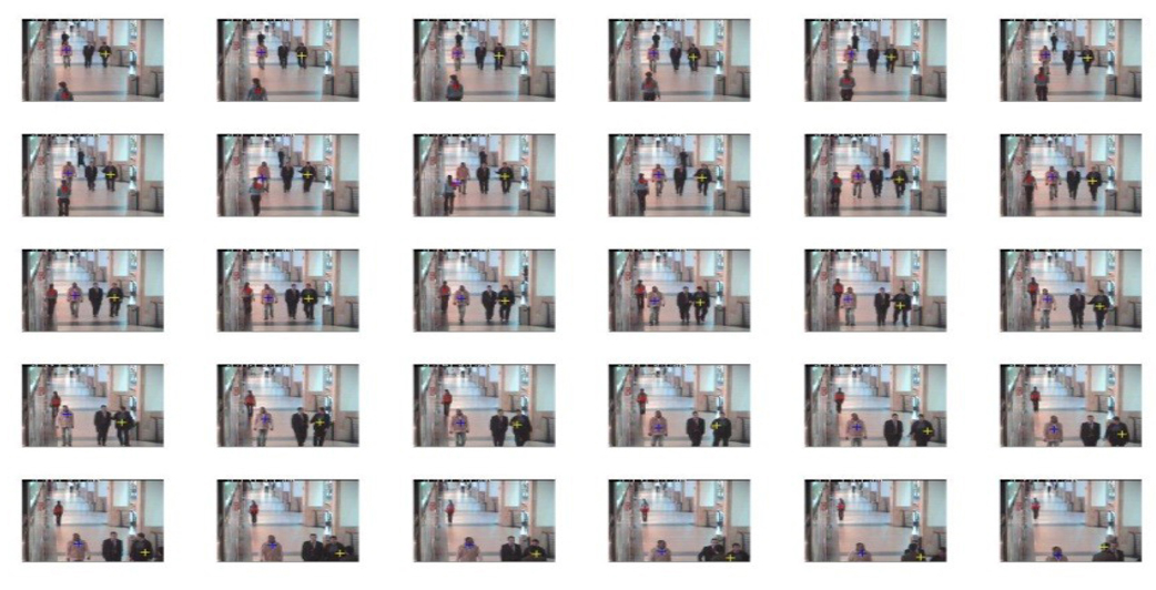
The second scenario consists of tracking two people walking in opposite directions and one person walking in a crowd. In Figure 8, the tracking procedure is shown by 13-frame intervals. In each image, the person walking in the upward direction is marked by a red cross. Further, the person walking with a group of three people from the center in the downward direction is marked by a yellow cross. As shown by the second row and fourth row, accurate tracking is performed even when these two people approach very closely.
4.3 Scenario 3: Tracking Three People Walking With Other People
The third experimental scenario is to track three people walking together and another person walking in the opposite direction. This scenario is the same as scenario 2, except that one person is added to the target. It is known by this scenario that the computational complexity increases in comparison with scenario 2. However, it does not significantly affect the run-time. This procedure is shown in Figure 9.
This paper investigated multi-human tracking in an indoor environment and presented a modified E-C method. The proposed algorithm provides the advantages of the mean-shift algorithm as well as the useful properties of particle swam optimization and filter-based algorithms for multi-object tracking. Some useful new variables were defined, such as object window, E-C parameter (i.e. the ratio of the object area to the object window area),
No potential conflict of interest relevant to this article was reported.