In a satellite communication, S-band antenna with its functions of telemetry, tracking, and command (TT&C) is an essential and fundamental component in monitoring and controlling the normal operation of satellite [1].
In general, a relatively low gain and wide beamwidth are required because communication should be available, even in the situations of changing altitude. Researchers have suggested several candidates for TT&C satellite antennas, including the microstrip patch [2], quadrifilar helix [3], conical spiral [4], and turnstile antenna [5-8]. The turnstile antenna, in particular, has several advantages, such as low complexity, easy fabrication, and robust characteristics with wide beamwidth.
This paper introduces a theoretical approach with equivalent model horizontal and vertical dipole elements. We validate our analysis by conducting mathematical manipulations and full-EM simulations using far-field approximations and the commercially available software CST Microwave Studio (CST MWS; Computer Simulation Technology AG., Darmstadt, Germany). In Section II, the equivalent model of the proposed antenna is dealt with using real dipole and image sources. The analysis of current distributions verified the relationship between the bowtie-shaped dipole and the wired dipole. In addition, a mathematical analysis of the modified dipole antennas is used to predict the electrical performances of the proposed antenna and compared them with the measured data of the fabricated antenna. A brief conclusion is provided in Section III.
II. EQUIVALENT MODEL OF RADIATORS
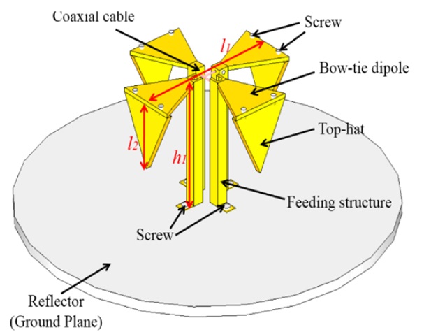
Fig. 1 shows the geometry of the previously proposed antenna with structural modification and an isoflux pattern of circular polarization. As shown in Fig. 1, the radiators are composed of top-hat loaded bowtie-shaped dipole antennas with two feeding structures. Circular polarization with a wide beamwidth is generated by launching a Wilkinson power divider, which has a 90° phase difference and wide impedance bandwidth, below the ground plane.
The vertical top-hat elements have been attached specifically to generate a radiation pattern in a direction close to the ground plane. As a candidate receiving antenna working for a TT&C satellite, it covers the frequency range from 2,025 to 2,125 MHz in the satellite communication system. The important aspects for the proposed antenna are the enhancement of the axial ratio beamwidth affected by the vertically installed top-hat elements and beamwidth expansion of the isoflux pattern.
2. Equivalent Model of Top-Hat Loaded Antenna
For the mathematical evaluations of E-field distributions and to simplify the understanding of the radiation mechanism of the proposed antenna, the bowtie-shaped dipole elements is defined and modeled as simplified crossed dipole elements.
Fig. 2 shows the equivalent model of the proposed and modified turnstile dipole radiating elements by assuming the infinite ground plane of
The current distributions on the real source dipole elements can be approximated for the evaluation of the far-field radiation patterns as following equations [9].
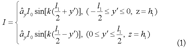
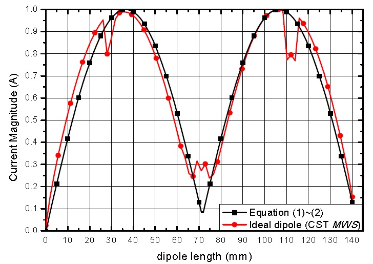
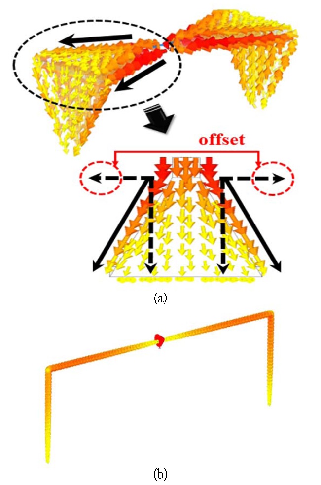
Fig. 3(a) shows the surface current distributions of the bowtieshaped dipole which is a radiator in the designed turnstile antenna. As shown in Fig. 3(a), the vector current flow (real lines) can be divided into two basis components (dashed lines) relative to the main horizontal axis of bowtie radiator. The two opposite directions may cancel each other, while the other components remain and may be added positively. Consequently, the effect of actual current distribution will approach that of the ideal dipole antennas shown in Fig. 3(b).
For the validation of the assumed current distributions, the normalized current distributions obtained from mathematical representations in this work and CST MWS have been compared in Fig. 4 and show good agreement with a small discrepancy. As shown in Fig. 4, some discrepancies are evident in the results at dipole lengths of less than 30 mm, around 70 mm, and more than 110 mm. It can be expected that the reason is due to the feeding point for horizontal dipole and discontinuities in the connections between vertical and horizontal elements. However, all three results using mathematical representations and CST simulation for two kinds of dipoles are nearly the same.
First of all, all the current distributions on the radiating elements without/with top-hat elements are assumed to be sinusoidal. The total radiated electric field can be obtained from the six components consisting of real source and image source effects (see Appendix).
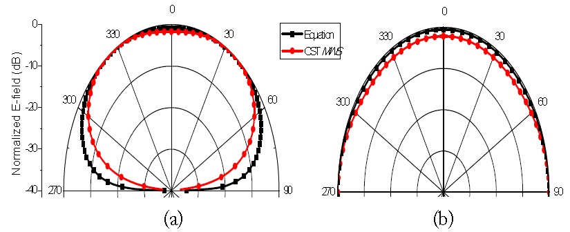
Eqs. (3) and (4) show the far-zone radiated field of horizontal dipoles without/with top-hat elements, respectively.
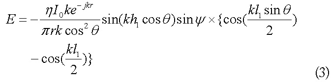
Fig. 5 shows the normalized radiation pattern when an ideal dipole without/with top-hat loaded elements are considered. As predicted from Fig. 5(a) and (b), the entire radiation pattern becomes broader, which means that radiation in the direction of 90° can be generated as the additionally vertical elements is attached. Hence, the enhancement of beamwidth can be accomplished because of the effects of the attached vertical dipoles.
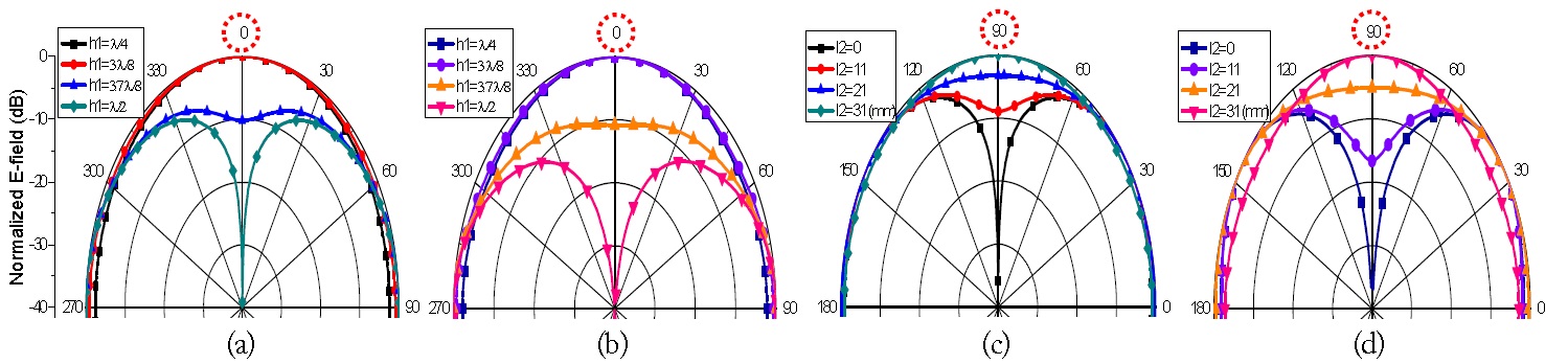
In order to analytically investigate the change of the radiation pattern according to the length of top-hat loaded radiating elements and isoflux radiation pattern for covering all the target area uniformly, the proposed antenna is assumed to be installed on the PEC ground with an ideally infinite area. As shown in Fig. 6, it can be estimated from the mathematical representations using equivalent model and commercially available software based on EM full simulation that the radiation pattern could be changed by adjusting the height and the length of the top-hat radiating elements.
Fig. 6(a) and (b) show that the usage of a quarter wavelength in the distance between the ground plane and horizontal dipole elements results in the pattern of broadside direction perpendicular to the horizontal dipole elements. However, as the height increases, the gain in the broadside direction parallel to
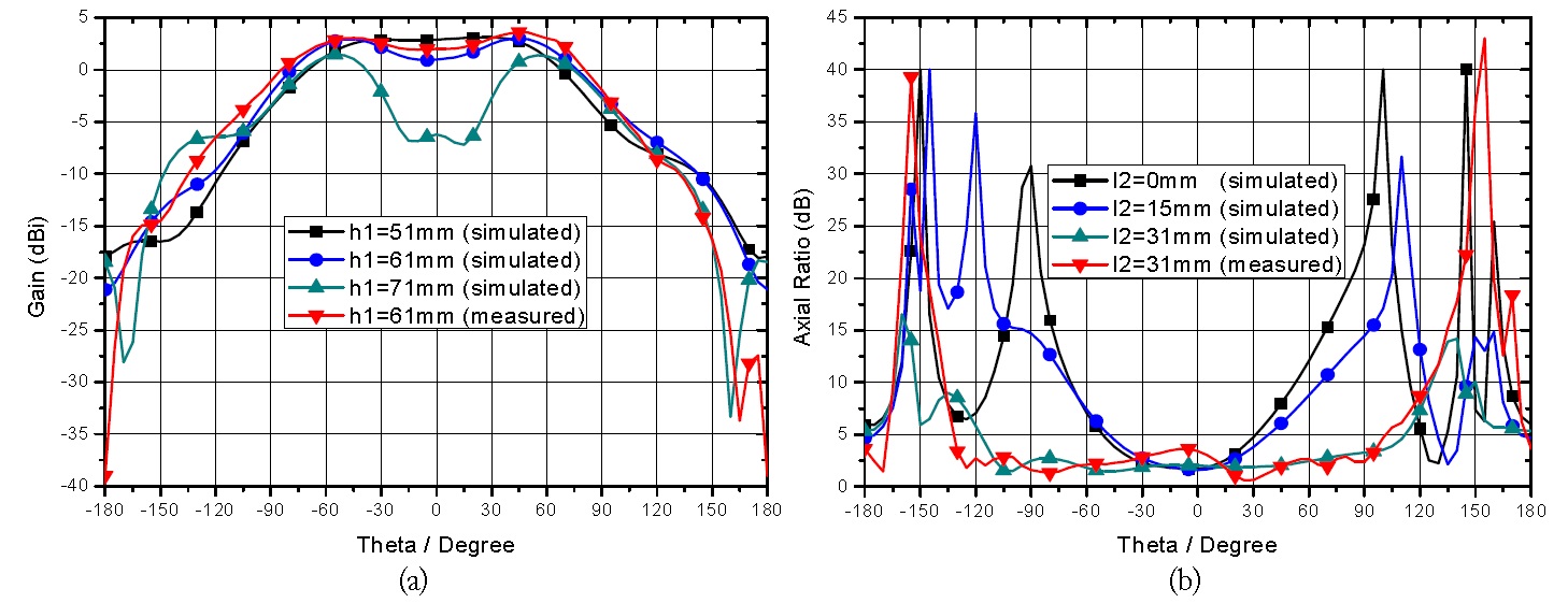
For the gain and axial ratios of the proposed and modified turnstile antenna, simulations and measurements were carried out with the parameter values of
An equivalent model of a top-hat loaded turnstile antenna has been developed by applying an image method and investigating current distributions on the radiating elements. The ideal dipole antennas and the proposed antenna were compared using the radiation pattern. A wide AR beamwidth was achieved with an isoflux pattern. It is ensured that the proposed equivalent model analysis can be effective for rapid design in terms of the radiation pattern and axial ratio in satellite communication.

![The radiator part of S-band turnstile antenna [8].](http://oak.go.kr/repository/journal/13748/E1ELAT_2014_v14n3_278_f0001.jpg)