The space programmes of several countries have established themselves as reliable and excellent service providers worldwide in the fields of remote sensing, communications, weather forecasting, satellite education, telemedicine, etc., by launching commercial satellites. The Indian space programme is among those who have also established themselves as service providers using polar satellite launch vehicles and geosynchronous satellite launch vehicles. Presently, the cost of space exploration by the Indian Space Research Organization (ISRO) is relatively low as compared with other space agencies. However, ISRO is endeavoring to further lower the cost of space exploration, so that space services can be delivered to every last person on the planet.
Various systems play key roles in controlling the cost of space exploration [1]. Materials are pivotal to the costs of almost all systems. Hence, the goal of reducing costs can't be achieved without developing advanced materials. The development of a new class of lighter and cheaper materials whose performance can match that of existing materials is the need of the hour. Composites are the most promising materials in this category [2]. They are lighter, cheaper and can be tailored to meet specified requirements. Various types of composite are already being used for space applications [3-7]. One of these is the class of carbon/silicon carbide composites (C/SiC composites).
C/SiC composites possess an excellent set of properties including strength, stiffness, oxidation resistance, creep resistance and chemical stability. Additionally, they have low density and low wear [8]. Since they retain most of their properties at elevated temperature, they can be used for high temperature applications. Further, their excellent set of thermo-structural properties coupled with low density make them the best candidate for aerospace applications such as wing leading edges, etc. [9]. Additionally, they have important applications in the field of high temperature sensors, optoelectronics and brake discs [6,10].
A good amount of work has been done on various aspects of C/SiC composites. However, much of the focus to date has been on fabrication routes and techniques. Among these routes and techniques, continuous carbon fiber (CF) reinforced SiC matrix composites have occupied the centre stage [11-14]. In the last couple of years, short fiber reinforced composites have attracted the attention of material scientists and designers due to several advantages. Mainly, the use of short fibers as reinforcement is a way to reduce the cost of the composites. The short fiber reinforced composites are increasingly used in a wide range of applications because of their easy adaptability to conventional manufacturing techniques and ease of fabrication [15-19].
In a short CF reinforced SiC matrix composite system, the properties of the composites can also be tailored to a large extent, as required. This tailorability and the end properties of short CF reinforced C/SiC composites depend upon various parameters. These parameters include the distribution of the CFs in the SiC matrix and the average particle size (APS) of the charge (CFs and powdered SiC). The agglomeration-free distribution of CFs in the SiC matrix also plays a key role in interphase bonding, crack propagation, mode of failure, etc. The particle size of the starting materials has long been recognized as a key factor in the end properties of a material. Further, the packing density increases with decreasing particle size. Achieving agglomeration-free distribution of CFs in SiC powder and controlling APS are both very complex due to differences in the nature and density of CFs and SiC.
Although a good amount of work has been accomplished with C/SiC composites by varying processing conditions, sintering aids and the ratio of reinforcement to matrix [15-19], not much attention has been given to the dispersion and distribution of short fibers in ceramic powders. Some work has been reported on the dispersion of CFs in SiC powder, but such attempts have been made using dispersing agents. According to reports by various researchers, the usage of such agents can disperse the CFs in SiC to some extent, but the lengthy cycle of processing yielded damage to the CFs' surface [20]. Hence, the emergence of newer methods and techniques for the dispersion of CFs in SiC powder will be a milestone in advancing the adoption of short CF reinforced SiC composites.
Along that line, we have explored a methodology involving the exfoliation of CFs prior to ball milling. To the best of the authors' knowledge, no work has previously been reported on the agglomeration-free dispersion and distribution of CFs in SiC powder using the concept of exfoliation of CFs prior to ball milling. Additionally, the mechanism behind fiber size reduction and splitting has not yet been reported. In our study, efforts were made to establish an effective and rapid method for the milling and dispersion of CFs in SiC powder by employing exfoliated CFs along with SiC powder in wet milling. This paper reports the rapid and effective fiber dispersing method and its mechanisms.
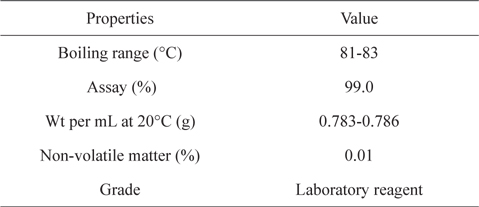
Polyacrylonitrile (PAN) based CFs (T-300, 3K; Torayca Co., Japan) and SiC powder (7.361 μm APS, α-grade) were taken for the milling experiments. Isopropyl alcohol (IPA) was employed as a slurry media for the wet milling of CFs and SiC powder. The properties of the raw materials are summarized in Tables 1-3. The designation of the samples processed under different processing conditions is given in Table 4.
[Table 1.] Properties of carbon fibers
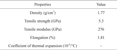
Properties of carbon fibers
[Table 2.] Properties of isopropyl alcohol

Properties of isopropyl alcohol
[Table 3.] Properties of SiC powder
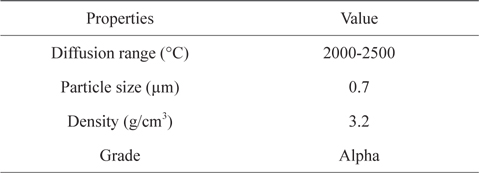
Properties of SiC powder
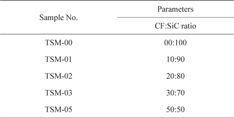
Sample designation
The continuous CFs from a fiber spool were chopped into discrete lengths using in-house designed and developed fiber milling equipment (Fig. 1)and a method of un-interrupted fiber milling. Discrete CFs of 3 mm length were obtained using this fiber milling equipment.
The chopped CFs of 3 mm length obtained from the fiber milling equipment were ground using a domestic mixer-grinder (Sumit). Grinding is basically a size reduction operation. It employs an attrition and impact mechanism to reduce the size of solids/powders. Attrition means reduction in size by rubbing against the solid jar's wall, blades, etc. Impact means reduction in size by direct hitting of the solid blades on the surface of the material which is to be reduced. The latter mechanism was found to be prominent in the grinding of CFs for exfoliation. The grinding was done for a total of 4 min in 16 cycles of 15 s each.
A ball mill (Fritsch, Pulversette P5 model) was employed for the milling study. Bowls (SS with an inner coating of silicon-nitride) of size Ø 74.5 × 70 mm, and balls (small balls of Ø 10 mm and big balls of Ø 20 mm) were used for this operation. The balls were also silicon-nitride. Milling is basically a size reduction operation like grinding. Unlike grinding, it is used to produce a very fine particle size. The ground exfoliated CF tows were dispersed in IPA (20 mL per 1 cm3 of charge) with SiC powder. The powder mixtures were milled for 4 h in 8 cycles (30 min operation per cycle) with a soaking time of 5 min after each cycle. The main objective of giving residence time in between cycles was to minimize heat generated during milling and to protect the material from any damage due to overheating.
An electric air oven (Thermosystem) capable of maximum heating up to 300℃ was used for the air-drying operation. The slurries of the samples were dried for 8 h at 90℃ @ 5℃/min. The drying operation was basically carried out to evaporate IPA from the slurry of CFs and SiC.
After air drying, the powder mixtures were found to have certain agglomerates. To break down these agglomerates to a finer scale, the powder mixtures were crushed using a domestic mixer-grinder in 4 cycles. In each cycle, crushing was carried out for 15 s in pulse form to avoid wear on the blades due to the SiC powder.
After the crushing operation, the powders of all the samples were characterized to determine the dispersion of the CFs and their distribution in the SiC powder. The microstructure analysis of samples was carried out using a Carl Zeiss SMT EVO 50 model scanning electron microscope (SEM). SEM images were taken under variable pressure using 80 P air pressure. Filament of LaB6 was employed for taking the images.
The APS (volume weighted mean) of all the samples after the crushing operation was characterized using size analyser (Mastersizer 2000 Ver. 5.22) from Malvern Instrument Ltd., UK. The APS was checked after completing all the operations of size reduction, exfoliation, dispersion, drying, and flocculation removal.
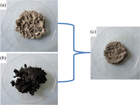
As milling and dispersion play an important role in the end properties of C/SiC composites made by the sintering route, a study comprised of chopping, grinding, milling, air drying and crushing was carried out to prepare and disperse the CFs in SiC powder. Continuous CFs from a fiber spool (Fig. 2a) were chopped using in-house developed equipment and technology into discrete 3 mm lengths (Fig. 2b). Using fiber milling equipment the CFs were chopped into a higher aspect ratio; this was intended to speed up the process of charge preparation, as the chopping of CFs into short lengths typically takes enormous time. The chopped CFs were then further ground using a mixer-grinder. During the grinding operation, the size of the CFs was reduced from 3 mm to approximately 1 mm. The size of the CFs was certified by visual inspection and manual measurement. Further grinding resulted in quite good exfoliation of CF tows. A digital image of exfoliated ground CF tows is depicted in Fig. 2c.
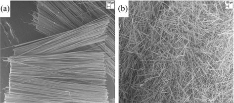
A microscopic analysis of the effectiveness of CFs exfoliation using the mixer-grinder was done by taking SEM micrographs of un-exfoliated tows and exfoliated tows. The SEM images of the chopped CF tows and exfoliated CFs are shown in Fig. 3. From Figs. 3a and b, it can be clearly seen that the bunch of filaments bound in a single discrete tow has been exfoliated. The exfoliated CF tows (Fig. 4b) and SiC powder (Fig. 4a) were further ball milled using IPA as slurry media. The powder mixture obtained after ball milling, drying and crushing of CFs and SiC powder is depicted in Fig. 4c. It can be seen from Fig. 4c that the CFs are dispersed uniformly in the SiC powder. The microscopic analysis of the dispersion of CFs in SiC powder is addressed in later paragraphs.
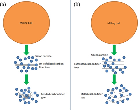
The main motive for exfoliating the chopped fiber tows prior to ball milling was to further reduce the length of the CFs at a faster rate than conventional methods, and also to aid in the uniform dispersion of CFs in SiC powder. Because the exfoliated CF tows allowed SiC powder to go in between the individual filaments as soon as the ball milling operation was started, the milling was quite easy and rapid. The probable mechanism behind the effect of exfoliation on the milling and dispersion of CFs in SiC powder was conceptualized. The conceptual arrangement of this phenomenon is depicted in Fig. 5.
From Figs. 5a and b, it can be seen that the fine particles of SiC are unable to go in between filaments of an un-exfoliated tow because of the very tiny gap available between the filaments. Hence, the impact delivered by the milling ball can’t break the filaments. This may result in a bended tow as shown in Fig. 5a. On the other hand, the fine particles of SiC can enter in between filaments of an exfoliated tow as depicted in Fig. 5b. As the particles of SiC are harder than the carbon filaments, milling of the carbon filaments will take place when they are impacted by the milling ball (Fig. 5b). Additionally, the exfoliation of the CF tows aided in the fine dispersion (Fig. 6) of CFs in the SiC powder. Further, the usage of the grinding operation for the exfoliation and shortening of CF tows resulted in an enormous reduction in milling and dispersion time. Excellent dispersion (Fig. 6) and milling of CFs in SiC powder was achieved in 4 h of ball milling, whereas Hao et al. [20] study of the dispersion of CFs in SiC powder using dispersing agents involved a very long duration (48-72 h). Further, even with dispersing agents and after prolonged milling, they could disperse only 30 vol% of CFs in SiC powder, whereas we could disperse up to 50 vol% of CFs in SiC powder.
Additionally, as is evident from Fig. 6, dispersion of the CFs in SiC powder was achieved without damaging the surface of CFs, whereas damage to CFs’ surface was reported by Hao et al. [20]. The main cause behind that damage was the prolonged milling they carried out [20] whereas we could disperse CFs in a short span of time by incorporating the exfoliation step, which aided in achieving excellent dispersion without damaging the CFs’ surface.
Further, from Fig. 6, it can be seen that not even one single spot is visible where two or more CF filaments are stacked together axially. This shows that there was excellent dispersion of CFs in SiC powder for all vol% of CFs.
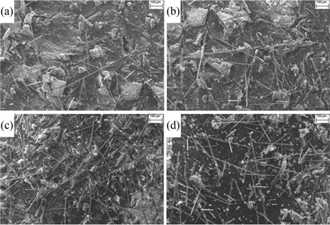
Though distribution of the CFs is also quite good, the results are not similar to dispersion. It can also be seen from Fig. 6, that the distribution is extremely uniform for 10 and 20 vol% of CFs, whereas it is moderately good for 30 and 50 vol% of CFs. This indicates the dependency of distribution on the loading of CFs. The loading of 20 vol% for CFs is very critical as far as distribution is concerned for this particular set of parameters. This might have happened due to the tendency of CFs to agglomerate at higher vol%, which would have led to the formation of some pocket zones, as depicted in Figs. 6c and d, of slightly higher concentration of CFs.
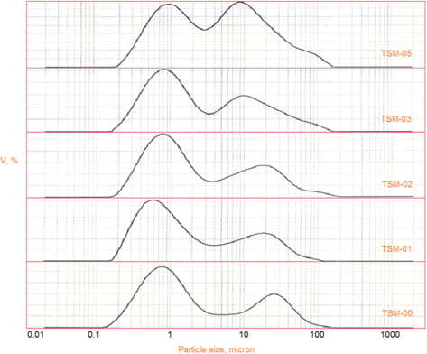
The APS of CFs and SiC ball milled powders was measured. Ground exfoliated CFs of approximately 1 mm got reduced to APS in the range of 9.5 to 11.7 μm depending upon the vol% of CFs in the SiC powder. The APS of all the samples is summarized in Table 5. The particle size distribution of CFs in SiC powder, for all the samples, is clubbed and presented in Fig. 7. As can be seen from Table 5, the APS of TSM-01, TSM-02, and TSM-03 increases linearly with CFs loading, whereas for TSM- 05, the increase in APS is very sharp. However, the APS has increased for all CFs loadings.
[Table 5.] Average particle size of powder samples
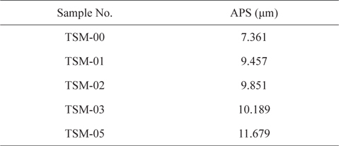
Average particle size of powder samples
A similar trend is shown by the particle size distribution of the composite mixtures. As is evident from Fig. 7, the sharpness of the second peak, which reflects the presence and milling efficiency of CFs, diminishes as the loading of CFs is increased from 0 to 10 vol%, and this trend continues till the loading reaches 30 vol%. This peak becomes extremely broad and tall as the loading increases from 30 to 50 vol%. This might have happened either due to the difference between the sizes of the CFs and SiC powder, or the poor milling of CFs in SiC powder. Regarding the first cause, as we increased the vol% of particles with higher APS in a mixture of lower ones, the APS of the resultant mixture went up. It can be seen from Table 5 that the APS has increased enormously, from 7.361 to 9.457 μm, or 28.47%, as the loading of CFs increased from 0 to 10 vol%. This resulted purely from the addition of particles of higher APS into those of lower APS.
Unlike that situation, however, the increase in APS is marginal, i.e. 4.17%, when the CFs loading is increased from 10 to 20 vol%. Similarly, the increase in APS is very low, i.e. 3.43%, when CFs loading is increased from 20 to 30 vol%. This implies that the increase in APS is mainly dominated by the addition of higher APS particles into that of lower APS, which increases the APS of the resultant mixture.
However, this trend is different in the case of sample TSM-05. The increase in APS is appreciable, i.e. 14.62%, as CFs loading is increased from 30 to 50 vol%. This implies that in addition to increases resulting from the addition of higher APS particles to lower APS, which increases the APS of the resultant mixture, the APS is also controlled by something else. This other phenomenon might be poor milling, i.e. the shortening of CFs’ length, resulting in the higher APS of the resultant mixture at higher loading of CFs in SiC powder. The poor milling of CFs in composite mixtures could have occurred as a result of increased loading of CFs, which would have resulted in a reduction in the number of hits per unit fiber filament from the milling balls. In addition, it is well known that during ball milling, size reduction is mainly caused by attrition and compression, and both of these size reduction mechanisms depend upon the number of ball hits received by the solid particles to be milled. In the same period of time, the number of hits per filament will decrease when there are increasing numbers of CF filaments in the powder, resulting in less effective milling.
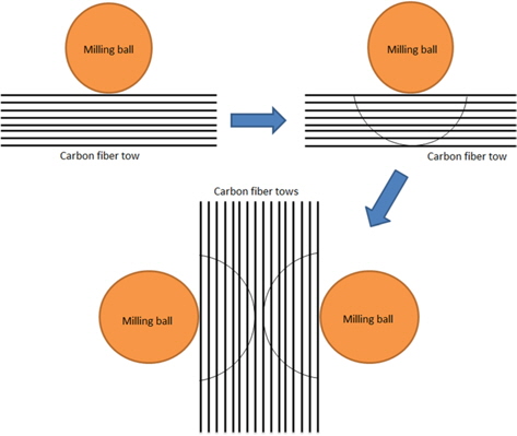
This can be easily understood with the help of Figs. 8-10. Figs. 8a and b represent the stationary arrangement of short CF filaments, SiC powder and milling balls for low and high vol% of CFs, respectively. As we can see from Figs. 8a and b, at lower vol% of CFs, each filament can receive a higher number of direct hits from the milling balls, whereas at higher vol% of CFs each filament will receive fewer direct hits from the milling balls, resulting in poorer milling of the CF filaments at higher vol% of CFs in the SiC powder.
Also, during the milling operation some of the exfoliated CFs would have come close to each other. This closeness would have been more frequent for the samples with higher CFs loading than for those with lower CFs loading. Due to the increased closeness of the CFs, the interior filaments as depicted in Fig. 9 would have been shielded, and not have experienced the direct impact of the milling ball, whereas in the case of less CFs closeness, the interior filaments as depicted in Fig. 10 would have experienced the hit by the milling ball. As a result of the occurrence of this phenomenon, the milling of CFs in SiC powder would have been poorer, which resulted in higher APS for TSM-05 with 50 vol% CFs loading.
A novel methodology for the dispersion of CFs in SiC powder without any dispersing agent was established and demonstrated successfully. The probable mechanism behind the rapid and effective dispersion of CFs, resulting from the inclusion of an exfoliation step in the method, was conceptualized and explained. The method's rapid dispersion of CFs in SiC powder was found to be very promising for obtaining damage free CF reinforced SiC composite mixtures. Further results on the influence of various ball milling and exfoliation parameters on the dispersion of CFs in SiC powder will be reported later.