Inrush current is a serious problem that plagues almost every item of electrical equipment and electrical machinery, especially those that are inductive in nature such as transformers, switching power supplies and synchronous/induction motors. In transformer study, a phenomenon that engineers always encounter, is that the amount of produced inrush current can be very large, many times larger than the transformer full-load current rating. Inrush current can produce mechanical stress to the transformer, damaging the transformer windings. It often affects the power system quality, may disrupt the operation of sensitive electrical loads due to voltage dips, and sometimes maloperation cases of transformer protection relays also happen. Therefore, it is a very serious problem that has to be tackled by electrical engineers worldwide [1,2].
There are a few methods that are used to protect transformers against inrush current. Most of these methods do not exactly eliminate inrush current, but they do reduce the current to a level that is safe for the equipment. A well-known method is a passive method which is done by using Negative Temperature Coefficient thermistors [3]. Controlled switching, and sequential phase energization are other methods to eliminate the inrush current caused by the transformer primary windings [4,5]. The simplified equation often used to calculate the peak value of the first cycle of inrush current in Amps is as follows:

where: V = Applied voltage in volts, L = Air core inductance of the transformer windings in ohms, BR = Remnant flux density of the transformer core in Tesla, BS = Saturation flux density of the core material in Tesla, and BN = Normal rated flux density of the transformer core in Tesla [6]. As the equation shows the applied voltage V is an effective part of the formula and its magnitude will change the amount of inrush current remarkably.
In this paper, a voltage ramping up method to gradually increase the transformer primary voltage is suggested. In a transformer circuit, the voltage and the current waveform are 90° apart from each other, the transformer current and flux are normally in phase so that the voltage and flux are 90° apart as well. With the point-on-wave device closing on the supply voltage, energizing a transformer does not result in core saturation, where; a small increase of flux may lead to a large increase in current [4]. Therefore, minimizing the flux will minimize the inrush current. The gradual increase of supply voltage is injected at 90° on the voltage wave, in order to reduce the amount of inrush current caused by the transformer primary side, at the time of energization.
In a transformer, the produced inrush current may last for about 10 cycles. In a 50 Hz system, the 10 cycles will take only 200 milliseconds. In order to have maximum efficiency of a transformer in service, the control of voltage waveform after the first 10 cycles is not necessary and is not required by the transformer; therefore the full supply voltage should be connected to the transformer primary windings after the mentioned 10 cycles. The control voltage should be done at the peak voltage waveform of 90°, in order to reduce the inrush current at the time of starting only, and only once. Thus a switching system to connect the normal rated voltage to the transformer circuit might be very efficient. This is the main point to designing a new switching controller with the help of a microcontroller.
The gradual increase of supply voltage is injected to the transformer primary in a few cycles, until the full amount of the transformer rated voltage is connected. By the help of power electronic components and a microcontroller, the method works such that a percentage of the supply voltage is firstly injected to the primary of the transformer, then; the amount of the injected voltage is gradually increased to the full voltage value after a maximum of 20 cycles or 1,000 msec time period, counted in 50 Hz supply. The microcontroller is assisted by a zero-crossing detecting circuit, to synchronise switching times, and sending pulses to the power electronic elements, the triacs/ SCRs, capable of switching on/off the main supply voltage to the transformer load. Initial switching tests, and simulations by software NI Multisim have been successfully done, to help the experimental research. The suggested method is generally more expensive, and is complicated, due to the usage of active components.
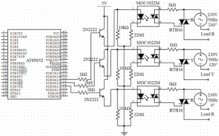
This work implements an 8052-based microcontroller, to trigger three power electronics elements triacs/SCRs, as switches to turn on a three-phase transformer. The high voltage section of the three-phase power supply is isolated from the low voltage microcontroller circuitry by optocouplers, and a zero-crossing detector works in tandem with the microcontroller, to synchronise the switching of the triacs/SCRs, so that the timing and triggering of the voltage ramping is coordinated [7,8]. The microcontroller is entirely programmed in assembly, with the MCS-51 Assembly Language [9]. Figure 1 shows the circuit of the microcontroller, and the basic components required for the work, provided by NI Multisim 11.0 software.
2. INITIAL TESTING AND TRIGGERING
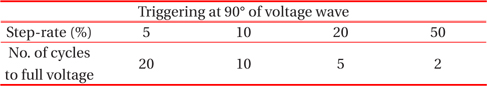
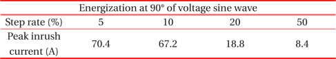
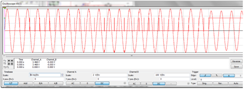
The zero-crossing detector circuit sends pulses for the positive and negative zero-crossings to the microcontroller. The microcontroller then reads these pulses, and it will wait for the last negative zero-crossing and trigger the triacs on the next zerocrossing. For the triggering, of the three-phase supply voltage in this research work, a stage triggering method is employed. The method is to start triggering triacs from the zero-crossings happening at the angle of 90° on the waveform of the supply voltage, or when the first cycle of the waveform reaches its peak value. For this triggering method, step rates voltage of 5%, 10%, 20%, and 50% are applied. Table 1 shows information on the triggering on the voltage sine wave, and Fig. 2 shows the results of NI Multisim 11.0 simulation on a starting angle of 90° for single phase switching.
[Table 1.] Summary of triggering.

Summary of triggering.
For the 50 Hz supply voltage, one full cycle of the ac waveform takes 20 ms to be completed. Initially, the first phase of threephase(A-phase) is triggered by a certain time delay, according to the step-rate chosen. A 50% step-rate has a time delay of 10 ms, after the zero-crossing is detected. This 10 ms time delay is generated in the assembly programming, by using loops, which is a conventional, but effective way of generating a time delay. For the second phase (B-phase), an interrupt timer is set to count an interval of 6.667 ms after each triggering of the first phase, as the second phase lags the first phase by 120°, and it translates into 6.667 ms of real time to reach its peak point. For the third phase (C-phase), a similar method is used to trigger the supply voltage, but this time a different interrupt timer is utilised. The output voltages for all the step rates are observed from the microcontroller to the switching pulses to insure accurate switching control of the stepping ramping voltage for the three-phase transformer, before actual experiments of the inrush currents effects.
3. INRUSH CURRENT TESTS ON TRANSFORMERS
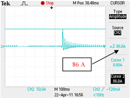
Inrush current tests were conducted with three single-phase 1-kVA transformers, which were connected in star to the primary. The inrush current effect tests were first conducted with direct on-line connection to the supply. This should serve as the initial value, to compare with the resulting inrush currents using the stepping ramping voltage control afterwards. A lot of trials were done, in order to get the highest possible inrush current resulting from the energization of the transformers at 0° of the supply voltage sine wave, and the existence of the maximum value of initial core fluxes, which is counted as the worst case of producing inrush current in the transformer [10].
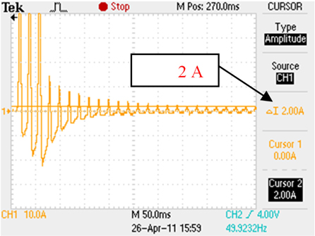
The highest inrush current for the primary star connected three-phase transformer 3×1 kVA rating was obtained to be 86 A, as shown in Fig. 3, and the steady state current of this transformer was found to be around 2 A, as it is shown in Fig. 4.
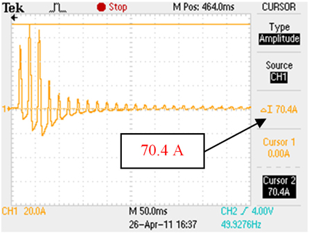
In the next step of the work, the microcontroller ramping voltage circuit was used, in order to reduce the magnitude of inrush current. After the series of tests were done, the followings are the results captured by the digital oscilloscope. For the step starting angle of 90° on voltage sine wave, and 5% step rate of ramping up voltage shown in Fig. 5, the inrush current was found to be peaking at 70.4 A. No significant inrush current suppression was observed from the inrush current previous value, of 86 A.
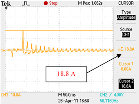
For the step starting angle of 90° on voltage sine wave and 20% step rate of ramping up voltage, the inrush current was found to have dropped to a 18.8 A peak. A significant suppression of inrush current was observed from the inrush current previous value of 86 A to the lower value of 18.8 A, as shown in Fig. 6.
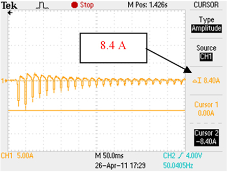
Lastly, as shown in Fig. 7 for the step starting angle of 90° on voltage sine wave, and 50% step rate of ramping up voltage, the amount of inrush current has also dropped to a 8.4 A peak.
At a glance, it seemed that the controlled triggering through the voltage ramping up technique is able to reduce the inrush current of a three-phase transformer load, up to certain extent. However, the reduction in the inrush current was not so significant, until at least the 20% step rate in 90° angle on the voltage sine wave. The control value of inrush current obtained peaked at 86 A, after many trials were done. Basing on the 86 A inrush current, a direct comparison was made with the results, which are shown in Table 2.

Reduction in inrush current with controlled triggering through ramping up voltage method (Initial record of maximum inrush current was 86 A).
The method of switching three-phase ramping up voltage is achievable by use of a microcontroller, and some standard electronics components such as triac/SCR, optocoupler and zerocrossing detector IC.
For transformers loads, the switching three-phase ramping up voltage can limit inrush current when the step rate is kept relatively high, that is, at a rate equal to or larger than 20%. Though the circuit has not been tested on an ac motor, another type of inductive load, it is believed that switching three-phase ramping voltage can effectively start an ac motor. In industries, ac motors need to be started by lower and controlled voltage, in order to reduce the staring current absorbed by the motor stator windings. This is due to the fact that the voltage is gradually increased until a very low starting current for the motor is observed. This is called a soft starter for the ac motor, and it is possible by the help of a microcontroller to gradually increase the supply voltage to the stator windings, in order to reduce the motor starting current. The circuit is deemed successful, for the fact that the switching of a three-phase transformer by voltage ramping is possible, with the help of a microcontroller circuit. In addition, the switching of the voltage supply can effectively limit the inrush current, when there is no failure in triggering.