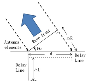
The future of wireless technology lies in wide bandwidth applications. However, the multipath fading due to increase of bandwidth degrades the system performance. And the increase of the carrier frequency incurs the reduction of transmission distance. After the third-generation system, there have been attempts to apply the phased-array antenna (PAA) to solve the problems mentioned [1]. A phasedarray antenna consists of individual antenna elements arranged in a two-dimensional plane or a line. Through individually adjusting the phase of the antenna elements without mechanical rotation of the antenna, the direction of beam emitted from the antenna can be changed. A smart antenna system has outstanding advantages, such as high-speed beam scanning ability, accurate beam pointing and the formability of the radiation beam. In detail, radiation beam can be formed by controlling phase between the antenna elements; and the amplitudes of current in the radar systems, satellite communications and mobile communications.
Various optical beam-forming concepts have been previously reported [2-8]. The techniques other than these are based on optical phase shifters [9], switchable delay matrices [10-14], liquid crystal polarization switching devices [15], a combination of a wavelength-tunable laser and a dispersive optical element, such as a high dispersion fiber [16, 17], a fiber optic prism [18, 19], a fiber Bragg gratings (FBGs) prism [20-22], or chirped FBGs [23-27].
In this paper, we have proposed an optical true-time delay beam-forming using a tunable DCM that consists of two tunable etalons as the dispersive optical element, and a multiwavelength fiber ring laser for phased array antenna. The time-delay difference between wavelengths, which is assigned for each antenna element, originates from wavelength dependence of the time delay in DCM. The proposed true time-delays (TTD) for transmitting and receiving have been implemented. And the characteristics of TTD are measured and discussed.
II. ARRAY FACTOR OF PHASED-ARRAY ANTENNA
When the array spacing is uniform in a phased-array antenna, the normalized AF (array factor) is
In Eq. (1),
The electrical current which is supplied to the
where An and αn are the amplitude and phase of the current, respectively, and τn is group delay of the n-th antenna element. Substituting Eq. (2)-(4) into Eq. (1), the normalized AF can be obtained to be
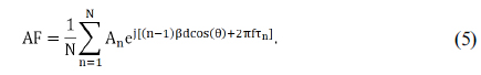
From Eq. (5), we can see that TTD technology controls a radiation angle of the beam by changing the time delay.
III. OPERATION OF PHOTONIC TRUE-TIME DELAY
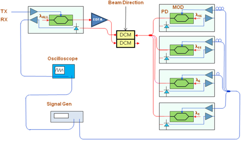
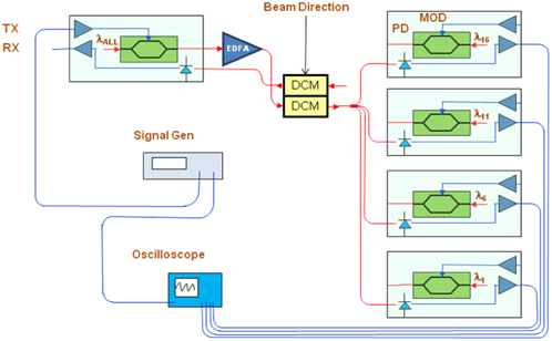
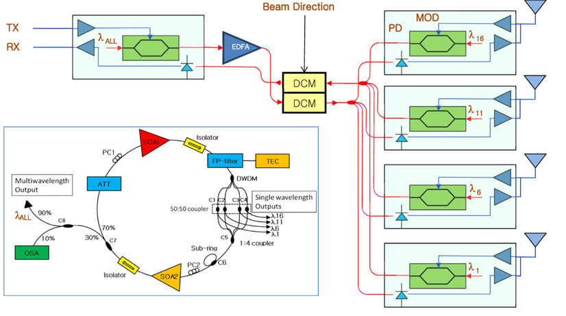
The single-beam PAA for transmitting and receiving proposed in this paper is shown in Fig. 2. The PAA system consists of five O/E (optical to electrical) and E/O (electrical to optical) converters, a multiwavelength fiber ring laser and optical tunable DCMs. The O/E and E/O boards are used to convert between optical and electrical signals, because the optical TTD supports the microwave PAA system. The DCMs, which consists of temperature tuned etalon filters, are used to make the adjustable time delays of the transmitted and received signal.
3.1. Group Delay of Dispersion Compensating Module
When the optical-pulses are transmitted to a single mode optical fiber, the pulses will suffer an intra-modal dispersion. Dispersion can be classified into waveguide dispersion and material dispersion, which is a function of wavelength. Normally, FBG or dispersion compensating fiber (DCF) is used to compensate the optical fiber dispersion. The DCM based on DCF has nearly constant dispersion value according to the wavelength, so that the time delay is proportional to wavelength.
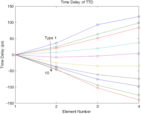
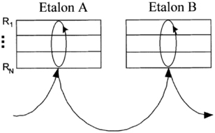
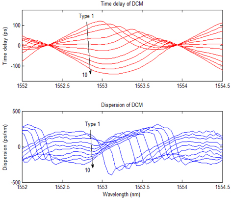
In this paper, the DCM board consists of a DCM and two thermo-electric cooler (TEC) controllers. The temperature controllers are used to adjust the value of dispersion of tunable DCM. Fabry-Perot etalon based DCM of JDS Uniphase is used to make time delays between the antenna elements. Schematic of tunable DCM is shown in Fig. 3 [28]. When the etalon A is designed to have a negative dispersion slope, the etalon B is designed to have a positive slope. The dispersion slope of etalons should be designed to have a simple ratio. The group delay can be controlled by adjusting the temperature of the etalons A and B. Figure 4 shows the time delays and dispersions of tunable DCM for ten types of dispersion tuning, changing the temperatures of the etalons as shown in Table. 1, which is measured by optical dispersion analyzer (Agilent 86038A). The time delay and the dispersion graph in Fig. 4 repeated with every 200 GHz in full C-band.
[TABLE 1.] Temperature of etalons A and B for 10 types of dispersion tuning [28]
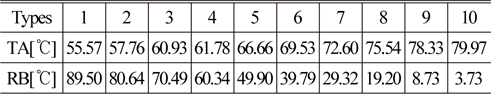
Temperature of etalons A and B for 10 types of dispersion tuning [28]
3.2. Multiwavelength Fiber Ring Laser
A multiwavelength erbium-doped fiber ring laser is used as an optical source of TTD, which has a multiwavelength output and four single wavelength outputs. The fiber ring laser consists of two SOAs, FP filter and DWDM. SOAs are used to compensate attenuations of the optical fiber, couplers and connectors in the laser ring. The DWDM and tunable FP filter are used to select lasing frequency of the fiber laser ring cavity. The frequency spacing of the fiber laser can be coarsely changed by choosing the DWDM channels, and then finely changed by adjusting the temperature of the FP filter.
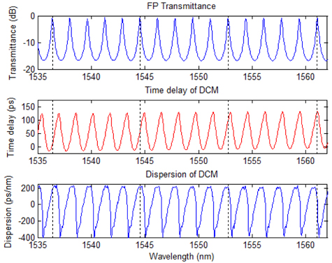
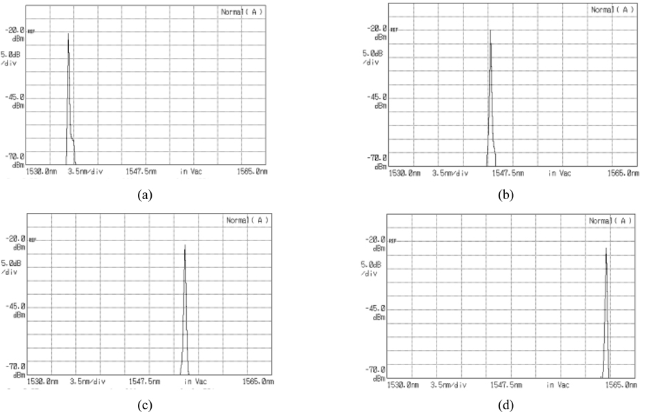
The transmittance of the FP filter is shown in Fig. 5(a) and the FSR of the FP filter was adjusted to ~ 207.6 GHz. The transmitted wavelengths are selected again by 200 GHz DWDM. In this experiment, the channel separation of commercial DCM and DWDM is 200 GHz. Wavelength λ1, λ6, λ11 and λ16 of DWDM are selected for four wavelength fiber laser oscillations, which have center wavelengths of 1536.61, 1544.53, 1552.52 and 1560.61 nm. Dotted lines in Fig. 5 show the lasing wavelengths of the fiber laser, which are 1536.4, 1544.5, 1552.8 and 1561.1 nm. These four wavelengths still remain within the bandwidth of the DWDM. The output powers of DWDM are divided by the 50:50 couplers and single-wavelength outputs are obtained. Optical spectrum analyzer (OSA), Anritsu MS9710B is used to measure the spectra of single wavelength outputs at λ1, λ6, λ11 and λ16, which are shown in Figs. 6(a), (b), (c) and (d), respectively. The separation of lasing wavelength can be coarsely changed by choosing another DWDM channel or by finely adjusting FSR of FP filter by temperature.
As we mentioned earlier, FSR of FP filter is slightly larger than the channel separation of the tunable DCM. Time delay and dispersion of the DCM at a dispersion tuning are shown in Fig. 5 (middle and lower). Time delays for the four of lasing wavelength (dotted line as shown in Fig. 5 (middle)) increased as the channel number at the dispersion tuning increased. These time delays can vary according to dispersion tuning and will be discussed later.
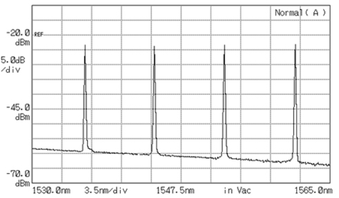
Figure 7 is a measured spectrum of multiwavelength output of the fiber ring laser by OSA. In addition, the ring structure noise amplified at the unwanted wavelengths can appear at the output, so the sub-ring configuration is used [29]. One output coupler that generates four wavelengths and four outputs that include single-wavelength in the fiber ring laser are used for data transmission and reception, respectively. Such a multiwavelength fiber ring laser structure was obtained and is advantageous since it can minimize the number of devices in the entire phased array antenna system.
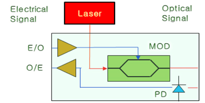
The E/O converter consists of an electro-optic modulator (EOM) and an EOM driver. O/E consists of the photo detector and low-noise amplifier (LNA). Schematic of the E/O and O/E converter board is shown in Fig. 8. The laser lights from one multiwavelengths output and four single-wavelength outputs of the fiber ring laser are used as the laser sources of E/O converter for transmitting and receiving, respectively. The pattern generator (Anritsu MP1763C) was used to generate the RF signal.
3.4. Optical True-Time Delay for Phased-Array Antenna System
The transmission signals of four-wavelengths emitted from the E/O converter-0 are amplified by erbium-doped fiber amplifier (EDFA) and delayed by DCM. Time delay and the dispersion of the DCM according to the temperature of the etalon are shown in Fig. 4. Since we set the FSR of the FP filter in the fiber ring laser slightly larger than the channel separation of DWDM, the time delay increased as the lasing line wavelength was increased, as shown in Fig. 5 (upper). The four single-wavelength outputs are demultiplexed by DWDM device and converted into electrical signals by O/E converters. The antenna elements will transmit the signals with corresponding time delays.
The signals received from the antenna elements are converted into optical signals by E/O converter-1 to 4. The DCM compensates the time delays that are caused by the direction of the electromagnetic wave. The output of the DCM which eliminated the time delays is converted to electrical signal by O/E converter 0.
IV. EXPERIMENTAL RESULTS OF TTD CHACTERISTICS AND DISCUSSION
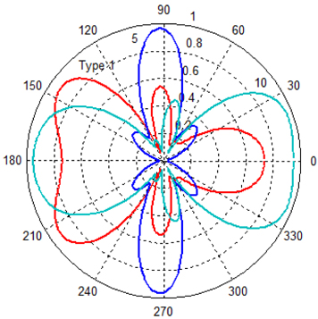
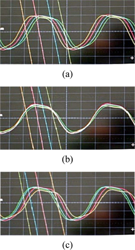
The experimental schematic for the time delay measurement of each antenna element is shown in Fig. 10. A signal generator and a 4-ch oscilloscope are used. The transmission signals at each antenna element have different time delay as shown in Fig. 11, which can be adjusted by changing the temperature of the FP filter. The antenna elements 1 to 4 correspond to green, blue, red and yellow, respectively. The antenna element 4 has ~ 140 ns shorter time delay than the element 1 as shown in Fig. 11(a) (Type 1 of dispersion tuning). Figure 11(b) shows that the elements have almost the same delay time (Type 5 of dispersion tuning). As shown in Fig. 11(c), the delay time of element 4 is ~ 100 ns longer than element 1 (Type 10 of dispersion tuning). The maximum delay between antenna elements should be ± 150 ps to be able to scan the angle from 0° to 180° in 10 GHz system. Figure 12 shows time delay of DCM according to temperature changes of etalon in DCM, which is obtained from the experiments of Fig. 10. The time delay is in the range of -140 to 117 ps. The radiation pattern that is obtained by simulation from the time delay of TTD in Fig. 12, is shown in Fig. 13. The radiation patterns are obtained from different types of dispersion tunings. We can see that the angles between the peak radiation direction and the antenna axis can be changed from 15 to 145°. Even if the attained rotation angle by peak radiation is not in the range of 0-180°, the radiation in the direction of 0 or 180° can be observed as shown in Fig. 13.
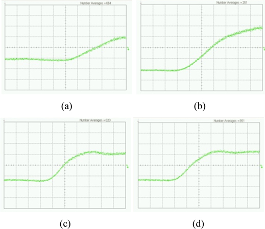
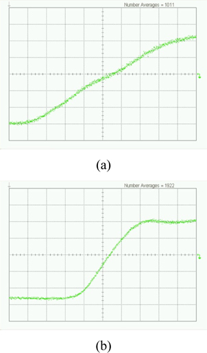
To investigate receiving characteristics of TTD, the elements of the antenna are substituted with a signal generator and the delay lines which simulate the direction of electromagnetic wave in our experiments, as shown in Fig. 14. The received signals from the elements 1 to 4 of antenna at the DCM input are shown in Fig. 15(a) to (d). The time delay of element 1 is 130 ps longer than that of element 4. The time delay of received signal from each antenna is due to the direction of the propagation. The time delays of the received signal between the elements should be compensated by adjusting the temperature of etalon in DCM, so that the steep slope of the waveform is maintained. The waveform of the DCM output (a) before and (b) after compensation of delay time, are shown in Fig. 16. The value of the compensated time delay corresponds to the direction of the electromagnetic wave. The direction will be used to respond to the received signal. The output of DCM is converted to electrical signal by O/E converter.
The optical true-time delay beam-forming system using a tunable DCM for DWDM and a multiwavelength fiber ring laser for phased array antenna is proposed. The tunable DCM which is based on temperature adjustable Fabry-Perot etalon is used. The FSR of FP filter in fiber laser is selected to have a slightly larger value than the channel separation of DCM, in order to have longer delay time at longer lasing wavelength than at shorter wavelength. In experimental work, DCM was used to obtain the radiation angle rotation by temperature tuning of DCM.
The use of multiwavelength ring laser with one four-wavelength output and four single-wavelength outputs can reduce the number of optical devices to design a TTD. As a result, a DCM can be used to obtain the radiation angle by tuning the dispersion of the DCM at the fixed wavelengths of the fiber ring laser in the proposed optical true-time delay. And the time delay can be adjusted by changing the dispersion of DCM for each RF application.


![Schematic of tunable DCM based on etalons [28].](http://oak.go.kr/repository/journal/13419/E1OSAB_2014_v18n4_406_f003.jpg)

![Temperature of etalons A and B for 10 types of dispersion tuning [28]](http://oak.go.kr/repository/journal/13419/E1OSAB_2014_v18n4_406_t001.jpg)