In the development of astronomical optics, space optics [1-3], and inertial confinement fusion, large-aperture optical systems have been widely used. With long production cycle and high cost, large-aperture interferometers cannot satisfy the advanced requirements for testing large optical elements. In 1982, Kim addressed this problem by developing the sub-aperture stitching method [4]. The core of this method is stitching together the measurements obtained from all of the sub-apertures to generate the full-aperture result. However, location errors are inevitable when using this method, so researchers use the overlapping areas between sub-apertures to compensate for the location errors [5-8]. The location errors include piston, tilt, defocus, clocking, and position errors. Piston, tilt, and defocus errors are easily compensated, and clocking errors are usually quite small, but position errors are not usually compensated well by algorithms. In most cases sub-aperture stitching interferometers have high positional accuracy, so the high-frequency components of measurements are the key factors when compensating for position errors. Therefore, we use an image sharpening algorithm to strengthen the high-frequency components of measurements. The basis of image sharpening is computing the approximate gradient of a measurement, so that the data may be stripped of many low-frequency components after image sharpening. However, the low-frequency components are helpful in avoiding local minima, and a sub-aperture stitching algorithm based on the least-squares method can easily become trapped at a local minimum if the image is sharpened. A different optimization algorithm should be used to solve this problem.
Some researchers have used particle swarm optimization to address this problem in image stitching [9]. Particle swarm optimization can be more reliable than the least-squares method for finding the globally optimal solution. Therefore, we utilize particle swarm optimization in our algorithm to calculate the position compensation. In Section II we introduce an existing iterative sub-aperture stitching algorithm based on the least-squares method, while in Section III we describe our modified sub-aperture stitching algorithm, which uses image sharpening and particle swarm optimization. In Section IV we present the results of simulations comparing the performance of the two algorithms, and in Section V we report experimental results that demonstrate the effectiveness of the proposed method. Section VI presents our conclusions.
II. ITERATIVE SUB-APERTURE STITCHING ALGORITHM BASED ON THE LEAST-SQUARES METHOD
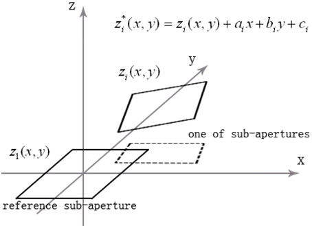
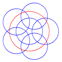
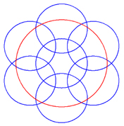
For convenience, in this article we discuss the testing of only plano-optical elements. First, a sub-aperture (usually the central one) is selected as the reference sub-aperture. Clearly the other sub-apertures have tilt and piston relative to the reference sub-aperture, as shown in Fig. 1. Thus it is necessary to compensate for the relative tilt and piston [5-7]:

where
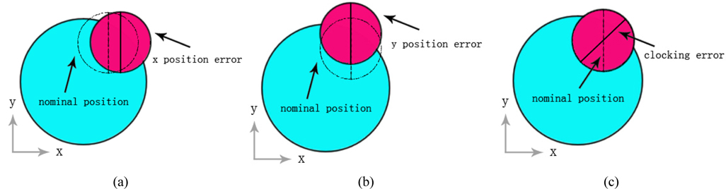
The sub-aperture stitching interferometer possesses six types of mechanical location errors, and the other errors must also be compensated. For the
where
Assuming that there are

Since linear approximation is used to solve the nonlinear problem described above, an iterative algorithm can be used [8]: alternately use overlapping sub-aperture areas to calculate compensation values, and use compensation values to calculate overlapping aperture areas.
Before discussing our algorithm, we provide brief descriptions of image sharpening and particle swarm optimization.
Image sharpening is a technique that reinforces the high-frequency components of images, and there are many different image sharpening algorithms [10, 11]. We use an image sharpening algorithm based on the Sobel operator [12], a famous gradient operator which is widely used in image processing.
Reference 13 states the following: “Particle swarm optimization is a computational intelligence-based technique that is not largely affected by the size and nonlinearity of the problem, and can converge to the optimal solution in many problems where most analytical methods fail to converge.”
In our algorithm we select the position value indicated by the instrument as the initial candidate solution, and the range of allowable errors is used as the search space for particle swarm optimization.
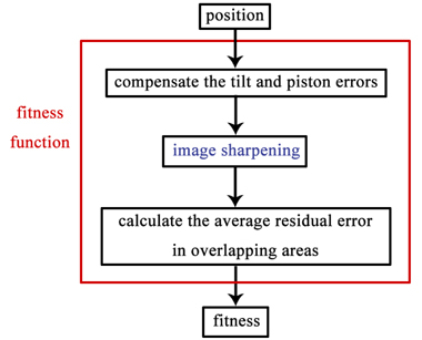
A flowchart of the process used to calculate the fitness of each particle is shown in Fig. 3. The least-squares method is used to compensate for the tilt and piston errors [5, 6], and the fitness is the average residual error in the overlapping areas. After clarifying the variables and fitness function, we use the particle swarm optimization algorithm to calculate the positions of the sub-apertures. After the positions of the sub-apertures have been determined, the stitching result can be calculated using the algorithm described by Otsubo et al. [6].
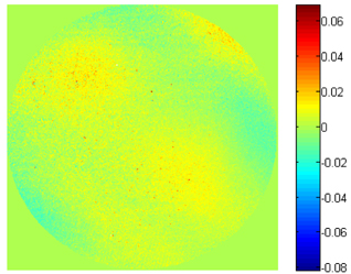
In the simulation, a measurement (301 × 301 pixels, as shown in Fig. 4) was divided into seven sub-apertures (Fig. 5), which were then stitched together using both the existing algorithm and our proposed algorithm.
After dividing the measured image into sub-apertures, we added random noise ([−0.0002, 0.0002] wavelength) and the piston, tilt, and position errors to each sub-aperture. The position errors were random lengths between −Width/2 and Width/2, where Width was a parameter used in the simulation.
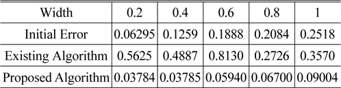
To evaluate the performance of the two algorithms with increasing values of position errors, the simulation results are compared in Table 1, where the initial error is the variance in the initial position errors. In the table the results for the existing and proposed algorithms show the variance in the position errors based on simulations using the respective algorithms. The existing algorithm could not compensate for position errors when Width was less than one pixel, whereas the proposed method performed quite well.
[TABLE 1.] Simulation results. All units are the length of one pixel

Simulation results. All units are the length of one pixel
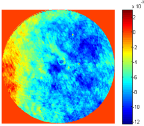
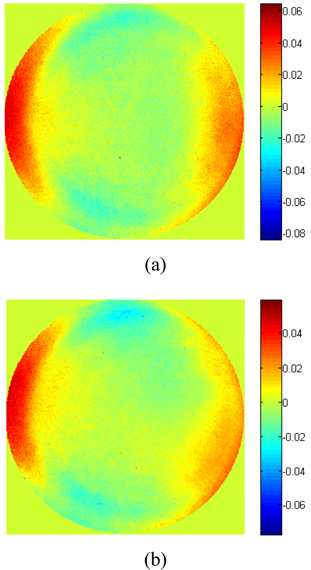
Using the layout of sub-apertures shown in Fig. 6, a flat surface (caliber = 150 mm) was measured with a sub-aperture stitching interferometer (caliber = 100 mm). The measurement results obtained with a full-aperture using our algorithm are shown in Fig. 7(a). For the measurement results obtained using an interferometer with a caliber of 150 mm (shown in Fig. 7(b)), the root mean squared error was 0.006372 λ and the residual error image is shown in Fig. 8.
In this study we proposed a modified sub-aperture stitching algorithm, which uses image sharpening algorithms and particle swarm optimization to improve the stitching accuracy for sub-aperture stitching interferometers with high positional accuracy. The results of simulations demonstrated that the proposed algorithm performs better than the existing method. A comparison with experimental full-aperture testing results demonstrated the validity of the proposed algorithm.