검색 전체 메뉴
PDF
맨 위로
OA 학술지
Experimental Study of Two-step Phase-shifting Digital Holography based on the Calculated Intensity of a Reference Wave
  • 비영리 CC BY-NC
  • 비영리 CC BY-NC
ABSTRACT
Experimental Study of Two-step Phase-shifting Digital Holography based on the Calculated Intensity of a Reference Wave
KEYWORD
Two-step phase-shifting digital holography , Phase-shifting interferometry , Computational imaging
  • I. INTRODUCTION

    Digital holography is a technique that permits digital capture of holograms and subsequent reconstruction of the original object on a digital computer. It is also a convenient form for data transmission and object recognition [1, 2]. The major advantages of digital holography, easy and highly sensitive recording of holograms and quick reconstruction, have been realized by rapidly developing CCD and computer technologies. Digital holography has been applied to microscopy [3-5], interferometry [6-7], image encryption [8, 9], and recognition of 3D objects [10, 11], and so on.

    In recent years, two-step phase-shifting digital holography has been used in optical image reconstruction because its requires fewer hologram recording [12, 13]. Tatsuki Taharae et.al experimentally demonstrated the parallel two-step phase-shifting digital holography which requires only the intensity distribution of the reference wave and spatial two phase-shifted holograms [14]. Jung-Ping Liu and Ting-Chung Poon adopted a correlation method to calculate the reference wave intensity [15]. These methods are more efficient than three or four-step phase-shifting holography, but they still need to record additionally the reference wave intensity or the object wave intensity. In this paper, we proposed an image reconstruction method with two-step quadrature phase-shifting digital holography, in which there is no need to record the reference wave intensity and the object wave intensity. In the system only two holograms are required to reconstruct the original object so it is more suitable for a real-time situation. We performed experiments to verify that our method can be used in 2D and 3D objects holography and there will not be convergence errors in CC calculation. We have applied this method well to holographic compressive imaging [16]. Section 2 introduced the principles of our method and Section 3 demonstrated the experimental results.

    II. FUNDAMENTAL PRINCIPLES

       2.1. Hologram Recording

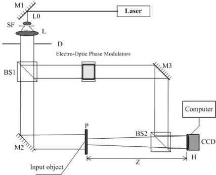
    A typical quadrature phase-shifting holographic setup is shown in Fig. 1., where a linearly polarized laser beam is expanded, collimated, and then divided into an object beam and a reference beam. The object beam illuminates plane P, where the original image O is put on the plane P. The phase of the reference wave is controlled by an electro-optic phase modulator. Then the two waves overlap to form interferograms on the CCD plane H.

    Let us assume that the plane reference wave is simply given by the real amplitude Ar, and a complex object field in the plane P is O(x0, y0), the complex object field in the recording plane H is uH(xH,yH). The distance between planes P and H is Z. Based on the traditional two-step quadrature phase-shifting holography [12, 13], when we regulate the electro-optic phase modulator and set the phases of the reference wave in the first and second exposure to 0 and π / 2 , respectively, then two on-axis quadrature-phase holograms IH1 and IH2 in the CCD plane H are recorded sequentially and expressed as

    image
    image

    where I0 is the zero-order light given by

    image

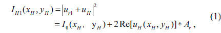
    Only with the two recorded interferograms IH1 and IH2, we can reconstruct the original object. In the process, neither the reference wave intensity nor the object wave intensity needs to be recorded for reconstruction of the original image.

       2.2. Hologram Reconstruction

    According to above image recording method, if the reference wave intensity Ar2 and the object wave intensity are measured, the original image can be reconstructed correctly with the elimination of the twin-image noise and the zero-order light. We show that such a goal can be achieved from an algorithm, which determines the reference wave intensity Ar2 directly from the hologram without the actual need to record the reference wave intensity at all.

    We find the reference wave intensity by searching all of the most possible values. From holographic imaging principle, Ar2 should be within 0 and the maximum of IH1, we then construct a parameter called the 2D correlation coefficient to evaluate the correlation of the reconstruction results by single hologram and two-step phase-shifting holograms. Single hologram contains zero-order light and twin image, but based on the two-step phase-shifting holography method, two-step phase-shifting holograms can restrain zero-order light and twin image [12,13]. So if the reference wave intensity we determined is correct, there will be just one minimum point in the CC curve. Consequently, we can reconstruct the original image without convergence errors.

    image

    Where abs (E) denotes the absolute value of (E); ET is the image reconstructed by IH1; E denotes the reconstructed image at different intensity values of the reference wave Ar2 (the value is gotten by searching from 0 to max (IH1) without actual measurements) with two holograms IH1, IH2, which is calculated by Eqs. (9)-(10) with the assumed values Arc2 of the reference wave Ar2,⊗ denotes the 2D correlation operation.

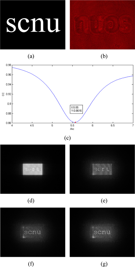
    We then draw the curve of CC versus Arc and set the criterion such that the minimum point of the curve locates the actual value of Ar2 (see Fig. 2(c)). With this found value of Ar2 we can reconstruct the original image based on Eqs. (9)-(11).

    Now in this way only two quadrature-phase holograms are needed to reconstruct the original image without zero-order image and twin-image, and the clear reconstructed image can be obtained at high speed by a certain algorithm.

    The algorithm can be expressed as follows:

    Replace the Ar in Eqs. (1)-(3) with the value Arc found in the above method, so we can construct a complex hologram IC according to

    image

    Where uH is the complex amplitude of the object light on the CCD camera, which is given by uH = Re(uH)+iIm(uH). By taking the square of the absolute value of both sides of Eq. (5), we obtain the solution to a quadratic equation in I0.

    image

    Moreover, from Eqs. (1)-(2), we calculate

    image

    from which, we can write

    image

    Comparing Eq. (6) with Eq. (8), we find that if Arc + Re(uH) + Im(uH) > 0, the minus sign should be chosen for Eq. (6). The quantity of Arc + Re(uH) + Im(uH) will be positive everywhere if the intensity of reference wave is larger than that of the object wave intensity in the CCD plane, which is generally true in practice [12,13]. This will ensure that Eq. (6) takes the minus sign and then we can calculate

    image

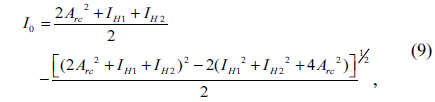
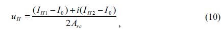
    Then from Eq. (5) we can calculate the complex amplitude in the CCD plane

    image

    According to Eqs. (9)-(10), we can obtain zero-order-and twin-image-free hologram uH(xH,yH) with the two captured quadrature-phase interferograms and the reference wave intensity acquired with above the CC method. Once uH(xH,yH) is known, we can retrieve the complex field in the original object plane P as

    image

    Where IFRz denotes the inverse Fresnel transformation of distance Z. That is to say, original images have been well reconstructed.

    Previously, Liu et al. [15] proposed a seemingly similar correlation method to calculate the reference wave intensity. However, first they defined a different amplitude ratio A from us as

    where R is the amplitude of the reference light on the CCD plane and ϑ denotes the complex amplitude of the object light on the CCD plane, such that when A≥1, only two quadrature phase holograms are needed to obtain a twin-image- and zero-order-free object wave in their method. However, according to the equation, the value of A is related to object wave intensity on the CCD plane and diffraction distance, so in order to reconstruct different original images or dynamic scenes, different object wave intensity on the CCD plane is required to be recorded to judge whether A≥1. In contrast, in our method, we just need to evaluate the amplitude ratio of reference wave intensity and illumination light intensity in the light path. Based on CC calculation, when the amplitude ratio of reference wave intensity and illumination light intensity in the light path is larger than 1.329, the correlation coefficient of the reconstruction object and the original object is 1, thus we can reconstruct original images accurately. So our method can reach the goal to record only two quadrature phase holograms. Secondly, the correlation coefficient defined in their paper, is obviously different from ours.

    III. EXPERIMENTAL RESULTS

    A series of experiments has been made to verify the feasibility of our proposed method. We shall now show a series of results based on the following conditions. The wavelength of the He-Ne laser is 632.8 nm. The quantitative bit depth of the MVC-1000 type CCD is 8 bit and the largest number of pixels is 1280 (H) by 1024 (V) with pixel size of 5.2 μm×5.2 μm. The quantitative bit depth of the Pike F-421 type CCD is 14 bit and the largest number of pixels is 2048 (H) by 2048 (V) with pixel size of 7.4 μm × 7.4 μm. The NEW FOCUS 4002M type electro-optic phase modulator is controlled by a voltage amplifier and a lag wave plate is used for phase modulation.

    First we verify the validity of this method by 2D objects reconstruction experiments. The object we use is the transmission type object “SCNU”, as shown in Fig. 2(a) with the size of 1.25 cm × 1.25 cm. The parameter that we use is d = 46.1 cm. We regulate the electro-optic phase modulator and set the phases of the reference wave in the first and second exposure to 0 and π / 2 , respectively. We get two quadrature-phase interferograms on the CCD plane, one interferogram IH1 is shown in Fig. 2(b). Based on the idea of CC discussed previously, Fig. 2(c) shows the CC curve for different Arc values. From the figure, if the amplitude of the reference light is smaller than 0.34, there will exist convergence errors. However, this situation will not appear in the experiments. With the increase of the reference wave amplitude, there will be just one minimum point in the CC curve. And the true amplitude of the reference wave is 5.55. Fig. 2(e) shows the reconstruction by using the value found in the CC method corresponding to those of Fig. 2(c). Reconstruction results of single hologram and reconstruction results by subtracting the mean value and mean filtering are shown in Fig. 2(d), (f) and (g). Compared with Fig. 2(d), Fig. 2(e) using our method shows a zero-order-and twin-image-free reconstruction image and we can get a clear reconstruction result by subtracting the mean value (see Fig. 2(f)) and mean filtering (see Fig. 2(g)).

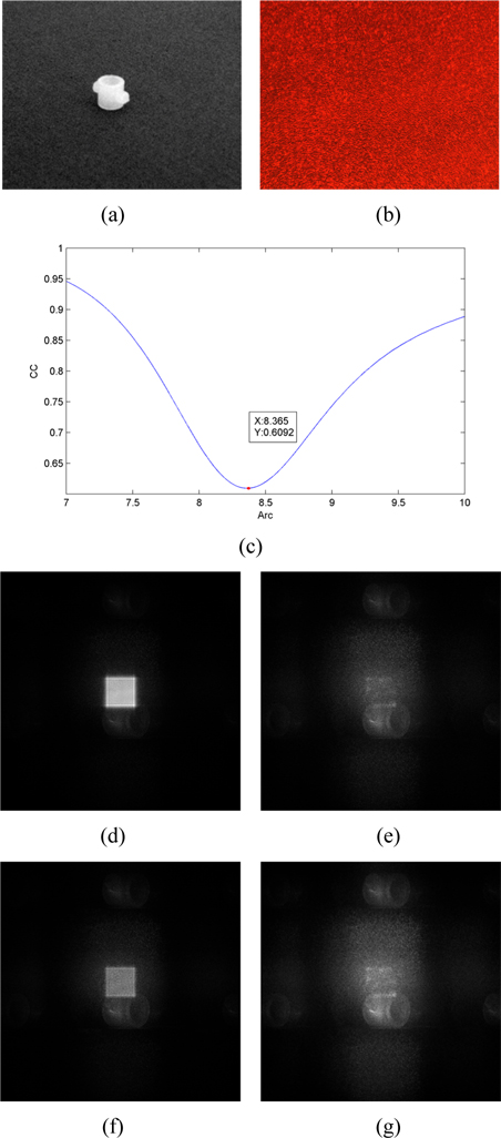
    Then, the 3D objects reconstruction has been tested. The object we use in this experiment is a plastic ring is as shown in Fig. 3(a) with size of 6 mm × 6 mm × 6 mm. The parameter is d = 34.7 cm. We regulate the electro-optic phase modulator for 3D objects. According to 2D method, the true value of the reference wave is 8.37 (see Fig. 3(c)). Finally, we obtain the reconstruction image, as shown in Fig. 3(e). Reconstruction results of single hologram and reconstruction result by subtracting the mean filtering are shown in Fig. 3(d) and (g). From the pictures we can see that we can also reconstruct the 3D original object with zero-order-and twin-image-free.

    To further investigate the effectiveness of our method, we reconstruct the object by four-step phase-shifting holography, as shown in Fig. 3(f). Due to the limitation of our experimental instrument, the experimental result for four-step phase-shifting digital holography is not ideal. However, with this limitation, the reconstruction result by the two-step phase-shifting holography method is better than the reconstruction result by four-step phase-shifting holography. Therefore, in the low-level optical equipment conditions, two-step phase-shifting holography can work better than four-step phase-shifting holography. And our method will also get ideal results in the high precision equipment conditions as well as in four-step phase-shifting holography. So the method proposed in this paper is effective not only in the high precision equipment conditions but also in the low-level optical equipment conditions. The results of the experiments show that our method not only can be applied to 2D object reconstruction, but also can be applied to 3D object reconstruction.

    IV. CONCLUSIONS

    In this paper the two-step phase-shifting digital holography based on the calculated intensity of reference wave algorithm is proposed. With only two captured quadrature-phase holograms known, in addition to the acquired reference-wave intensity, which is not directly recorded in advance but calculated from CC method with two holograms, the clear retrieved image can be reconstructed at high speed. We can obtain clear reconstruction images without reference-wave intensity or object-wave intensity measurement. In the traditional two-step phase-shifting digital holography method, object wave intensity and the reference wave intensity need to be recorded to reconstruct the original image. Due to the high storage requirement of image data and long recording time, these methods have some difficulty particularly in real-time dynamic measurement. Compared with traditional two-step phase-shifting digital holography, our method just need to calculate the reference wave intensity by the CC method instead of recording object wave intensity and reference wave intensity. In this method, our system need to record only two quadrature phase holograms and we don't need to record other data on the CCD plane. It greatly reduces the recording time. For real-time dynamic measurement, we just need to modulate the phase rapidly by phase shifter and get synchronization measurement on the CCD plane to achieve real-time dynamic imaging. In addition, our method can also be used in one-step parallel phase-shifting digital holography to simplify the system. So, this proposed method can improve the speed of holographic imaging and can be considered as a real-time solution. For 3D objects, two-step phase-shifting holography works better than four-step phase-shifting holography. It reduces by half the storage requirements of the digital hologram. The results of the experiments show that the algorithm we proposed is effective. We believe that the method proposed in this paper will be widely used in parallel holography [17,18], and will provide an effective solution to the real-time and dynamic holographic field.

참고문헌
  • 1. Huang T. S. 1971 “Digital holography,” [Proc. IEEE] Vol.59 P.1335-1346 google
  • 2. Jueptner W., Schnars U. 2005 Digital Holography: Digital Hologram Recording, Numerical Reconstruction, and Related Techniques, Chapter 3 google
  • 3. Depeursinge C. 2006 “Digital holography applied to microscopy,” P.95-143 google
  • 4. Tahara T., Ito K., Kakue T., Fujii M., Shimozato Y., Awatsuji Y., Nishio K., Ura S., Kubota T., Matoba O. 2010 “Parallel phase-shifting digital holographic microscopy,” [Biomedical Optics Express] Vol.1 P.610-616 google
  • 5. Weigel D., Elsmann T., Babovsky H., Kiessling A., Kowarschik R. 2013 “Combination of the resolution enhancing image inversion microscopy with digital holography,” [Opt. Commun.] Vol.291 P.110-115 google
  • 6. Cai L., Meng X., Wang Y., Shen X., Dong G., Yang X. 2006 “Virtual shearing interferometry by digital holography,” [Opt. Commun.] Vol.259 P.64-69 google
  • 7. Kreis T. 2005 “Holographic Interferometry,” P.35-219 google
  • 8. Gil S. K., Jeon S. H., Kim N., Jeong J. R. 2006 “Successive encryption and transmission with phase-shifting digital holography,” [in Integrated Optoelectronic Devices, Proc. SPIE] Vol.6136 P.613615-1~613615-8 google
  • 9. Tajahuerce E., Javidi B. 2000 “Encrypting three-dimensional information with digital holography,” [Appl. Opt.] Vol.39 P.6595-6601 google
  • 10. Carmona P. L., Javidi B., Pla F., Tajahuerce E. 2013 “Photon counting 3D object recognition using digital holography,” [Photonics Journal] Vol.5 P.6900309 google
  • 11. Javidi B., Tajahuerce E. 2000 “Three-dimensional object recognition by use of digital holography,” [Opt. Lett.] Vol.25 P.610-612 google
  • 12. Guo P. Y., Devaney A. J. 2004 “Digital microscopy using phase-shifting digital holography with two reference waves,” [Opt. Lett.] Vol.29 P.857-859 google
  • 13. Meng X., Cai L., Xu X., Yang X., Shen X., Dong G., Wang Y. 2006 “Two-step phase-shifting interferometry and its application in image encryption,” [Opt. Lett.] Vol.31 P.1414-1416 google
  • 14. Tahara T., Ito K., Fujii M., Kakue T., shimozato Y. 2010 “Experimental demonstration of parallel two-step phase-shifting digital holography,” [Opt. Express] Vol.18 P.18975-18980 google
  • 15. Liu J. P., Poon T. C. 2009 “Two-step-only quadrature phase-shifting digital holography,” [Opt. Lett.] Vol.34 P.250-252 google
  • 16. Li J., Li Y., Wang Y., Li K. 2014 “Two-step holographic imaging method based on single-pixel compressive imaging,” [J. Opt. Soc. Korea] Vol.18 P.146-150 google
  • 17. Shaked N. T., Newpher T. M., Ehlers M. D., Wax A. 2010 “Parallel on-axis holographic phase microscopy of biological cells and unicellular microorganism dynamics,” [Appl. Opt.] Vol.49 P.2872-2878 google
  • 18. Awatsuji Y., Tahara T., Kaneko A., Koyama T., Nishio K., Ura S., Kubota T., Matoba O. 2008 “Parallel two-step phase-shifting digital holography,” [Appl. Opt.] Vol.47 P.183-189 google
이미지 / 테이블
  • [ FIG. 1. ]  Setup of image recording with two-step-only quadrature phase-shifting digital holography.
    Setup of image recording with two-step-only quadrature phase-shifting digital holography.
  • [ ] 
  • [ ] 
  • [ ] 
  • [ ] 
  • [ FIG. 2. ]  The experimental results of two-step algorithm based on the calculated intensity of reference beam for 2D objects: (a) original image, (b) one of the two holograms, (c) the curve of correlation coefficient versus reference wave amplitude Arc, (d) reconstruction result of single hologram, (e) reconstruction result using our method, (f) minus the mean value of (e), (g) mean filtering of (f).
    The experimental results of two-step algorithm based on the calculated intensity of reference beam for 2D objects: (a) original image, (b) one of the two holograms, (c) the curve of correlation coefficient versus reference wave amplitude Arc, (d) reconstruction result of single hologram, (e) reconstruction result using our method, (f) minus the mean value of (e), (g) mean filtering of (f).
  • [ ] 
  • [ ] 
  • [ ] 
  • [ ] 
  • [ ] 
  • [ ] 
  • [ ] 
  • [ FIG. 3. ]  The experimental results of two-step algorithm based on the calculated intensity of reference beam for 3D objects: (a) small plastic ring using as 3-D object, (b) one of the two holograms, (c) the curve of correlation coefficient versus reference wave amplitude Arc, (d) reconstruction result of single hologram, (e) reconstruction result using our method, (f) reconstruction result using four-step phase-shifting holography, (g) mean filtering of (e).
    The experimental results of two-step algorithm based on the calculated intensity of reference beam for 3D objects: (a) small plastic ring using as 3-D object, (b) one of the two holograms, (c) the curve of correlation coefficient versus reference wave amplitude Arc, (d) reconstruction result of single hologram, (e) reconstruction result using our method, (f) reconstruction result using four-step phase-shifting holography, (g) mean filtering of (e).
(우)06579 서울시 서초구 반포대로 201(반포동)
Tel. 02-537-6389 | Fax. 02-590-0571 | 문의 : oak2014@korea.kr
Copyright(c) National Library of Korea. All rights reserved.