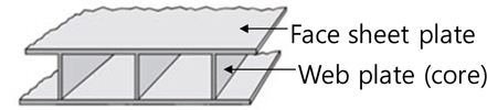
The research of steel sandwich panels has been extensively carried out for the past decades. Among the sandwich panel, Icore panels offer high strength to weight and stiffness to weight ratios, making them favorable in transport industry, especially shipping. Moreover, these panels are proved to be more resistant to impact and blast loads and space efficiency is good to fill different systems such as piping and wiring (Kujala et al., 2005; Yourlmaz et al., 2009). I-core sandwich panel is composed of two face sheet plates and web plates (called cores) welded perpendicular to the face sheet plates. CO2 laser welding is adopted for T-joint welding between a core and a face plate due to its merits of narrow heat affected zone, small welding deformation, and deep penetration capability. CO2 laser welding is known to induce less welding deformation than other conventional welding methods, however, the deformation level is still not ignorable in the sandwich panel since it consists of quite thin plates of 3-5
Kim et al. (2013) proposed a simple volumetric heat source model of laser welding for I-core sandwich including the defocus phenomenon. For a verification of the proposed model, heat transfer analysis and thermal elasto-plastic analysis are performed to investigate heat distribution in the thickness direction and the resultant welding deformation, respectively.
Table 2 summarizes a few researches on welding deformation induced by laser welding. Moraitis and Labeas (2008) used 3D Gaussian model for a butt weld of DH36 steel plate and a lap joint of aluminum alloy. Heat transfer analysis and thermalelasto- plastic analysis was performed to simulate welding residual stress and deformation distortion using 3D solid element. An efficient keyhole model, which is independent of any empirical parameter, is introduced for the prediction of the keyhole size and shape required for the thermal analysis.
Tsirkas et al. (2003) simulated the laser welding process to predict laser welded panel distortions for butt joint specimen that consists of thick AH36 shipbuilding steel plates, using different welding parameters. Experimental testing was carried out to measure the distortion. Zain-ul-Abdeina et al. (2009) focused on the prediction of welding-induced distortions and residual stresses on thin sheets of 6056-T4 aluminum alloy. Cone-shaped volumetric heat source with Gaussian distribution and an upper hollow sphere is used to attain the required weld fusion zone size and temperature fields. From a comparative study of experimental and simulation results, a friction coefficient and a suction pressure to provide the best agreement in out-of-plane and in-plane displacements were found. Zain-ul-Abdeina et al. (2010) used a 3D volumetric conical heat source with Gaussian distribution without the hollow sphere for a fillet weld of T-joints made from 6056-T4 aluminum alloy. A comparative analysis of the experimental and simulation results showed a good agreement in temperature and displacement fields.
As an alternative to time-consuming thermal elasto-plastic analysis using 3D solid model, Sulaiman et al. (2011) developed a new linear elastic shrinkage method, named “Weld Planner”, to simulate welding deformation for GMAW process. Shell elements were used for the modeling of both plates and weld beads, which lead to more reduction in the computational time. It was employed to predict welding distortion induced in butt and T-joints of steel plates with thickness of 4
The above mentioned researches treated a butt weld or a conventional filet weld. Thus, deep penetration is not needed and the consideration of defocus has not been taken into account. However, T-joint of sandwich panel requiring a laser shooting on face plate requires a deep penetration into the upper part of core. This is enabled by the defocus of laser shooting and it should be incorporated into the heat source model.
In addition, those researches treated simple plates and the computational time is not significant. However, a sandwich panel consists of many core plates and the correct prediction of welding deformation can be made by accumulating the welding deformation for all T-joints. In this regard, thermal elasto-plastic FE analysis using solid model is quite time consuming. Thus, shell element model with virtual layers are employed to reduce the computational time. The heat load can be distributed through thickness by generating virtual layers and applying power densities to virtual nodes in this study.
This study focuses on a practical purpose how to make use of shell element model aiming at reducing the computational time without a deterioration of accuracy in the analysis results. Even if it is not based on robust theoretical background, the idea proposed in this study is expected to be directly applied to the actual engineering work and offer a concrete benefit.
This paper is unfolded as follows. First, volumetric heat source model to be used in this research is briefly defined. A new approach, named “Hetero-layered approach (HLA)” is proposed along with a simple illustrating example and a study on the number of layer of face plate. It is followed by a verification work to compare the temperature distribution on the cross section and welding deformations among the proposed method, a conventional method to use 3D solid elements and experiment results. The computational time of the proposed method as well as the welding deformation is also compared with the conventional method through four comparative studies. Finally, a conclusion is laid.
[Table 1] Researches on a prediction of welding deformation and residual stress for laser welding.
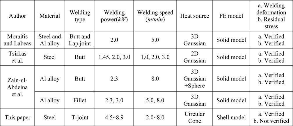
Researches on a prediction of welding deformation and residual stress for laser welding.
VOLUMETRIC HEAT SOUCE MODEL CONSIDERING DEFOCUS (
>
Volumetric heat source model considering defocus
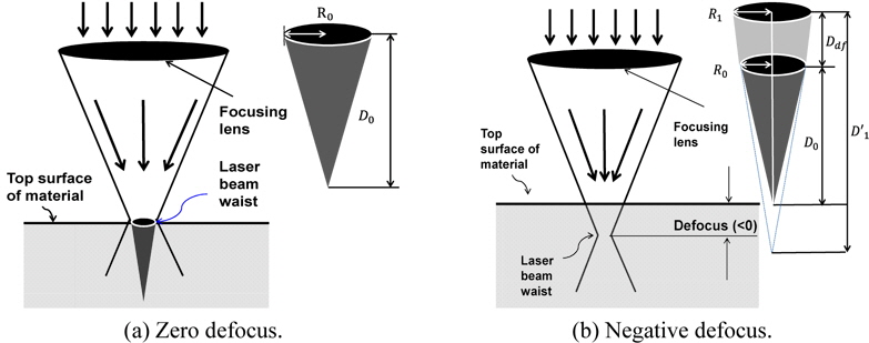
Kim et al. (2013) suggested a cone-shaped volumetric heat source model realizing the negative defocusing as shown in Fig. 2. It shows how to extend the proposed heat source model considering the negative defocus.
When defocus is zero, the heat source is assumed as a circular cone whose radius is

where, R1 : Radius of heat source for negative defocus R0 : Radius of heat source for zero defocus (= Radius of laser beam waist = 0.5mm) Rfl : Radius of focusing lens (=15.5mm) Lf : Focal length (=150mm)
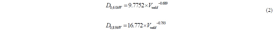
Empirical formulas obtained from a series of experiments for the depth of heat source for zero defocus (=

From the above defined

Laser heat energy multiplied by total welding efficiency (=


when defocus is negative,

where,
For an assessment of welding deformation, 3D solid FE model has been employed for heat transfer analysis and thermal elatsto-plastic analysis in order to reflect heat load distribution across the thickness. However, even if a high performance computer is utilized, the assessment of welding deformation using 3D solid FE model is still quite time consuming. It is a big burden for prediction of welding deformation for a real scaled model.
For example, when thermal elasto-plastic analysis is performed for a 0.5
>
Suggestion of ‘HLA’ in shell element model
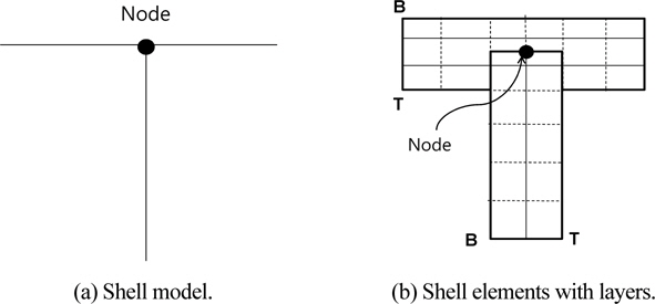
FE model of T-Joint with shell element has one node connection between face plate and web plate as shown in Fig. 3(a). Some layers need to be defined in shell element in order to impose heat distribution in thickness direction. In Fig. 3(b), the face plate and the core have four layers and three layers (including top and bottom layers) across thickness, respectively.
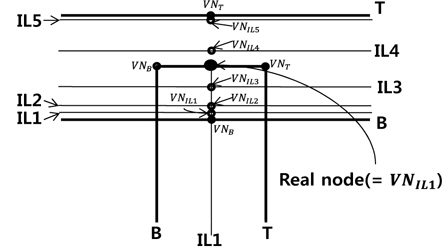
This study proposes a method to define different number of layers for face plate from core and to distribute unevenly. Its purpose is to impose heat load only for the face plate at the joint. Fig. 4 depicts a shell model with seven layers for face plate and three layers for core including top and bottom surfaces. Between top (=
The locations of layers need to be carefully set up.
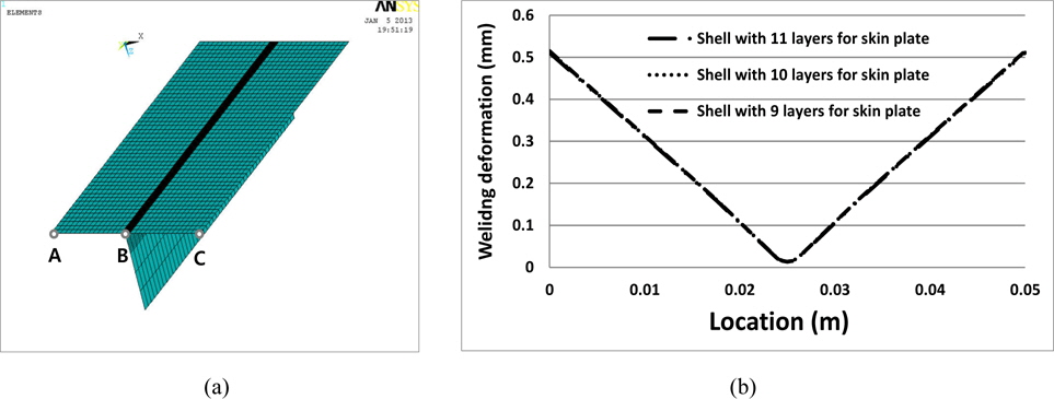
The proposed HLA can be verified in a simple thermal elasto-plastic analysis as depicted in Fig. 5. The analysis model is a simple T-joint constructed with shell elements. The size of the model is 50
>
Study on the number of layers of face plate
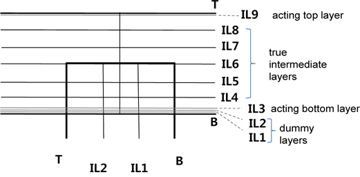
Intermediated layers of face plate can be classified into three as illustrated in Fig. 6.
First, dummy layers corresponding to intermediate layers of core. These layers are not used and the number should be the same as the intermediate layers of core.
Second, two acting layers replacing top and bottom layers of face plate. These layers are introduced to replace exiting top and bottom layers of the face plate. Heat loads of the original top and bottom layers are imposed on these layers. One acting layer should be placed quite close to top layer and the other bottom layer.
Third, true intermediate layers. These layers are evenly distributed and the actual heat distribution across the thickness is realized by applying heat loads to virtual nodes at these layers. The sufficient number of layers should be created to accurately incorporate continuous variation through the thickness.
Therefore, the number of layers of face plate is determined as follows.
NILF = NILC + NAL + NTL
NILF : The number of intermediate layers of face plate NILC : The number of intermediate layers of core NAL : The number of two acting layers NTL : The number of true layers of face plate
The number of true intermediate layers needs to be selected carefully since it can affect thermal elasto-plastic FE analysis, while the numbers of the other two layers are fixed and not affective to the result. A parametric study for different number of true intermediate layers is carried out to investigate its effect on the welding deformation.
[Table 2.] Definitions of three case studies.

Definitions of three case studies.
Here, the above-defined circular-cone type volume heat load is applied and other welding conditions are defined below.
- Laser power = 7.5kW - Welding speed = 2m/min - Defocus = 0mm
Fig. 7(a) is the analysis model and Fig. 7(b) shows the calculated welding deformation at point A, B and C and the difference of maximum deformation among three cases are found to be below 1%. From the results, five true layers can be seen sufficient to realize the heat distribution across the thickness and more layers is meaningless.
VERIFICATION OF HETERO-LAYERED APPROACH
>
Comparison of welding deformations
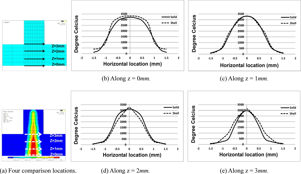
Heat transfer analysis using HLA in shell element model is carried out and the resultant heat distribution is compared with that with solid element model as shown in Fig. 8. Temperature distributions along four horizontal lines are compared and good agreements are identified.
There are two ways in checking the agreement of temperature distribution. One is to compare the difference of two maximum temperatures and the other is the maximum difference in two temperature distributions. The former is more generally used since the distribution of high temperature in transverse direction is the most influential to the welding deformation and the maximum temperature can be a representative value for the distribution.
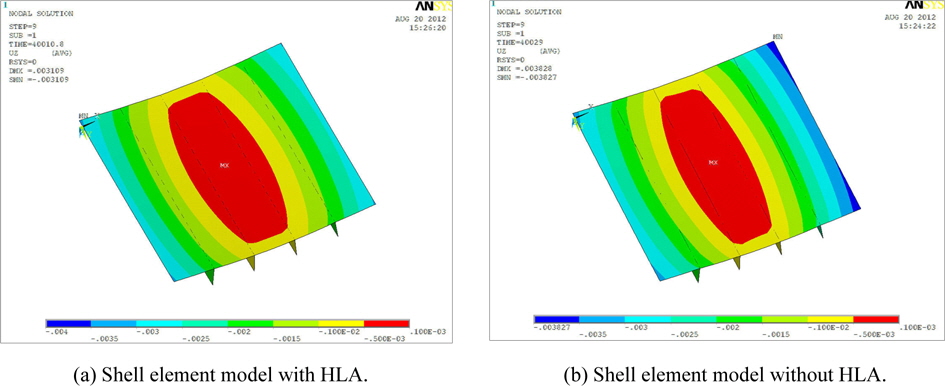
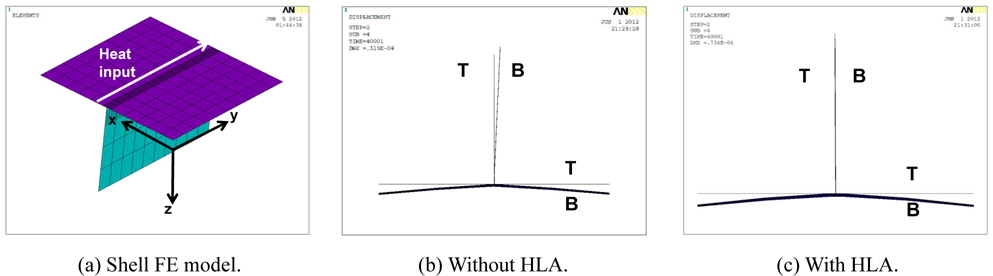
To validate the proposed HLA, thermal elasto-plastic analysis is performed and welding deformation is compared with that from solid FE model and that from shell element model without the HLA. The proposed volumetric heat source model is used and other conditions. Fig. 9 compares vertical welding deflection from shell element model with and without HLA. Overall tendencies are nearly the same, but when HLA is not employed, the maximum vertical deflection becomes about 20% larger.
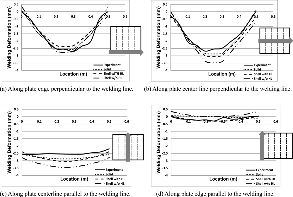
The welding deformations along four lines are compared together with solid element model and experiment result in Fig. 10. ‘Shell with HL’ indicates a case of shell element model with HLA and ‘Shell w/o HL’ a case without the approach. It is identified that the result of shell element with HLA coincides well with the experimental result as well as solid element analysis results.
As listed in Table 3 the difference between shell model with HLA and the experiment is close to that of solid model. When HLA is not employed, unintended heat load causes a deformation of core and it affects to the deformation of face plate as well.
[Table 3] Comparison of max. deformations.
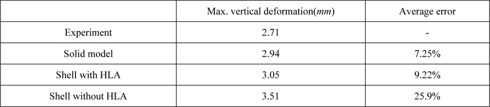
Comparison of max. deformations.
>
Comparison of computational time of shell model with HLA and solid model
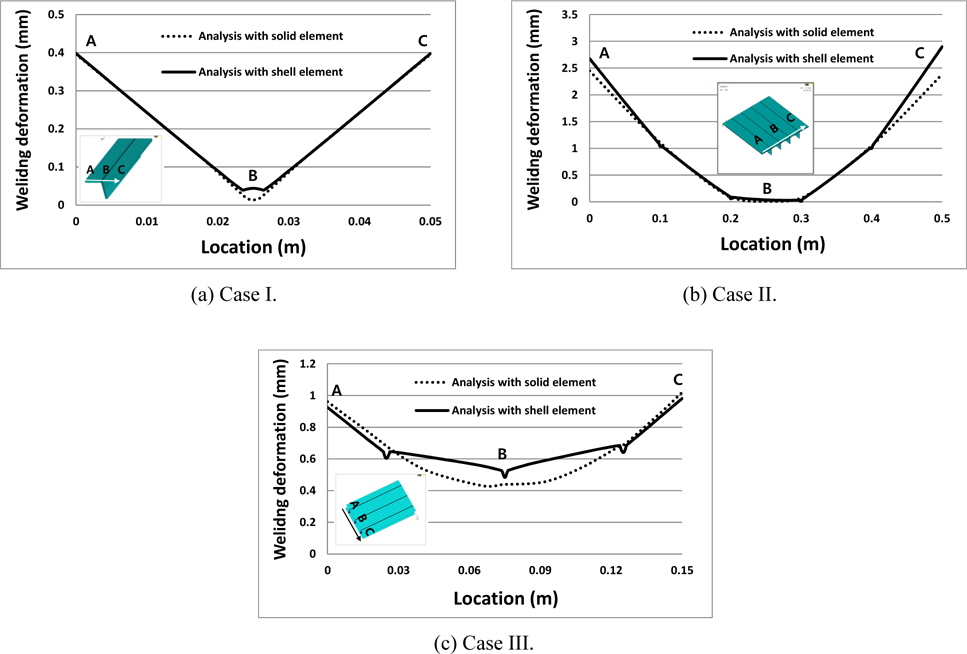
In the previous section, the prediction of shell model with HLA shows a good coincidence with solid model. More cases are compared to validate the advantages of shell model in terms of computational time. Three cases are defined as follows and the FE models are summarized in Table 4.
- Case I : single-sided model with one core - Case II : single -sided model with four cores - Case III : double-sided model with three cores
[Table 4] FE models of three case studies.
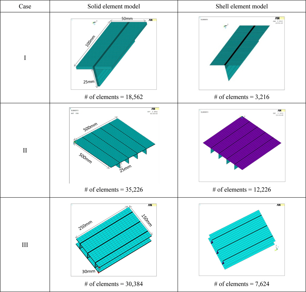
FE models of three case studies.
In general, the number of elements used in solid model is much larger than that of shell model since the solid model uses a few elements across the thickness while the shell model defines virtual layers. Laser welding conditions are defined in Table 5. The above-defined volumetric heat sources are imposed on both actual nodes of 3D solid model and virtual nodes of shell model. The power with efficiency is divided by the number of nodes located inside the keyhole and the value is applied to the nodes.
[Table 5] Laser welding conditions of three cases.
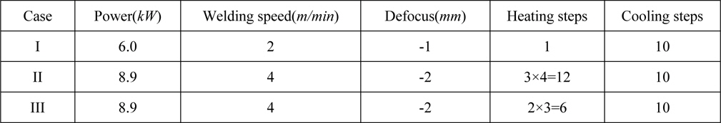
Laser welding conditions of three cases.
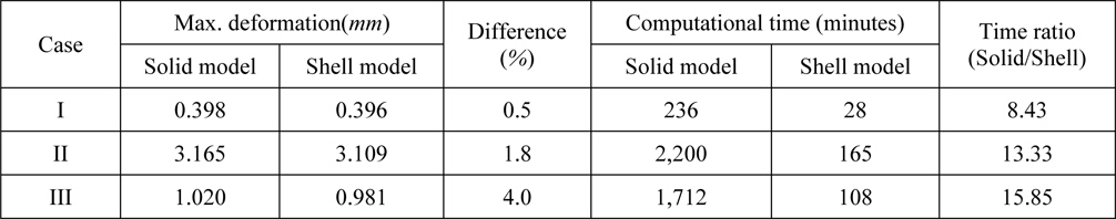
Fig. 11 shows the shape of vertical welding deformations in transverse direction of solid model and shell model and Table 6 summarizes maximum deformations at the edge of both sides. The difference between the solid model and shell model are below 5%. It can be regarded that analysis results with shell element have good agreement with analysis using solid element. On the other hand, the computational time of solid models are much longer than that of the corresponding shell models. The ratio of the computational times ranges from about 8.0 to 16.0. It is mainly due to the larger number of solid elements of solid model and the larger degree of freedom of solid element than those of shell element model.
[Table 6] Results of case studies.

Results of case studies.
Thermal elasto-plastic analysis using solid element model requires considerably long computational time due to its large number of elements and the inherent large degree of freedom of solid element. In this paper, a new method named HLA is suggested for the thermal elasto-plastic analysis for T-joint laser welding. It aims at the reduction of computation time by employing shell element model instead of solid element model. It enables to impose the same heat load at joint as solid element model by defining more intermediate layers at the face plate than the core. From, a heat transfer analysis, the resultant heat distribution on the cross section in the vicinity of the welding joint is observed to be nearly the same as that of solid element model. A thermal elasto-plastic analysis shows a good agreement of welding deformation between shell element model and solid element model.
With respect to computational time, three case studies are carried out. Thermal elasto-plastic analyses are carried out for both solid element model and shell element model and out-of-plane welding distortion and the computational time are compared. From the study, the proposed HLA can reduce the computational time by about 1/8 to 1/16 and the difference of maximum welding deformation remains below 5%. Conclusively, the application of HLA to thermal elasto-plastic analysis using shell elements is expected to cut down the computational time drastically while keeping the accuracy within tolerable level. This advantage may be more remarkable when predicting the welding deformation for real scaled sandwich panel.
The proposed method is expected to be applied to other welding methods to require deep penetration like electron beam welding for thick plate or laser welding at fillet joint. The target of the welding simulation can be also extended to other types of sandwich panels with different cores like corrugated cores, cup shaped cores, honeycomb cores, and so on. HLA is expected to enable an optimization the welding condition to enhance weldability while reducing welding deformation through a drastic reduction of computational time.