Low cycle fatigue (LCF) damage is known as one of the main degradation mechanisms of structural materials in nuclear power plants (NPPs) [1,2]. It has been one of the key areas of technical evaluation and safety review required for the life extension application of operating reactors as well as for the design and licensing of new reactors. Although ASME Boiler and Pressure Vessel Code Section III specifies the design fatigue curves for structural materials used in NPPs, these design curves do not specifically include the effects of corrosive environments of the nuclear coolant system on low cycle fatigue lives [3]. To evaluate the effects of nuclear water chemistry environments, extensive laboratory testing has been conducted both in Japan [2] and the United States, mostly at Argonne National Laboratory (ANL) [1,4]. They evaluated the effects of the various material, environmental, and loading parameters that influence fatigue crack initiation and propagation. Eventually, U.S. NRC issued a NUREG/CR-6909, in which extensive test data on environmental fatigue were presented and analyzed to develop models for carbon and low-alloy steels (LASs), stainless steels (SSs), and Ni-Cr-Fe alloys [1]. With the technical basis of NUREG/CR-6909, U.S. NRC issued RG-1.207 and requested the consideration of the detrimental effects of primary coolant environments in the design and construction of the Class I components of new nuclear power plants [1,5]. Consequently, for reactor vendors intending to build new reactors in the United States, such a regulatory requirement was quite a burden in the application of design certificates of advanced reactors docketed after the issuance of RG-1.207.
In Korea, the issue of environmental fatigue was raised in the technical evaluation of the key components of Kori 1 for continued operation application [6]. About the same time, APR1400 was being developed, and how to deal with the environmental fatigue in design and licensing process was the subject of debate among the utility, regulator, and plant designer engineers. Faced with the lack of proper regulatory guidance and consensus among the technical groups, a tentative knock-down factor was applied to incorporate the environmental effect in fatigue design of primary system components in APR1400. Meanwhile, despite the very active test programs in the United States and Japan, no such program was present domestically. In addition, some of the key structural materials widely used in APR1400 were tested insufficient numbers in the foreign test programs [1,2]. Thus, the Korean regulatory body (KINS) raised the necessity of a domestic testing program focusing on verifying the applicability of suggested models to APR1400, establishing the sufficient database for the materials in APR1400, and technical justification of a tentative knock-down factor. In accordance with these necessities, a Korean environmental fatigue test program for the structural materials was initiated and is still underway. In this paper, the test and key analysis results of low alloy steels, stainless steels, and Ni-Cr-Fe alloys are briefly summarized. Finally, an on-going test program on the hot-bent 347 stainless steel for the surgeline pipes application is introduced.
2.1 Environmental Fatigue Test System
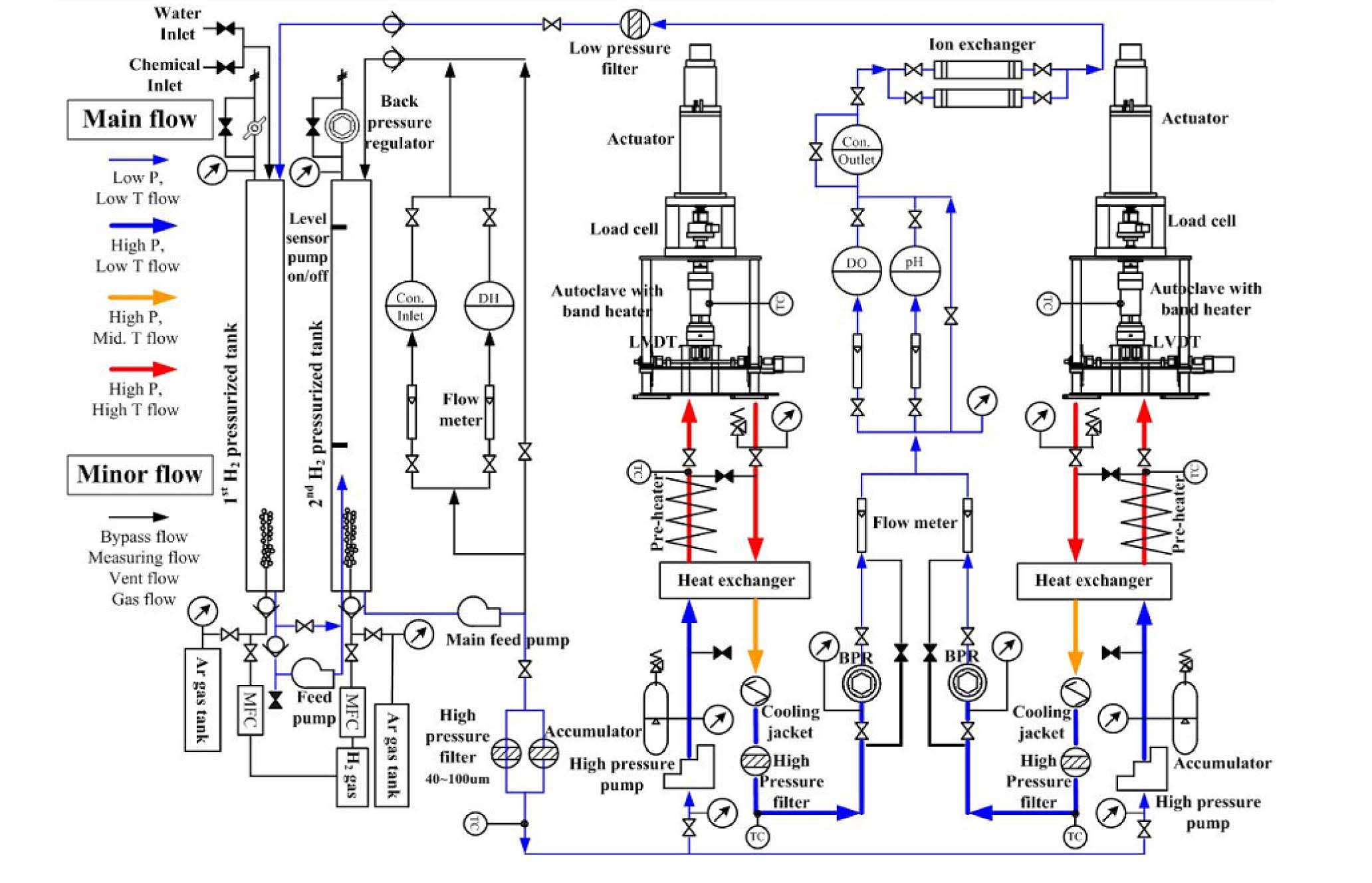
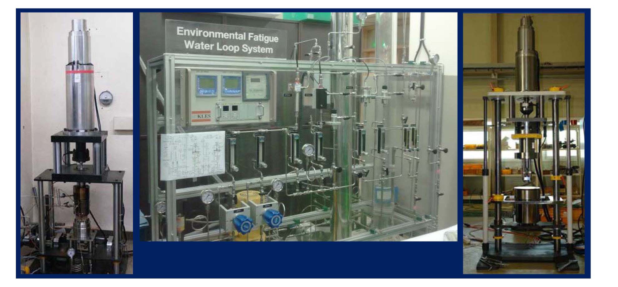
A special set-up equipped with a recirculation-type water loop and two fully reversible loading machines was designed and installed exclusively for the LCF tests in simulated PWR environments. The schematic drawing of the test system is presented in Fig. 1 and the actual system is shown in Fig. 2. In the loop, high purity water with a controlled boric acid and lithium hydroxide concentrations is fed into the 1st water tank. Then the dissolved oxygen (DO) and dissolved hydrogen (DH) concentrations are controlled by bubbling argon gas and hydrogen gas in the 1st tank. When high DH concentration is needed, the 2nd tank is pressurized to achieve the desired DH concentration. Throughout the test, the water chemistry is measured using high accuracy detectors, a DO meter, a DH meter, a pH meter, and two conductivity meters at the inlet and outlet of the autoclaves. Two servo-electric actuators equipped with the autoclave were installed and connected to the water loop. The chemistry controlled water can be supplied to each servo-electric actuator separately by two high pressure metering pumps, and therefore two environmental fatigue tests can be performed at different loading and temperature conditions. To maintain the temperature inside the autoclave within ±2 ℃ of the specified temperature, the auxiliary heater and main heater were mounted in front of each autoclave and autoclave body, respectively.
2.2 Materials in the Environmental Fatigue Test Program
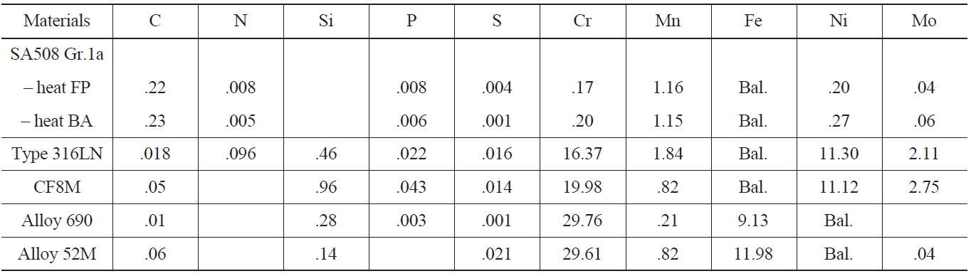
In the LCF test program, three classes of materials were included, such as low alloy steels, stainless steels, and Ni-Cr-Fe alloys. First, SA508 Gr.1a LAS was chosen because it was the material used for the main coolant system pipes of OPR1000 and APR1400, and therefore its environmental fatigue behaviors were considered very important in the licensing of new reactors. In the test, two heats of SA508 Gr.1a LAS with different heat treatment history and microstructures were used. Despite similar chemical composition and tensile properties, heat FP with a ferritepearlite (FP) structure and heat BA with a tempered bainite (BA) structure were used to compare the LCF behaviors between two heats. In the case of SSs, type 316LN and CF8M were used as test materials. A type 316LN SS was used as a material for branch line piping systems like the safety injection system of APR1400. While, a CF8M cast stainless steel was used as the piping material of the reactor coolant system of Westinghouse type NPPs. Type 316LN SS has fully austenite structure, while CF8M has a duplex structure made up of irregular dispersed δ-ferrites in an austenitic matrix. Therefore, the effects of different microstructures on the environmental fatigue behaviors of stainless steels were investigated. Finally, in the case of Ni-Cr-Fe
[Table 1.] Chemical Compositions of Test Materials
Chemical Compositions of Test Materials
alloys, an Alloy 690 base metal and Alloy 52M weld were used as they have been widely used in advanced reactors including APR1400 because of much better resistance to PWSCC (Primary Water Stress Corrosion Cracking) than Alloy 600 and 82/182 welds. Forged Alloy 690, supplied by Goodman Alloys, was solution-annealed at 1060℃ for 3 hours followed by quenching in air. A 52M weld was fabricated by Doosan Heavy Ind. as a dissimilar weld joining SA 508.Gr.3. Cl.1 and STS 304. The chemical compositions of the test materials are described in Table 1 and the results of environmental fatigue tests and subsequent analysis results are summarized in the following sections.
2.3 Test Condition and Methods
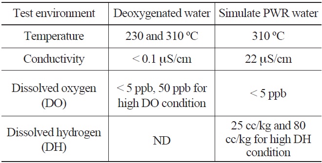
The typical environmental fatigue test environments are shown in Table 2. The deoxygenated water environment was prepared by continuously bubbling argon gas in the demineralized water until a very low dissolved oxygen content (<5 ppb) was achieved. The simulated PWR water environments were prepared by the addition of chemicals (1200 ppm of boric acid and 2.2 ppm of lithium hydroxide) to the demineralized water and controlling the dissolved oxygen and hydrogen contents by gas supply as shown in Fig. 1. The pH of the test solution was maintained in the range of 6.3 ~ 6.5 at room temperature (RT). To investigate the effects of the DO and water temperature on LCF life of LAS and SS, additional LCF tests were conducted at a
[Table 2.] Environmental Fatigue Test Water Chemistry Conditions

Environmental Fatigue Test Water Chemistry Conditions
lower temperature (230℃) and higher DO (50 ppb). Also, the effect of DH on LCF life of SSs and Alloy 690 was investigated by performing additional tests at various DH levels (80 cc/kg for 316LN SS, 0 and 60 cc/kg for Alloy 690).
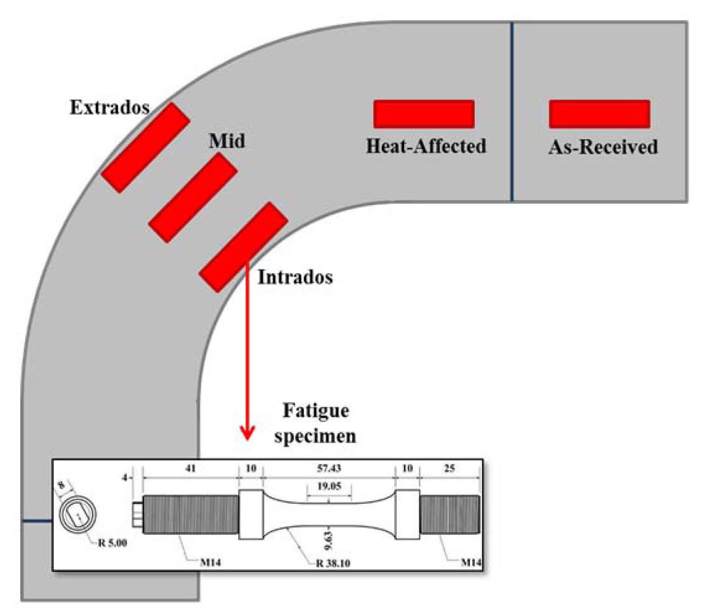
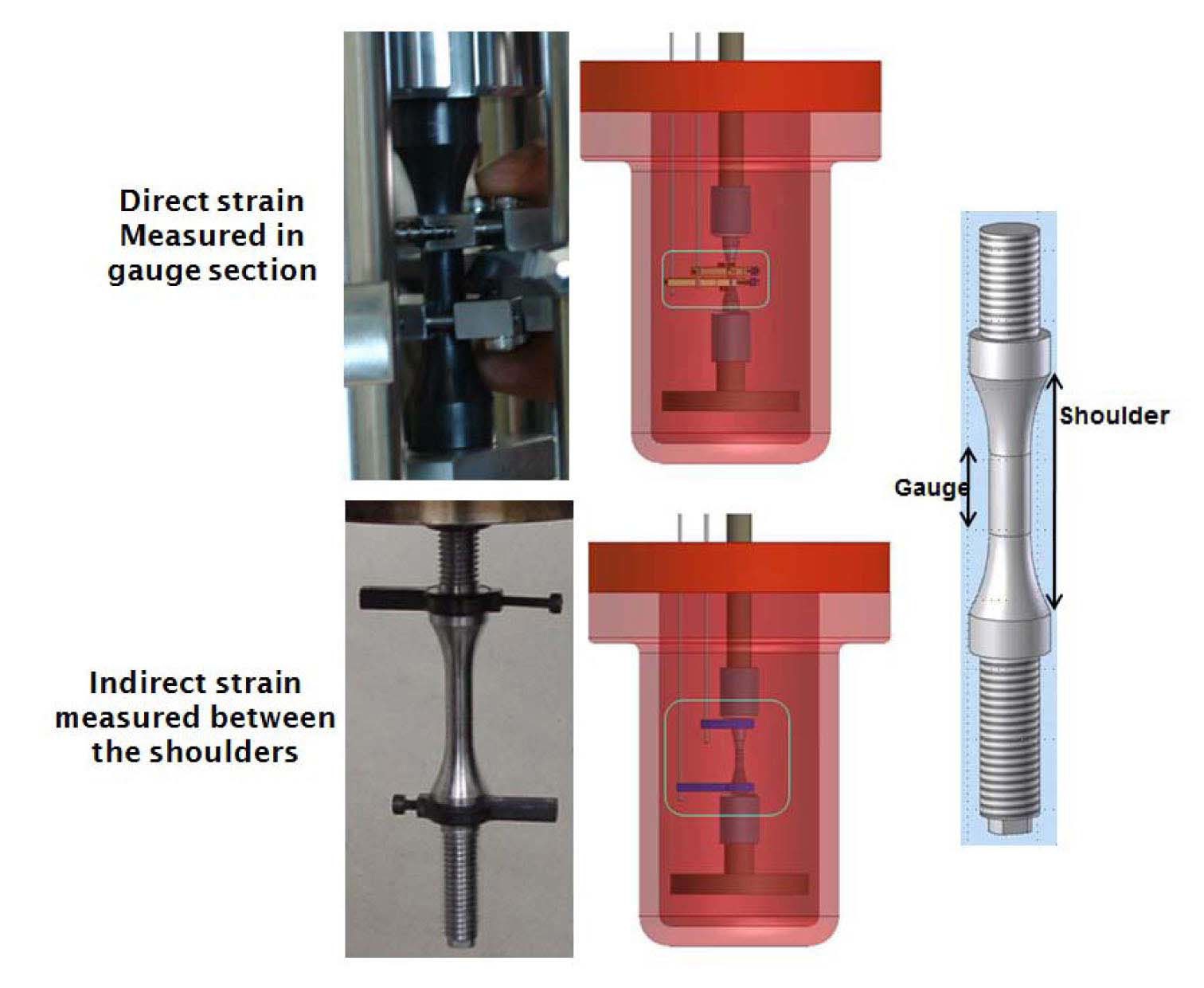
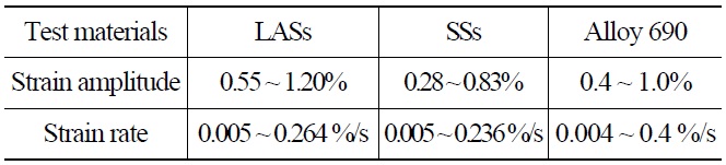
Table 3 shows the loading conditions. The LCF tests were conducted in a strain-controlled mode with a fully reversed triangle waveform. The fatigue specimen was a solid cylindrical type with a gauge section diameter of 9.63mm and a gauge length of 19.05mm [7]. During the LCF test, the strain in the gauge section was indirectly measured using a linear variable differential transformer (LVDT) attached at the shoulders of the specimens. Before the test, the correlations between the strains in the gauge section and at the shoulders were established at test temperatures and strain amplitudes, and then they were used to convert the LVDT data into the strains in the gauge section. The schematics of such measurements are shown in Fig. 3. The LCF tests were terminated when the tensile stress during the fatigue test decreased by 25% from the peak tensile stress value and the corresponding number of cycles, N25, was defined as fatigue life [1,2]. The degree of environmental effect was measured as fatigue life correction factor, Fen, which was defined as the ratio of fatigue life in RT air environment and that in a high temperature water chemistry environment.
[Table 3.] Environmental Fatigue Test Loading Condition

Environmental Fatigue Test Loading Condition
3. ENVIRONMENTAL FATIGUE BEHAVIORS OF SA508 GR.1A LAS
3.1 LCF Behaviors of SA508 Gr.1a LASs
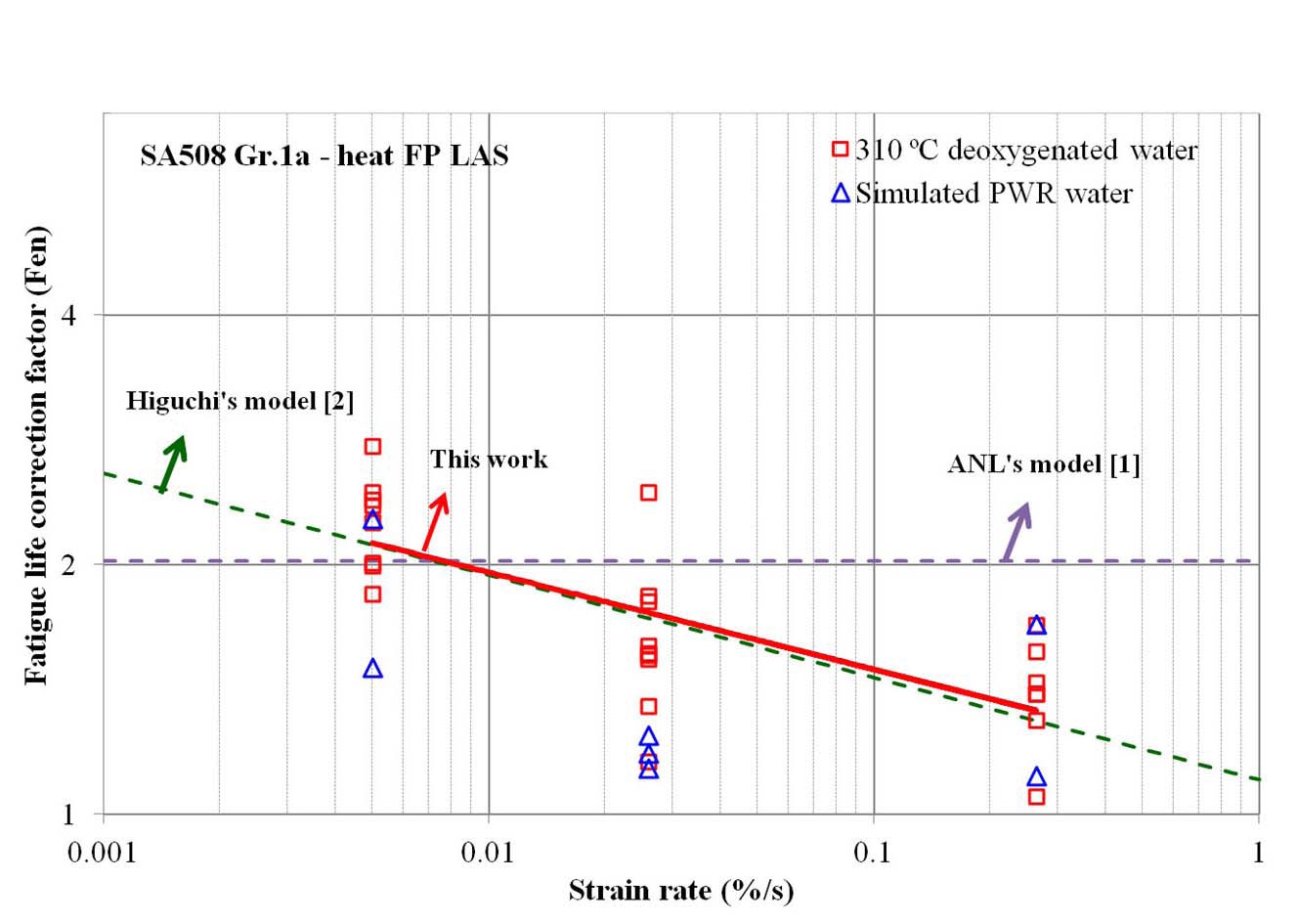
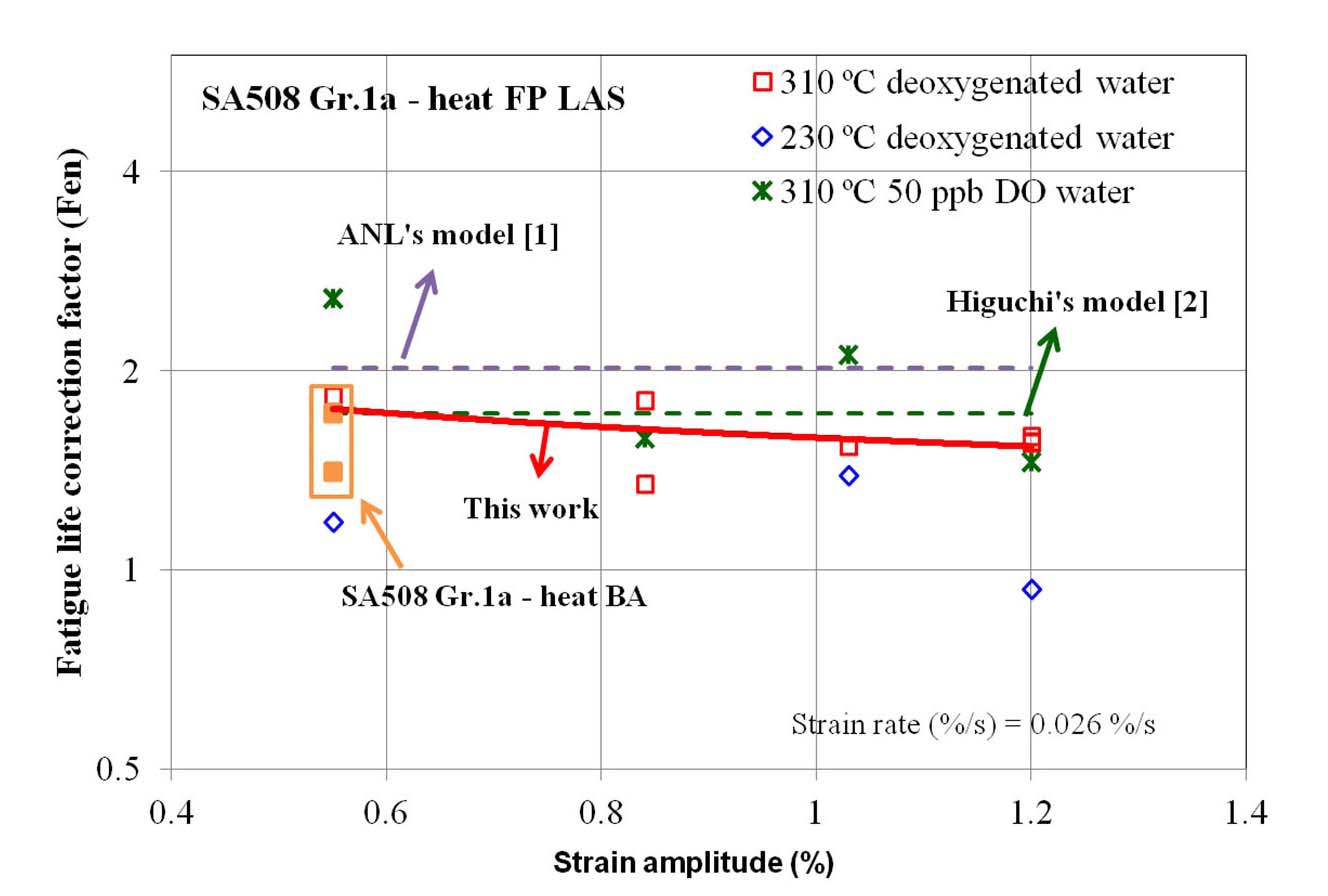
Fig. 4 shows the fatigue life correction factor (Fen) of SA508 Gr.1a-heat FP LAS calculated from the LCF test at 310 ℃. Overall, Fen values at 310 ℃ are similar in deoxygenated and simulated PWR water environments. As shown in the figure, the LCF life in 310 ℃ water was decreased by a factor of 1 ~ 3 compared to that in RT air, which was slowly decreased with increasing strain rate. The Fen values measured from our LCF data were compared with the prediction models, such as ANL [1] and Higuchi [2]. Our test results show relatively good agreement with the Higuchi’s model rather than ANL’s model. In Fig. 5, additional test data at lower temperature (230 ℃) and at higher DO level (50 ppb) are plotted. As expected from the models [1,2], Fen decreased at lower temperature but increased at higher DO level.
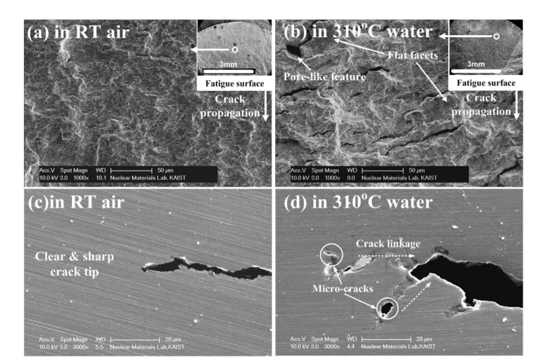
Fig. 6 shows the fatigue crack morphologies of Heat FP of SA508 Gr.1a. The fatigue surface and sectioned cracks revealed that the LCF life in 310 ℃ deoxygenated
water was affected by environmentally assisted cracking (EAC) mechanisms such as metal dissolution and hydrogen induced cracking (HIC) [8]. On the fatigue surface of the specimens tested in 310 ℃ deoxygenated water, the streamed down features of fatigue striations and a blunt shape of a crack tip were observed, which are considered as traces of metal dissolution mechanism [8]. In addition, the brittle cracks and micro-cracks ahead of the crack tip were observed in specimens tested in 310 ℃ deoxygenated water, which are known as the evidence of HIC mechanism. The high hydrogen concentration at the crack tip would be formed due to the stress gradient and enhance the strain localization [9,10]. Thus, the initiation and the growth of micro-cracks could be accelerated by HIC [8]. Therefore, the main EAC mechanisms for the reduction of LCF life in 310 ℃ deoxygenated water could be the metal dissolution and HIC.
3.2 Effects of Microstructure on LCF Behaviors of SA508 Gr.1a LASs
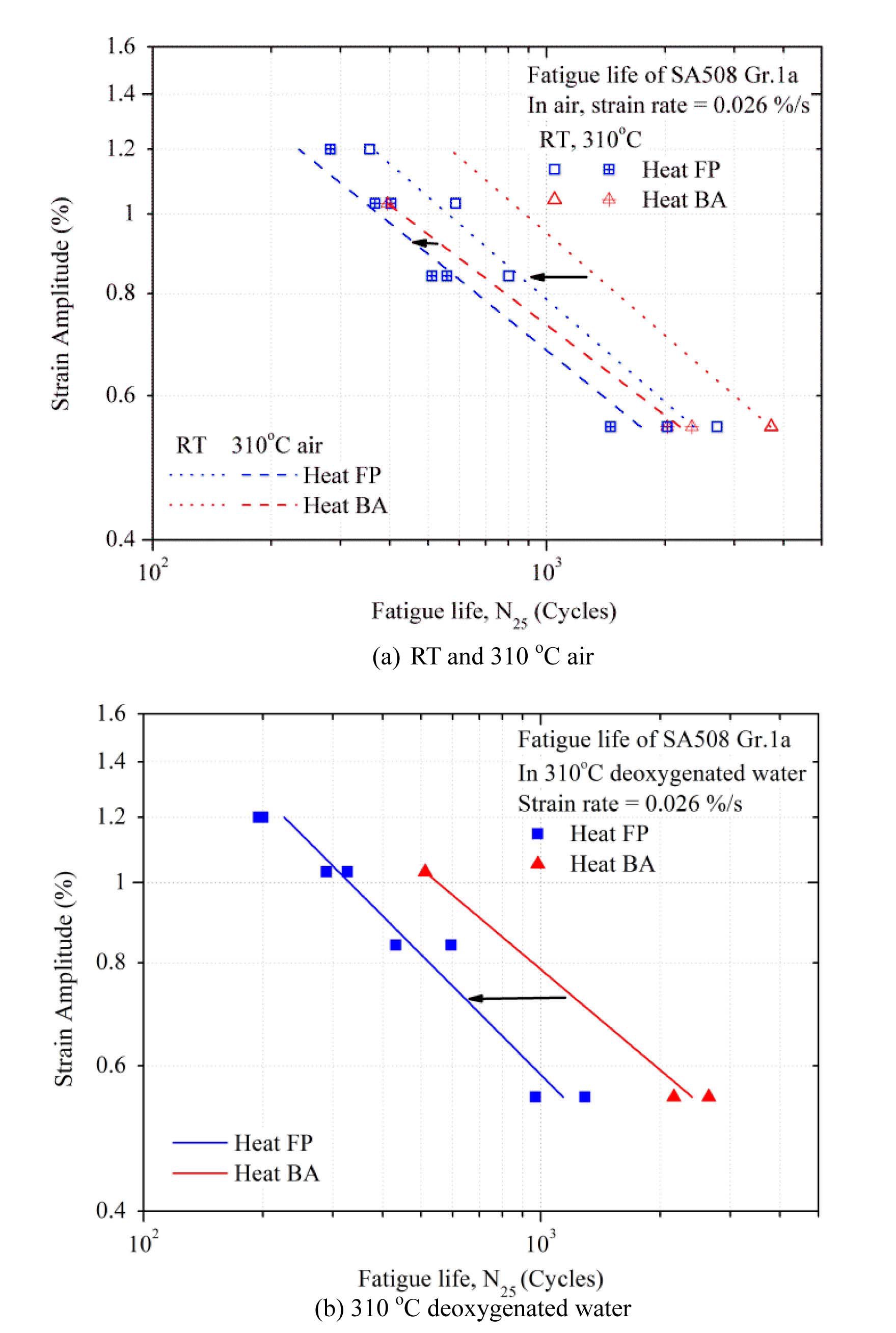
The LCF life of heat BA of SA508 Gr.1a with tempered bainite microstructure was compared with those of heat FP with ferrite-pearlite phase as shown in Fig. 7 [7]. The LCF life of heat FP was shorter than that of heat BA in 310 ℃ deoxygenated water while the LCF life of both heats was slightly shorter or comparable in 310 ℃ air. Because the Fen values of the two heats were similar, as shown in Fig. 5, other factors might have contributed to the difference of LCF life between two heats. Of many possible factors influencing the LCF behaviors in high temperature water environments, authors focused on the dynamic strain ageing (DSA) behaviors and effects of hydrogen on DSA.
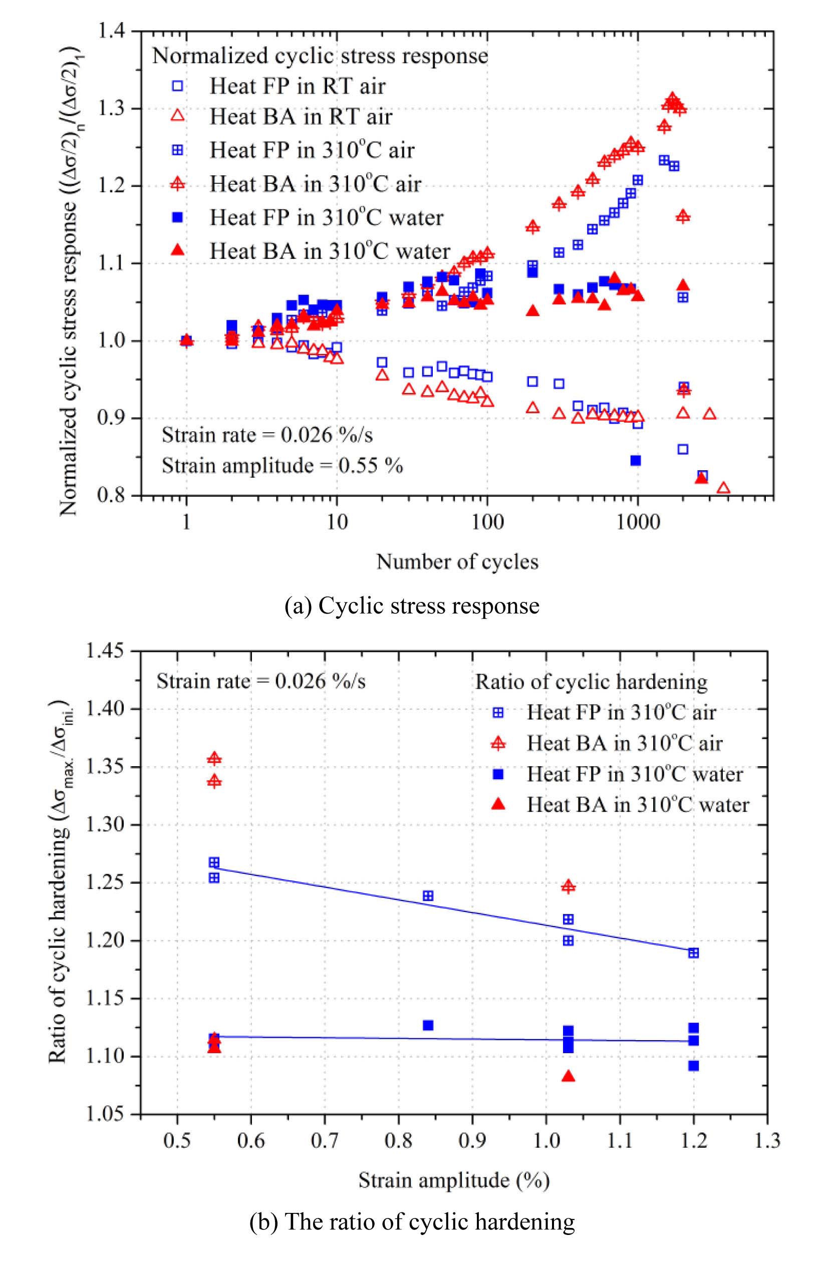
Fig. 8 shows the normalized cyclic stress (((∆σ/2)n) / ((∆σ/2)1) behaviors and the ratio of cyclic hardening ((∆σmax) / (∆σini)) [9]. It was well accepted that the occurrence of DSA could be manifested by increase in strength, negative strain rate sensitivity, and serrated flow of stress-strain
curves [11]. Among these, the hardening of cyclic stress at high temperature could be one of the clear evidences of DSA, and cyclic hardening could be enhanced with an occurrence of DSA [12,13]. Based on cyclic stress behaviors, it was found that heat BA showed higher degree of cyclic hardening than heat FP in 310 ℃ air, but both heats showed similar cyclic hardening behaviors in 310 ℃ deoxygenated water. Therefore, it was thought that the degree of DSA was higher for heat BA than heat FP in 310 ℃ air. On the other hand, in 310 ℃ deoxygenated water, the degree of DSA was diminished and the difference of degree of DSA between the two heats was negligible as shown in Fig. 8.
As mentioned above, the LCF life of LASs in 310 ℃ deoxygenated water is affected by hydrogen [8]. Because hydrogen is known to play the role of a softener in the DSA temperature range [14,15], it could be closely related to the reduction of the cyclic stress in 310 ℃ deoxygenated water. Because of the higher mobility of hydrogen than interstitial atoms, such as carbon and nitrogen, hydrogen could prevent the interaction of carbon and nitrogen with dislocations [14]. Also, the softening is possible when sufficient micro-voids are developed due to hydrogen during deformation [15]. Consequently, the absorbed hydrogen would interact with both dislocations and micro-voids at 310 ℃, which then would cause softening and reduce the degree of DSA as shown in Fig. 8. It is well known that the DSA could decrease the LCF life because of the local deformation inhomogeneity and larger stress concentration at the crack tip [16,17]. Also, showing a higher degree of DSA, the LCF life of heat BA in 310 ℃ air was expected to be shorter than that of heat FP. However, the LCF life of heat BA was similar to that of heat FP in 310 ℃ air as shown in Fig. 7 (a). The differences in microstructure could have affected the LCF life of two heats as described below [7].
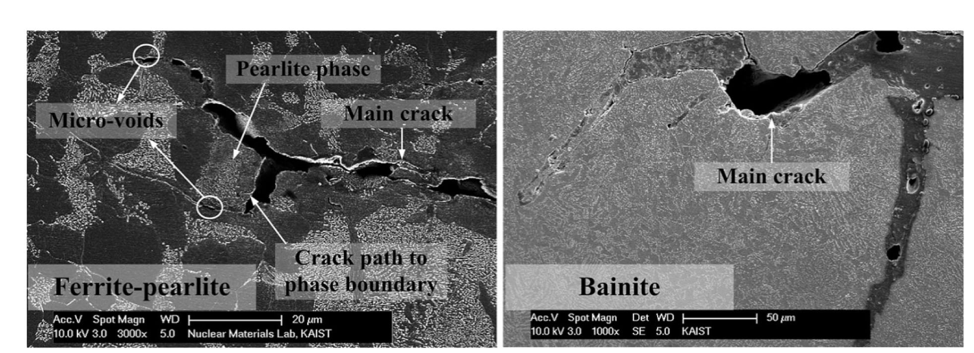
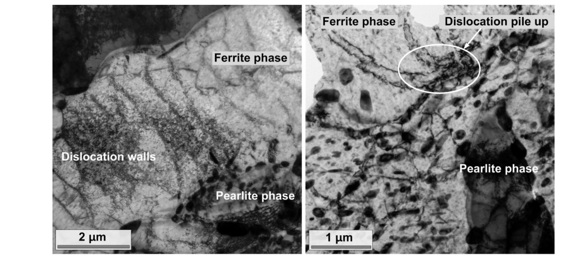
Fig. 9 shows the sectioned view of the fatigue cracks of the two heats tested in 310 ℃ deoxygenated water. The crack of heat FP was propagated along ferrite and ferritepearlite phase boundary while that of heat BA was propagated through randomly-distributed carbides in a bainite structure. From the observation of dislocation morphologies near the crack tip as shown in Fig. 10 [7], the dislocation wall structure and pile up of dislocations in ferrite phase were observed while the tangled dislocations were occasionally observed in the pearlite phase. These different dislocation morphologies could indicate that the plastic deformation was localized in the ferrite adjacent to the pearlite and thereby increase the localized stress at the ferrite-pearlite interface. Thus, the fatigue crack growth along the ferrite-pearlite phase boundaries could be accelerated by the stress concentration effects. Mediratta also reported that the resistance of a barrier can be very low when the fatigue cracks were propagating along the phase boundaries due to the local plastic deformation [18]. Therefore, a shorter LCF life of heat FP resulted from the lower resistance of the ferrite-pearlite microstructure for the LCF
crack propagation. As a consequence, in 310 ℃ air, where the effect of DSA was large enough to override the microstructure effect, the LCF life of heat BA was similar to that of heat FP. On the other hand, the LCF life of heat BA was longer than that of heat FP in 310 ℃ deoxygenated water, where the difference of DSA was not significant for both heats [7].
4. ENVIRONMENTAL FATIGUE BEHAVIORS OF STAINLESS STEELS
4.1 LCF Behaviors of Type 316LN
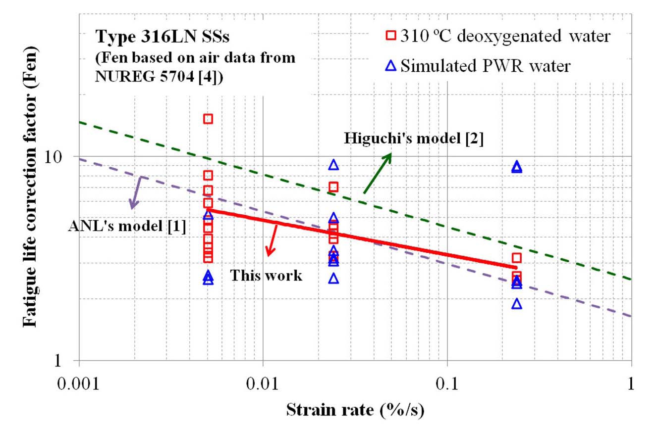
Fig. 11 shows the fatigue life correction factor (Fen) of 316LN SSs calculated from the LCF test at 310 ℃ water environments. As RT data are insufficient, RT test data of 316NG SS in NUREG/CR-5704 were used in the calculation of Fen values [4]. Overall, Fen values at 310 ℃ are similar in deoxygenated and simulated PWR water environments. As shown in the figure, the LCF life in 310 ℃ water decreased by a factor of 2 ~ 10 compared to that in RT air, which decreased with increasing strain rate. The Fen values measured from our LCF data were similar to the prediction models, such as ANL [1] and Higuchi [2].
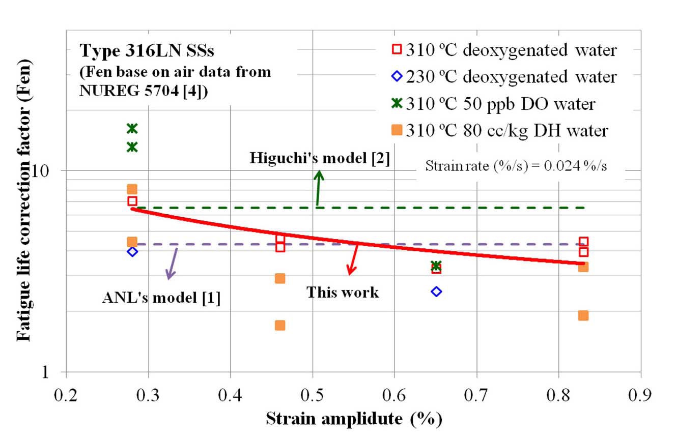
In Fig. 12, additional test data at a lower temperature (230 ℃), at a higher DO level (50 ppb), and at a high DH level (80 ppb) are plotted. As expected from the models [1,2], Fen values decreased at lower temperature. Meanwhile, Fen values increased at a higher DO level at a lower strain amplitude, which was not consistent with the model prediction. Also, Fen values were somewhat lower at a high DH
level. Both experimental observations were based on limited test data, and thereforel tests and analysis are needed to verify such behaviors.
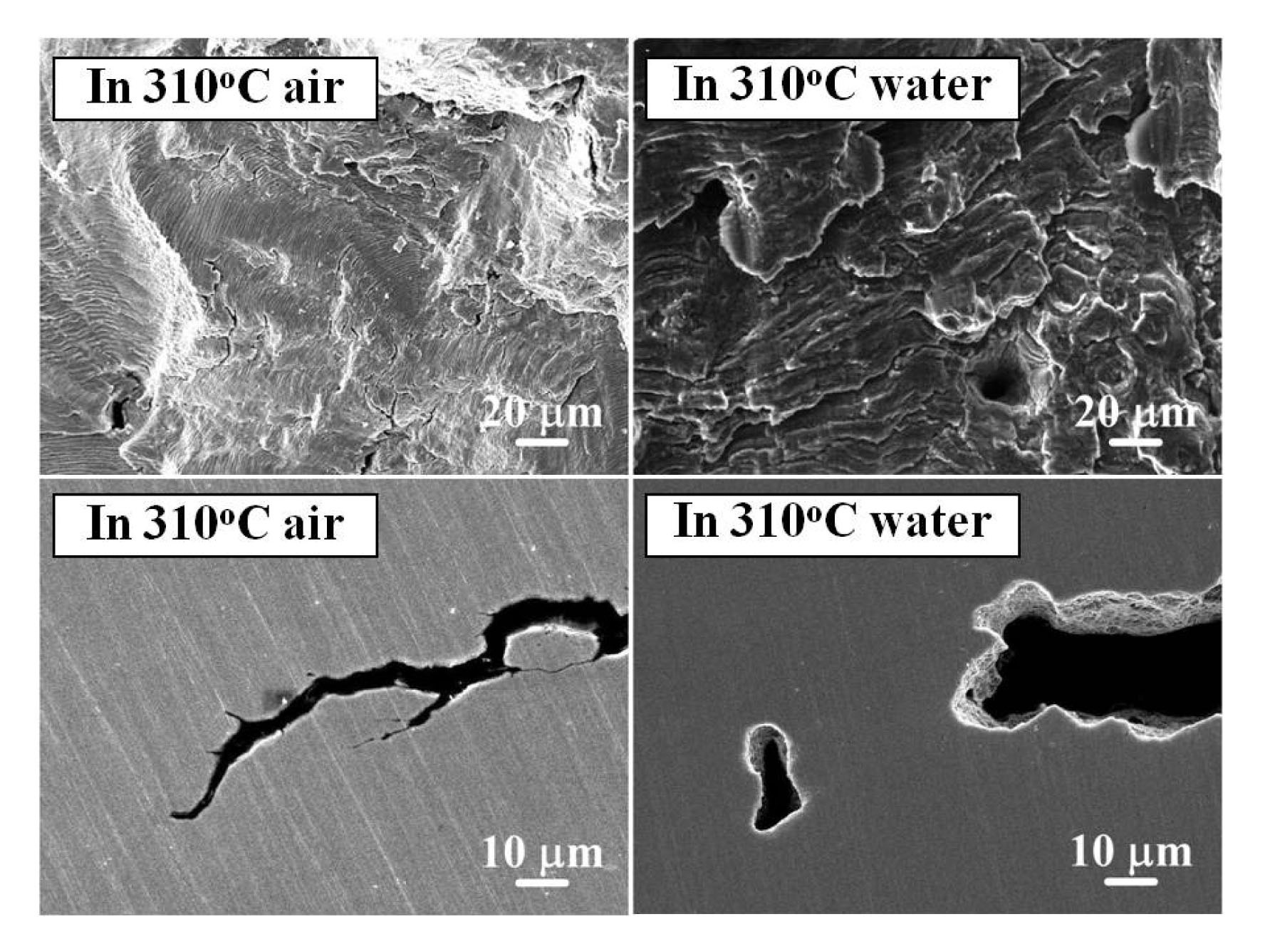
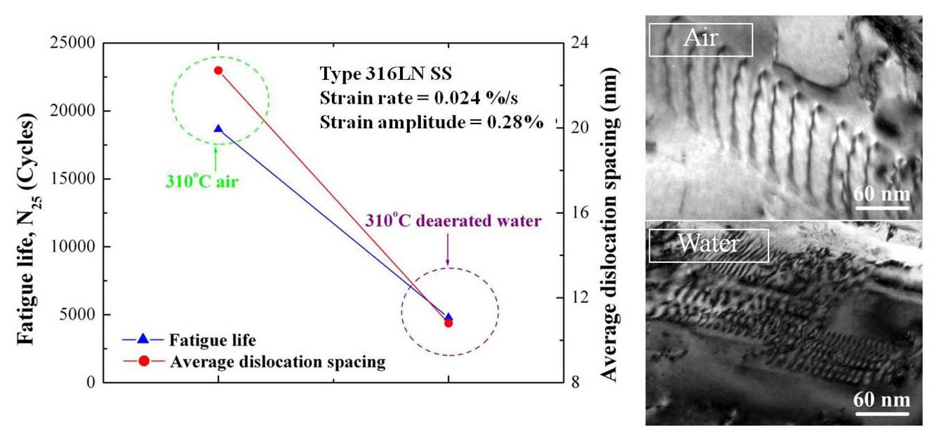
Fig. 13 shows the fatigue surface and sectioned fatigue cracks tested in 310 ℃ air and deoxygenated water. In both specimens tested in 310 ℃ air and deoxygenated water, the striations were observed at below 1000 µm from the fatigue crack initiation site. The streamed down features and crack blunting shape were observed on the specimens tested in 310 ℃ deoxygenated water. However, despite of these evidences, well-defined striations were still observed on the fatigue surfaces of the specimens tested in 310 ℃ deoxygenated water. Therefore, it is thought that the metal dissolution is not an active EAC mechanism. However, some evidences for the HIC were also found in the sectioned fatigue crack tested in 310 ℃ deoxygenated water such that the micro-void ahead of the main crack and their tendencies of coalescence into the main crack were observed [19]. Furthermore, as shown in Fig. 14, the dislocation spacing in 310 ℃ deoxygenated water was narrower than that in 310 ℃ air under the same loading conditions. Also, the LCF life of 316LN SS decreased with reduction in the average dislocation spacing in 310 ℃ deoxygenated water.
It is reported that the absorbed hydrogen could reduce the dislocation spacing and enhancing the mobility of dislocations by reducing the repulsive forces between the dislocations [9,10]. As a consequence, the absorbed hydrogen could accelerate the fatigue crack growth rate. Therefore, it is thought that the HIC is the main EAC mechanism for the reduction in the fatigue life of the type 316LN SS in high-temperature deoxygenated water while the effect of the metal dissolution is less significant [19,20].
4.2 Comparison of LCF Behaviors of Type 316LN and CF8M SSs
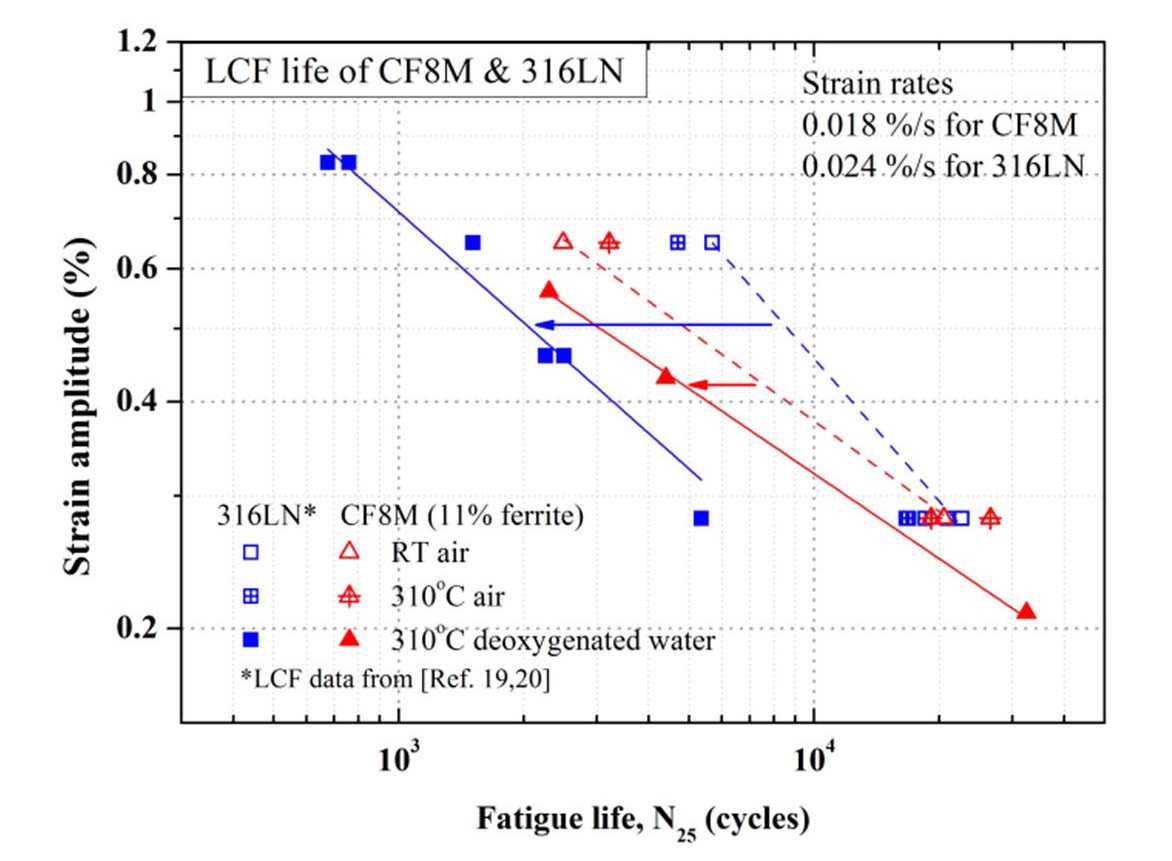
In Fig. 15, the LCF life of 316LN and CF8M SSs are compared. Our test results showed that the reduction ofife of CF8M in 310 ℃ deoxygenated water was smaller than that of 316LN. On the other hand, Higuchi reported that the Fen value of both wrought and cast SSs were similar in simulated PWR environment [2]. However, in Higuchi’s study, the Fen value of cast stainless steels was calculated by Tsutsumi’s model which was based on LCF data of wrought SSs in RT air [21]. We carefully extracted the LCF data of cast stainless steels produced in RT air and 310 ℃ deoxygenated water and re-plotted the Fen value of cast SSs. The Fen value was smaller than
that of wrought SSs in simulated PWR environment, which is similar to our test data [22].
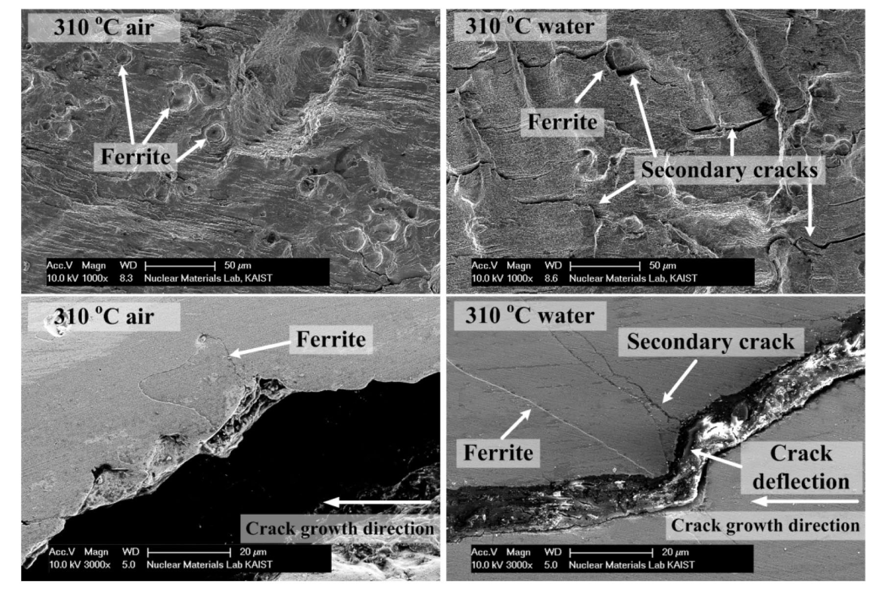
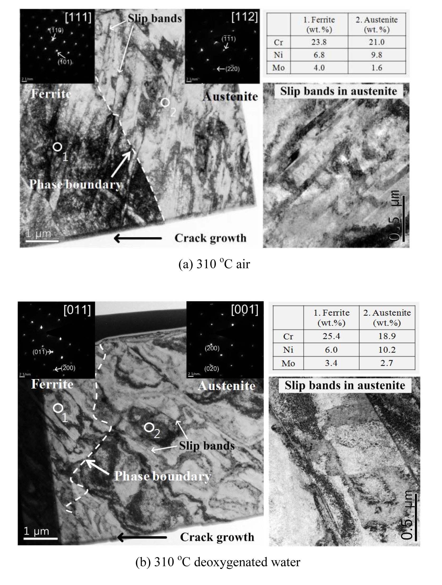
Fig. 16 shows the fatigue fracture morphologies of CF8M tested in 310 ℃ air and deoxygenated water. Fatigue striations were well observed on the fatigue surfaces tested in both environments. On the other hand, the number of secondary cracks was markedly increased in specimens tested in 310 ℃ deoxygenated water as shown in Fig. 16. The secondary cracks were developed in the austenite phase or ferrite-austenite boundaries. Fig. 17 shows the planar slip bands with dislocations of CF8M tested in 310 ℃ air and deoxygenated water. The planar slip bands were observed in the austenitic phases of both specimens tested in 310 ℃ air and deoxygenated water, but the number of planar slip bands in 310 ℃ deoxygenated water was smaller than those in 310 ℃ air. It was reported that the plastic deformation is concentrated along the planar slip bands where the slip planarity is observed [23]. Therefore, the relatively few planar slip bands observed in 310 ℃ deoxygenated water would indicate that the plastic deformation was more localized and concentrated at relatively few
slip bands. Furthermore, because the absorbed hydrogen accelerates the localization of slip bands [9,10], the localization of plastic deformation and subsequent micro-cracking could be enhanced by absorbed hydrogen. Therefore, like SA508 Gr. 1a [8] and 316LN [19,20], the LCF life of CF8M was mainly affected by the environmental factor during LCF processes in 310 ℃ deoxygenated water [22].
As shown in Fig. 16, in 310 ℃ deoxygenated water, when the fatigue crack was confronted with the ferrite phase, the fatigue crack would be branched by the formation of a secondary crack in the austenite phase, and then deflected along the ferrite–austenite boundary. As mentioned above, because the secondary cracks could be easily formed at the ferrite–austenite interfaces by operation of the HIC mechanism, it could effectively reduce the stress concentration at the crack tip due to crack branching. Because it is well known that the micro-structurally small crack is significantly affected by a barrier role of relatively high hardness phases [1], similar effects could be operated in fatigue crack growth process with multiple cracking. Therefore, the fatigue crack growth would be retarded by a barrier role of ferrite phase in CF8M, especially8451; deoxygenated water although the HIC mechanism is still operated in the LCF process at the same time [22].
5. ENVIRONMENTAL FATIGUE BEHAVIORS OF NICR-FE ALLOYS
5.1 LCF Behaviors of Alloy 690 and 52M Welds
The Ni-Cr-Fe alloys and related welds have been used as structural materials such as RPV CRDM nozzle, BMI nozzle, and dissimilar metal welds, etc. Though, Ni-Cr-Fe alloys are grouped with stainless steels in the ASME fatigue design curves, they are treated separately in the calculation of fatigue life correction factor, Fen, since the issuance of RG-1.207 [5]. However, the limited fatigue life data were used to develop the Fen for Ni-Cr-Fe alloys [1,24]. Furthermore, the test data for Alloy 690 and its welds are limited. Considering that Alloy 690 and 52/152 welds are extensively used in the new nuclear power plants including APR 1400, additional efforts to validate or improve current Fen model are required. To resolve these problems, an environmental fatigue test for these materials was performed and the new prediction model of fatigue life of Alloy 690 and 52M weld in primary water condition was proposed.
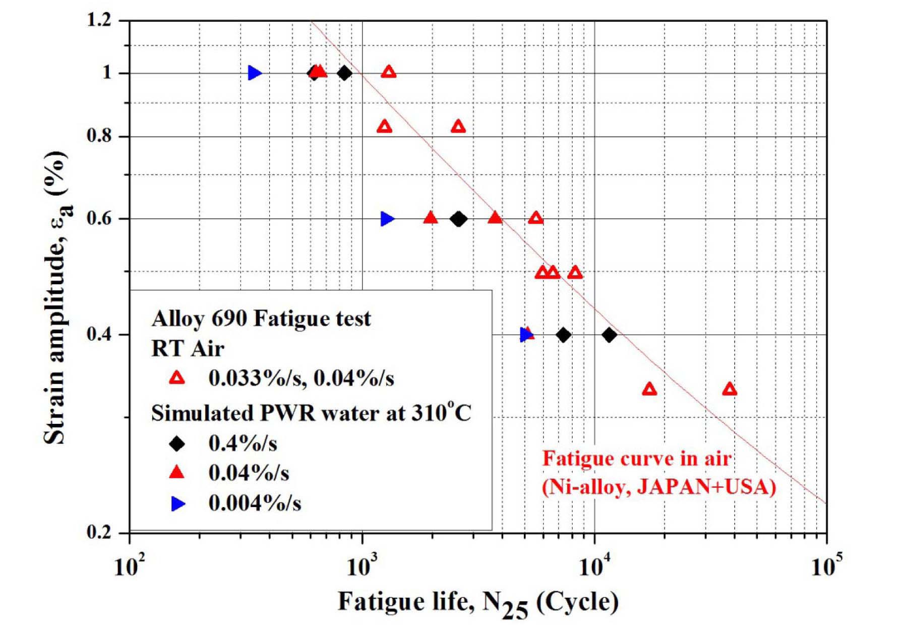
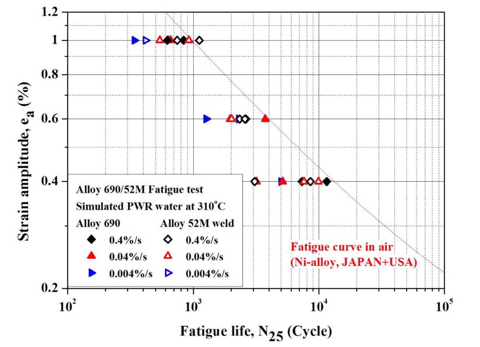
Fig. 18 shows the LCF life of Alloy 690 in simulated PWR environment. For comparison, fatigue life model for Ni-base alloy of JSME, ASME code mean curve, and fatigue design curve as well as the prediction model of ANL for stainless steels are also shown. The LCF life decreased in a simulated PWR environment in comparison with that in RT air condition. The LCF life decreased with decreasing strain rate which are similar results to those of SA508 Gr.1a and 316LN. Therefore, it is thought that the LCF life of Alloy 690 may still be affected by EAC mechanisms. However, the degree of reduction in fatigue life was smaller than other structural materials, such as LAS, and SSs. Also, the overall test results are similar to published data and are in good agreement with existing prediction models by ANL [1] and Higuchi [2], although
there are some scatters on the data of 0.04%/s. The tested fatigue life data of Alloy 690 and 52M are compared in Fig. 19. As shown in the figure, the fatigue lives of 52M weld are comparable with those of Alloy 690.
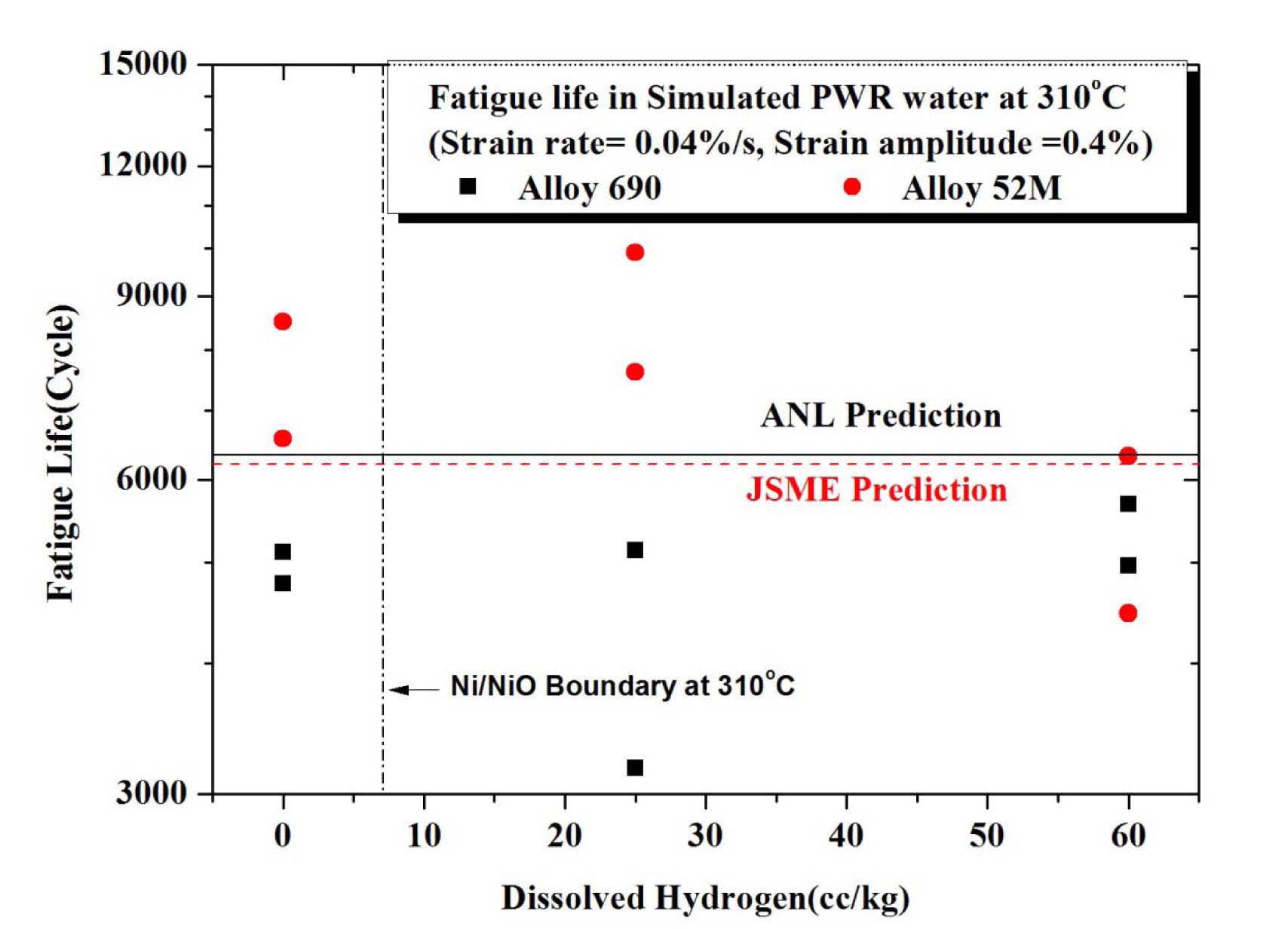
Additionally, the effect of DH level on low cycle fatigue life was also investigated. The DH level was controlled from 0 cc/kg to 60 cc/kg. Fig. 20 shows the limited test results with varying DH level on the LCF life of Alloy 690 and 52M weld in a simulated PWR environment. As shown in the figure, the dissolved hydrogen has no distinct effect on the LCF life of Alloy 690 and 52M weld in PWR environment.
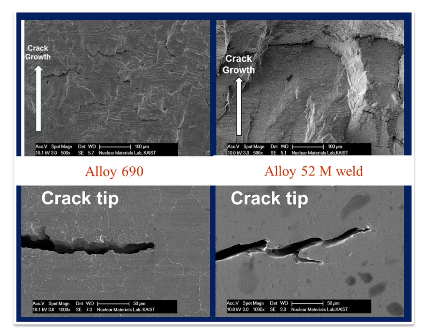
Fig. 21 shows the fatigue surface and sectioned fatigue cracks of Alloy 690 and 52M weld specimens tested in a simulated PWR environment. On the fatigue surfaces, the crack blunting with wide crack opening were observed as in the case of 316 LN SS, which would suggest the presence of metal dissolution [19]. However, as the well-developed ductile striations were observed on the fatigue surfaces,
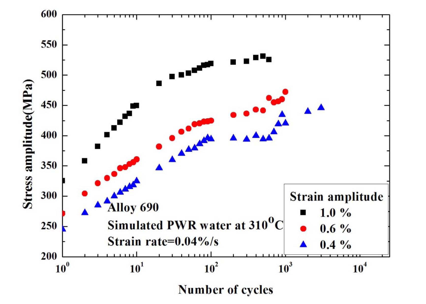
the metal dissolution alone may not be sufficient to explain the reduction in the fatigue life of these alloys in a simulated PWR environment. Alloy 690 shows rapid hardening behaviors during the first 40~100 cycles, and followed by continuous softening behaviors in RT air environment. Meanwhile, unlike LASs and SSs which showed less cyclic hardening in high temperature water environments, Alloy 690 and 52M showed a rather persistent cyclic hardening until the test was terminated as shown in Fig. 22. As cyclic hardening is known to be related to the DSA, which would partly contribute to the reduction of fatigue life in high temperature water environment, the lower Fen values of Alloy 690 than 316LN seem contradictory. One possible explanation is that as better corrosion resistance of Alloy 690 would have produced less hydrogen in the crack tip, the HIC mechanism could have been suppressed for the fatigue cracks. However, a more detailed analysis is needed to understand the LCF behaviors of Ni-Cr-Fe alloys in high temperature water environments.
5.2 Development of the Revised Fen Model for Alloy 690 and 52M Weld
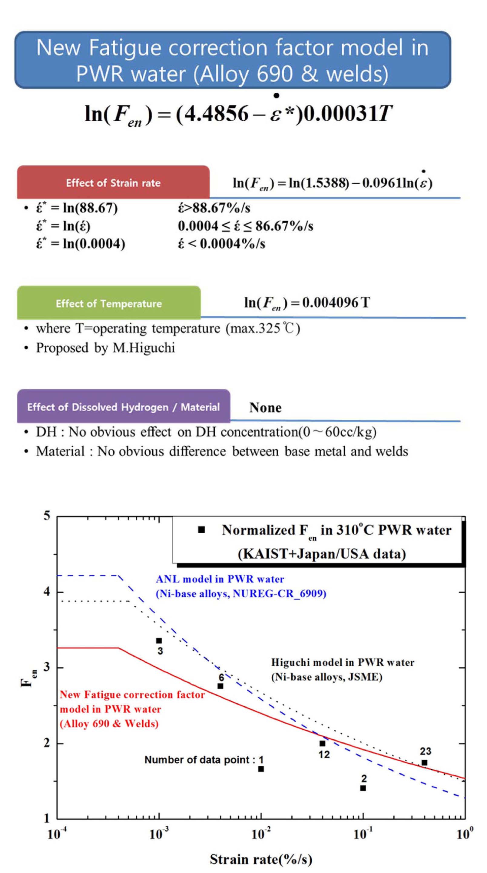
As mentioned before, the existing prediction models (ANL and Higuchi) are based on the limited database mainly consists of Alloy 600 and its welds. As it is certain that those materials will no longer be used for the design and construction of new reactors, such as APR 1400, development of a separate Fen model for Alloy 690 and 52M weld seems more appropriate. Thus, we tried to develop a revised model for Alloy 690 and 52M by adding our data to the existing database of ANL and Higuchi’s [1,2]. The revised prediction model consists of a new fatigue curve in air environment and Fen model for a simulated PWR environment. Fig. 23 shows the details of the revised prediction model considering parameters like strain rate,
[Table 4.] Estimated Scatter of Fatigue Life Prediction of Alloy 690 and 52M by Various Model [25]
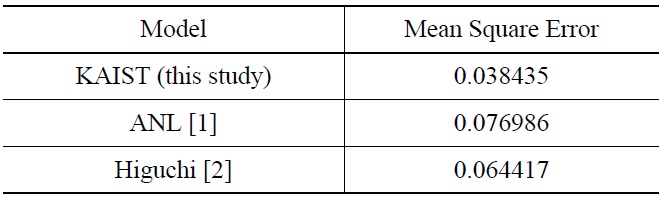
Estimated Scatter of Fatigue Life Prediction of Alloy 690 and 52M by Various Model [25]
temperature, and dissolved hydrogen concentration. It should be noted that, in the revised model, we used the general equation form used by ANL. With the revised Fen model for Alloy 690 and 52M, the scatter of the fatigue life prediction has been reduced as shown in Table 4, indicating that the revised model will be more reliable in environmental fatigue evaluation.
6. ON-GOING ACTIVITIES RELATED TO ENVIRONMENTAL FATIGUE
6.1 Environmental Fatigue Test Plan for Hot-bent 347 SS for Surgeline Application
The pressurizer surge line made of stainless steels is one of most susceptible components to environmental fatigue due to high stress caused by thermal stratification and operational transients. Consequently, it is difficult to satisfy the fatigue design requirement, or cumulative usage factor<1.0, if the high Fen values of RG.1-207 are applied, especially for the welds and bends where stress concentration is typically high. As an alternative method to solve the problem, a large radius hot-bending method has been adopted to eliminate some weld joints and all tight bends for some of the advanced reactors. However, as hot-bending involves a high temperature thermal cycle, there is a concern about the possible changes in microstructure and mechanical properties including the environmental fatigue properties in a PWR environment. In addition, unlike other reactors which typically use Type 316 SS for surgeline pipes, APR 1400 adopted Type 347 SS which was not properly represented in U.S and Japanese environmental fatigue test programs. Therefore, to verify the applicability of hot-bending on 347 SS surgeline pipes, an environmental fatigue test program for these materials was initiated.
As shown in Fig. 24, specimens from five different locations, extrados, middle, and intrados of bent pipe, as-received pipe, and heat-affected zone, will be included in the environmental fatigue test program. Additionally, the environmental fatigue behaviors of hot-bent 347 SS in PWR environment will be compared with 316 SS which was widely represented in foreign test programs. Test results from this program could provide the technical basis for resolving the environmental fatigue issue and licensing of hot-bending methods on the surgeline pipes.
Environmental fatigue of the metallic components in light water reactors has been the subject of extensive research and regulatory interest in Korea and abroad. Especially, it was one of the key domestic issues concerning the license renewal of operating reactors and licensing of advanced reactors during the early 2000s. To deal with the environmental fatigue issue domestically, a systematic test program was initiated and is still underway. The key results obtained through the test program and subsequent analysis can be summarized as follows:
1. In high temperature water environments, the LCF life of SA508 Gr.1a LAS and type 316LN SS decreased by EAC mechanisms. The metal dissolution and HIC mechanisms are mainly responsible for the reduction of the LCF life of SA508 Gr.1a LAS. While, the LCF life of 316LN SS in 310 ℃ deoxygenated water decreased mainly by the HIC mechanism.
2. The LCF behaviors of SA508 Gr.1a were dependent on their microstructures and dynamic strain aging susceptibility. The LCF life of heat FP with ferritepearlite microstructure was shorter than that of heat BA of bainite microstructure in 310 ℃ deoxygenated water where DSA was not so significant and therefore, the microstructure effect was dominant. Meanwhile, in 310 ℃ air, where the effect of DSA was large enough to override the microstructure effect, LCF life of heat BA was similar to that of heat FP. However, the effect of microstructure and DSA on LCF life of two heats of SA508 Gr.1a were based on a limited amount of test data. Thus, additional LCF tests are needed to clarify the microstructure effect on LCF life.
3. The LCF life of Alloy 690 and 52M in a simulated PWR environment was shorter than that in RT air, but the reduction of LCF life is considerably smaller than that of austenitic SS. Additionally, revised fatigue life prediction models and fatigue life correction factor for Alloy 690 and 52M were proposed using accumulated test data. A more detailed analyses will be performed to understand the LCF behaviors of Ni-Cr-Fe alloys in a simulated PWR environment.


![The Fatigue Surfaces and Sectioned Fatigue Crack of SA508 Gr.1a ? heat FP in RT Air and 310 ℃ Deoxygenated Water [8]](http://oak.go.kr/repository/journal/12950/OJRHBJ_2013_v45n7_929_f006.jpg)
![The LCF Life of Two Heats of SA508 Gr.1a in; (a) RT and 310 ℃ air, (b) 310 ℃ Deoxygenated Water [7]](http://oak.go.kr/repository/journal/12950/OJRHBJ_2013_v45n7_929_f007.jpg)
![Normalized Cyclic stress Responses of Two Heats of SA508 Gr.1a; (a) Cyclic Stress Response, (b) The Ratio of Cyclic Hardening [7]](http://oak.go.kr/repository/journal/12950/OJRHBJ_2013_v45n7_929_f008.jpg)
![The Sectioned Fatigue Cracks of Two Heats of SA508 Gr.1a Tested in 310 ℃ Deoxygenated Water [7]](http://oak.go.kr/repository/journal/12950/OJRHBJ_2013_v45n7_929_f009.jpg)
![Dislocation Morphologies below the Fatigue Surface of Heat FP of SA508 Gr.1a [7]](http://oak.go.kr/repository/journal/12950/OJRHBJ_2013_v45n7_929_f010.jpg)


![The Fatigue Surfaces and Sectioned Fatigue Cracks of Type 316LN SS in 310 ℃ Air and Deoxygenated Water Environments [19]](http://oak.go.kr/repository/journal/12950/OJRHBJ_2013_v45n7_929_f013.jpg)
![Relationship of LCF Life with Dislocation Spacing [20]](http://oak.go.kr/repository/journal/12950/OJRHBJ_2013_v45n7_929_f014.jpg)
![Comparison of LCF Life of CF8M and 316LN SSs [22]](http://oak.go.kr/repository/journal/12950/OJRHBJ_2013_v45n7_929_f015.jpg)
![Fatigue Surfaces and Sectioned Fatigue Cracks of CF8M SS in 310 ℃ air and Deoxygenated Water Environments [22]](http://oak.go.kr/repository/journal/12950/OJRHBJ_2013_v45n7_929_f016.jpg)
![Planar Slip Bands in the Austenite Phase Adjacent to the Ferrite Phase of CF8M Tested in; (a) 310 ℃ Air, (b) 310 ℃ Deoxygenated Water [22]](http://oak.go.kr/repository/journal/12950/OJRHBJ_2013_v45n7_929_f017.jpg)
![LCF Life of Alloy 690 in RT Air and Simulated PWR Environments [25]](http://oak.go.kr/repository/journal/12950/OJRHBJ_2013_v45n7_929_f018.jpg)


![Revised Fatigue Life Correction Factor Model in PWR Water for Alloy 690 and 52M weld [25]. Number of Data Points is Shown on the Measured Fen Data.](http://oak.go.kr/repository/journal/12950/OJRHBJ_2013_v45n7_929_f023.jpg)
![Estimated Scatter of Fatigue Life Prediction of Alloy 690 and 52M by Various Model [25]](http://oak.go.kr/repository/journal/12950/OJRHBJ_2013_v45n7_929_T004.jpg)