The concept of fault tolerance has become increasingly important during the past decades because of the increased use of computers in many aspects of almost everyone’s life [1]. A fault is a defect in the hardware or software that can lead to an incorrect state. In most cases, a fault first causes an error in the service state of a component, and the external output state is not immediately affected. Faults can result in errors, and errors are liable to eventually cause system failures. The primary goal of fault tolerance is to prevent errors from leading to system failure [2].
The safety I&C systems in nuclear power plants have been designed to perform the safety functions required for a design basis event (DBE) in the presence of the following: a) any single detectable failure within the safety systems concurrent with all identifiable but non-detectable failures, b) all failures caused by a single failure, and c) all failures and spurious system actions that cause, or are caused by, the DBE requiring the safety function [7]. This singlefailure criterion has been applied for the fault-tolerant capability of safety grade I&C equipment.
The safety I&C system is required to perform its safety function to maintain plant parameters within acceptable limits established for a DBE, regardless of any singlefailure occurring within the system [9]. In addition, the safety I&C system should be designed to prevent a spurious actuation, because the spurious actuation of a reactor trip or an ESF actuation can cause a threat to public welfare. Therefore, the plant protection system (PPS) has been designed with hardware redundancy of four independent channels with 2-out-of-4 coincidence logic.
Common-cause failure (CCF) means the loss of function to multiple structures, systems, or components due to a shared root cause [15]. The CCF includes those that can result from external environmental effects, design deficiencies, manufacturing errors, maintenance errors, and operator errors [7]. Digital I&C systems can be vulnerable to CCFs caused by software errors or software developed logic, which could defeat the redundancy achieved by the hardware architecture [9]. Therefore, diversity and defensein-depth (D3) has become an important issue to overcome the CCF of the safety I&C systems.
The diverse protection system (DPS) has been provided to mitigate an anticipated transient without scram (ATWS) and common cause failures (CCF) of safety I&C systems of Advanced Power Reactor 1400 (APR1400) nuclear units in Korea [3]. The major protection system in the APR1400 is the safety-grade PPS. The DPS, a non-safety system, provides partial back-up means to the PPS, and it provides diverse methods to trip the reactor, and also to provide some engineered safety feature (ESF) functions to satisfy the ATWS and CCF requirements [4&5].
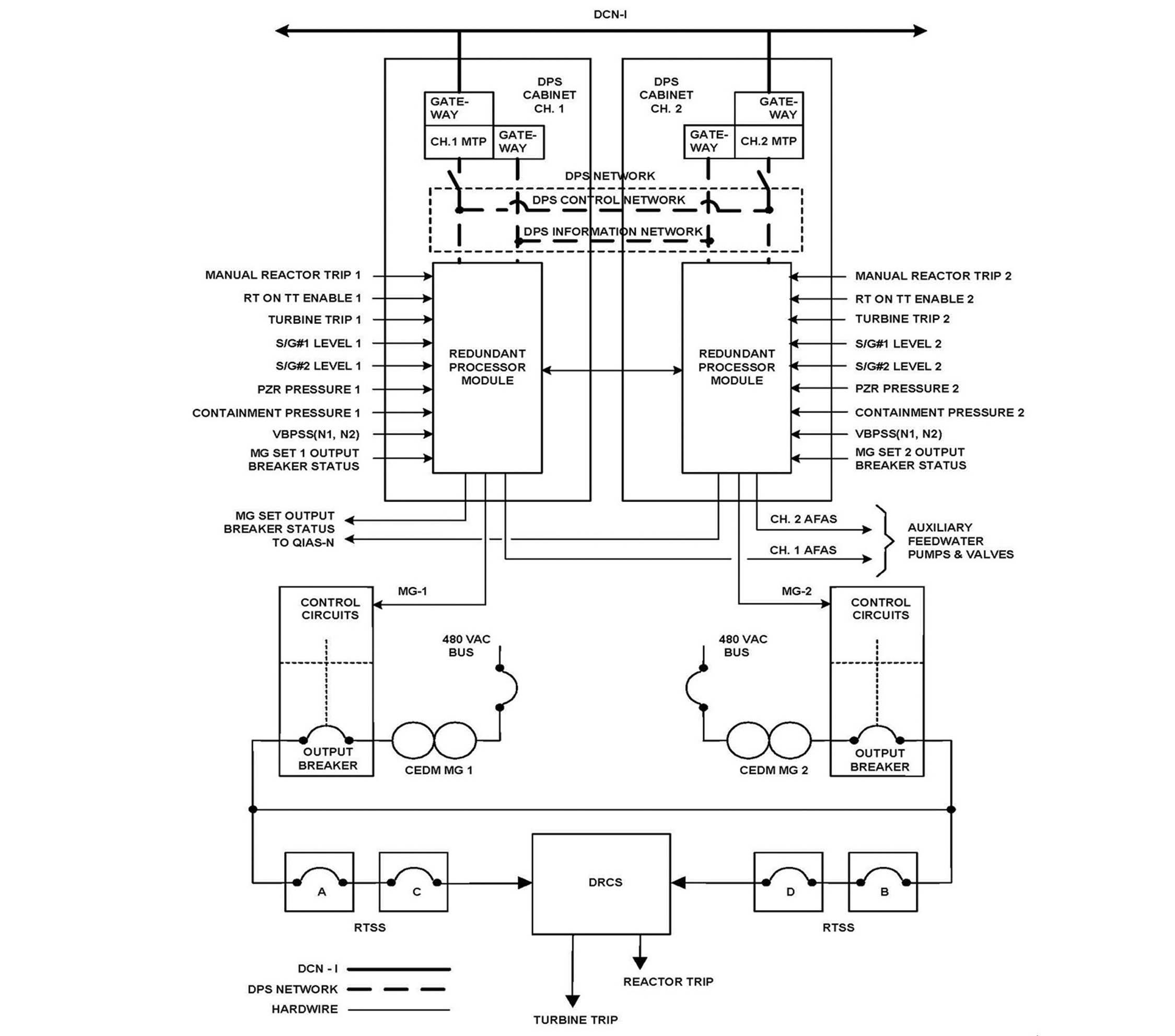
All the Optimized Power Reactor 1000 (OPR1000) and the APR1400 nuclear units in Korea have been designed with the DPS, which has the diverse reactor trip function and the diverse auxiliary feedwater actuation signals (AFAS) initiation function for the engineered safety feature ? component control system (ESF-CCS) [6]. As shown in Figure 1, the DPS for the APR1400, which includes Shin- Kori nuclear units 3 and 4 (SKN 3&4) and Shin-Hanul nuclear units 1 and 2 (SHN 1&2), has been designed as a non-safety system with two channels, and is not required to meet the single failure criterion.
All OPR1000 and APR1400 nuclear units currently have a DPS with two (2) channels. Using the 2-out-of-2 (2/2) coincidence logic, the DPS shown in Figure 1 can prevent any spurious reactor trip or AFAS initiations. However, the failure of one major DPS component can directly cause a system failure as illustrated in the DPS reliability block diagram of Figure 4. Therefore, the DPS with a 2/2 coincidence logic can hardly be fault-tolerant, because it does not have any redundant channels [12]. Considering fault tolerance issues, and the system development situations of domestic and foreign diverse actuation systems (DAS), the ADPS channel configuration has been changed such that it has four (4) channels with the 2/4 coincidence logic.
During the design process of the new DPS regarding the D3 issues, the fault tolerance capability of the DPS has been discussed. KEPCO E&C has designed a new DPS, which is named the Advanced DPS (ADPS), to enhance its fault-tolerant capability and to consider the application of the single failure criterion to the extent practically feasible.
Fault tolerance techniques enable a system to tolerate misbehaviors occurring during operation. Effective and complementary fault tolerance approaches incorporate fault
detection, fault containment, fault masking, safe fallback, fault recovery, and signaling of misoperation [8].
The ADPS design illustrated in Figure 2 accommodates the following fault tolerance and fault avoidance design features:
? Fault masking capability with redundant four (4) channels using the 2-out-of-4 (2/4) voting logic,
? Fault masking capability with redundant actuation devices, including two (2) sets of reactor trip switchgear systems (RTSS),
? Fault avoidance capability based on the changes of software class, communication, and man-machine interface (MMI).
? CCF avoidance with the application of diverse equipment platform for the ADPS compared with that for the PPS.
? The use of Class 1E process instrumentation (PI) sensors and the RTSS for the DPS input and output interfaces will contribute to the fault avoidance capability of the system, because the equipment qualification and overall reliability levels of the Class 1E sensors and reactor trip actuation devices are higher than those of non-Class 1E equipment,
? Fault detection and location capability based on the system trouble alarms and watch dog timers, and
? Fault containment and recovery support capability based on manual channel bypass, and maintenance support for the replacement of faulty equipment.
2. ADPS DESIGN FEATURES FOR FAULT MASKING
The ATWS rule of 10 CFR 50.62 allows the DPS to be a non-safety system if the system is of sufficient quality to perform the necessary functions under the associated event conditions [4&11]. The DPS for the APR1400 has two identical channels as depicted in Figure 3.
To prevent an inadvertent DPS actuation, the DPS reactor trip is performed by the 2/2 voting logic within each DPS channel, and the 2/2 actuation logic of the MG set output breakers.
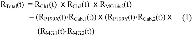
Figure 4 shows the reliability block diagram (RBD) for the DPS reactor trip caused by high pressurizer pressure. Because of the 2/2 voting logic in each channel and the 2/2 actuation logic of the final actuation devices, all of the blocks [i.e., two sensors (P-199X & P-199Y), all of the related signal processing equipment in both DPS CH. 1 and 2 cabinets, and both MG Set 1 and 2 breakers] should normally function to maintain overall system operability. Therefore, the RBD of Fig. 4 shows that all the related blocks are connected in series for the system function, even though two DPS channels are physically configured in parallel as shown in Figure 3.
Using the RBD of Fig. 4, the DPS reliability [RTotal(t)] and average failure rate [λTotal] can be expressed as:
Where the following are assumed:
1) System components are operated in the constant failure rate region,
2) Failure rates of both DPS channels are the same, and
3) Failure rates of both MG sets are the same.
λCh1 = λCh2 = λCh, λMG1 = λMG2 = λMG
RTotal(t) = RCh1(t)·RCh2(t)·RMG1(t)·RMG2(t) = e -λCh1·t e -λCh2·t e -λMG1·t e -λMG2·t = e -(λCh1 + λCh2 + λMG1 + λMG2)·t = e -λTotal·t
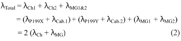

Based on Eq. (2), we find that the RBD of Figure 4 indicates a doubled failure rate compared with a single channel case.
The DPS for APR1400 has the fault-tolerant features of power supplies (feed from two power sources) and controller CPU modules. But, the APR1400 DPS has an overall limitation of fault tolerance as shown in Figure 2. Any fault or failure within one block in Figure 2 can cause the consequential failure of the system. In addition, the DPS function for the APR1400 is temporally stopped when one channel output is bypassed for maintenance and/or a system test.
There has been no licensing requirement of singlefailure criterion for the DPS. But, the ADPS has been designed to equip four channels with 2/4 voting logic for the fault tolerance capability. Major reasons of the four channel redundancy of the ADPS are as follows:
? At least two channels are required for the 2/4 voting logic to prevent any spurious trip actuations,
? One faulted channel can be bypassed during a prolonged period of maintenance,
? One tested channel should be bypassed during the automatic system test period,
? With the four channels of redundancy, the system can tolerate up to two channels of simultaneous faults, and
? As an overall result, the availability of the system can be drastically enhanced by the use of four channels.
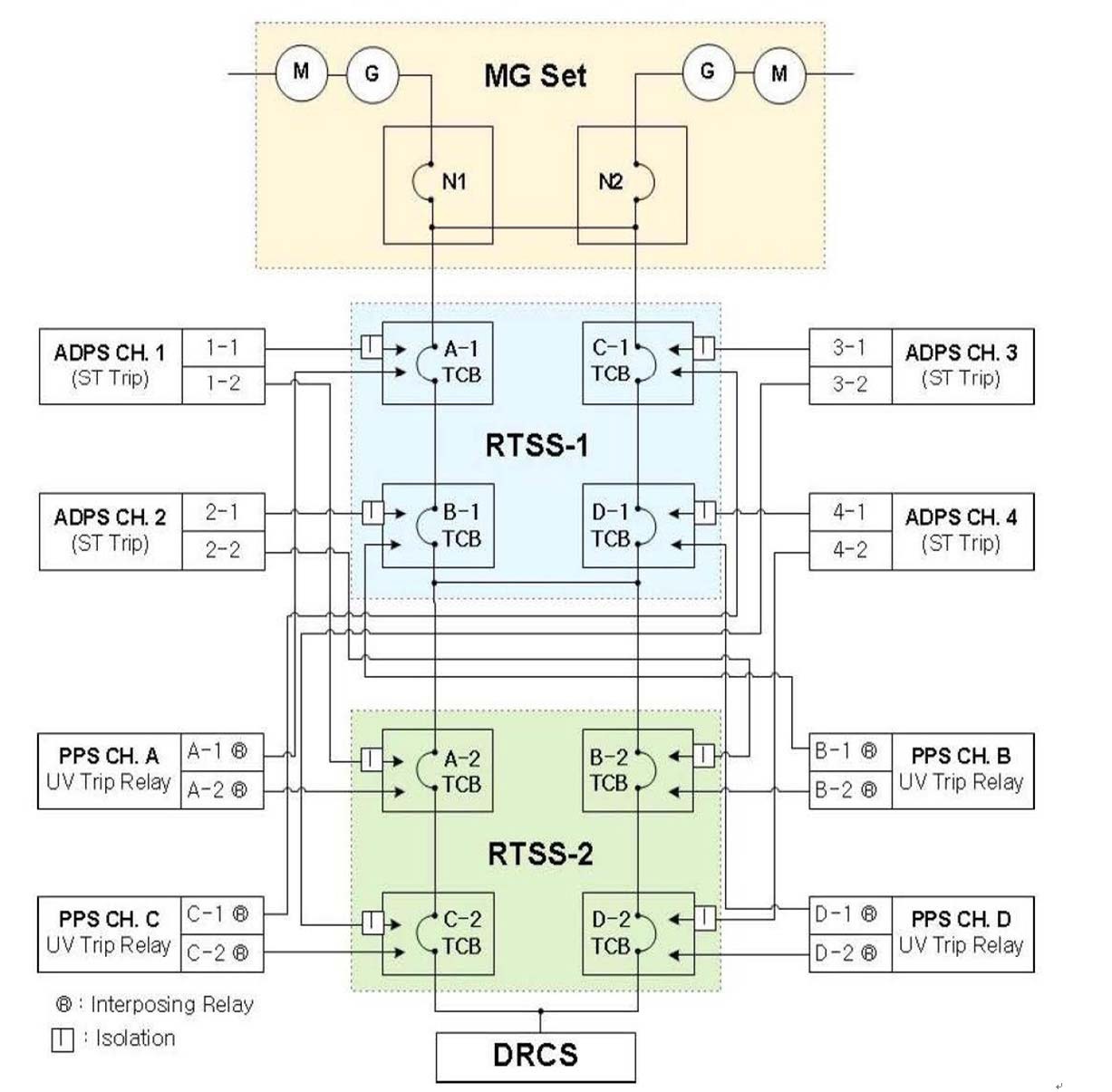
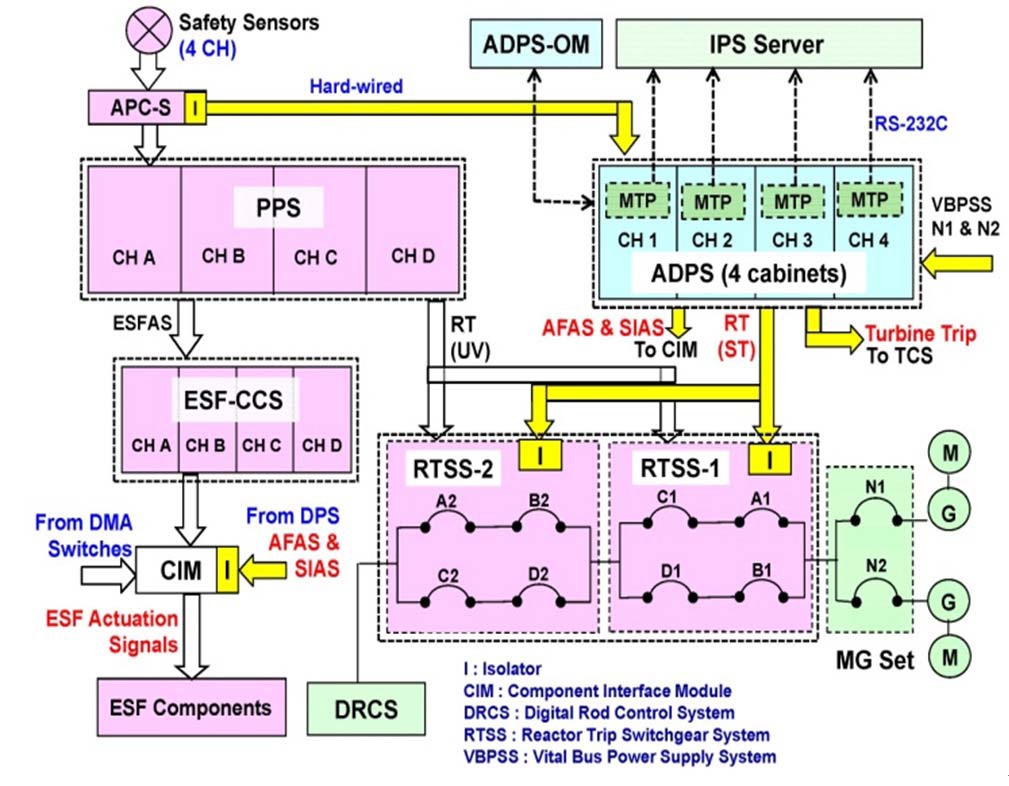
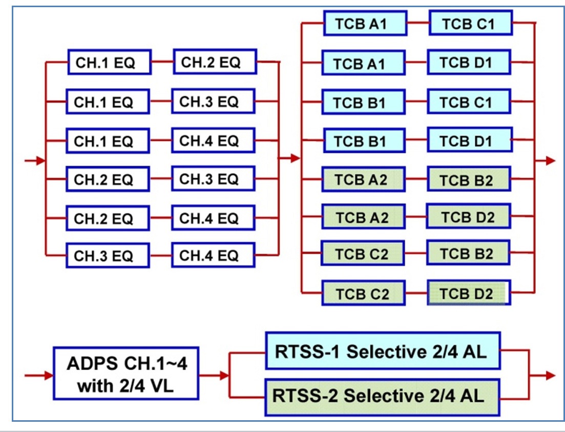
The ADPS has direct interfaces with the RTSS as depicted in Figures 2 and 5. Figure 7 illustrates the system block diagram for ADPS. The local coincidence logic (LCL) in each ADPS channel has the 2/4 voting logic. Each ADPS channel initiates the reactor trip or ESF (i.e., AFAS & SIAS) signals when the input signals from four sensors meet the 2/4 voting logic, which also accommodates the 2/3 and 2/2 voting logics. The 2/4 voting logic with four channels can be explained with six parallel connections of two serially-connected channels as shown in Figure 6. This means that at least two channels are required to be operational for the ADPS operability.
Figure 5 depicts the ADPS to the RTSS 1&2 interfaces. Each RTSS has four separate trip circuit breakers (TCBs). Each TCB can be tripped to open when either the Under-Voltage (UV) relay or the Shunt Trip (ST) relay is actuated.
For the diversity strategy between the PPS and the ADPS, the PPS provides its outputs to the total eight coils of UV relays, and the ADPS also provides its outputs to the total eight coils of ST relays. For the additional D3 concerns, equipment diversity between RTSS-1 and RTSS-2 will be provided.
The combination of two RTSS is necessary not only for the ADPS but also for the PPS interfaces, because one RTSS with four (4) TCBs has the limitations of availability caused by its selective 2/4 actuation logic.
In general, a 2/4 voting logic consists of six (6) combinations (i.e., 2C4 = 6). In Figure 5, each RTSS has four TCBs. The RTSS-1 actuation logics are comprised of four (4) combinations of TCB actuations (i.e., A-C, A-D, B-C, and B-D), and the RTSS-2 actuation logics are also comprised of four combinations of TCB actuations (i.e., A-B, A-D, B-C, and C-D). Therefore, the reactor trip actuations of one RTSS can’t be full 2/4 logics. The actuation logic with one RTSS is called a selective 2/4 actuation logic.
Trip actuation of either RTSS-1 or RTSS-2 can cause the final reactor trip. Therefore, the RBD of RTSS-1 and RTSS-2 should be connected in parallel as depicted in Figure 6. The combination of RTSS 1&2 leads to the total eight parallel RBD connections of two serially-connected TCBs as illustrated in Figure 6. Therefore, the combined effects of RTSS-1&2 correspond to a full 2/4 actuation logic. Compared with the selective 2/4 actuation logic with one RTSS, the full 2/4 actuation logics of RTSS-1&2 have the benefit to meet the single-failure criterion even during the RTSS test for each TCB.
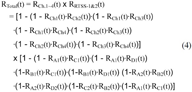
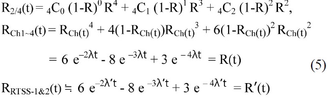
Using the RBD of Fig. 6, the ADPS reliability of the reactor trip can be expressed with either Eq. (4) or (5).
Where the following are assumed:
1) System components are operated in the constant failure rate region,
2) Failure rates of all ADPS channels are the same, and
3) Failure rates of all TCBs are the same.
If RCh1(t) = RCh2(t) = RCh3(t) = RCh4(t) = RCh(t), then RCh(t) = e -λCh·t = e -λ't.
If RA1(t) = RA2(t) = RB1(t) = RB2(t) = RC1(t) = RC2(t) = RD1(t) = RD2(t) = RTCB(t), then RTCB(t) = e -λTCB·t = e -λ't.
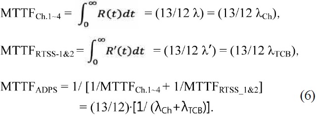
Total system reliability can also be expressed as:
By comparing Figures 4 and 6 to each other, the fault masking capability of the APDS can be clearly explained with Figure 6. There is no redundant signal path in Figure 4. However, Figure 6 indicates that a lot of redundant paths are provided in the RBD of the DPS-RTSS combination for the ADPS. Up to two faulted channels and/or TCBs can be masked.
3. ADPS DESIGN FEATURES FOR FAULT AVOIDANCE
Fault avoidance or fault prevention approaches are employed during the design and development phase to reduce the number of faults introduced during this phase of the system life cycle. The fault avoidance principles include the avoidance of unnecessary complexity in functional specification, the application of well defined development processes, the use of appropriate methods and tools, the use of competent and knowledgeable personnel, the application of suitable rules and guidelines, the use of dependable and well understood components and platforms, and taking into consideration lessons learned from past mistakes and faults in similar systems [8].
Fault avoidance efforts regarding the ADPS design should be done twofold as follows:
? A plant-wide CCF reduction approach is required to maintain the ADPS functions during the CCF of safety I&C systems, including the PPS and ESFCCS, based on the plant D3 requirements [9], and
? A system internal fault tolerance approach is required to enhance the reliability and availability of the ADPS.
Compared with the DPS for the APR1400 nuclear units, many fault avoidance design features are provided for the ADPS. The fault avoidance design features can be summarized as follows:
? System software design class has been upgraded from the combination of ITS & ITA for the DPS to ITS only for the ADPS. The ITA software is reviewed by the design team during software design processes, while the ITS software is verified by an independent V&V team. Therefore, the software design faults can be reduced through the V&V activities.
? System communication methods between the DPS and the IPS have been changed from a bidirectional network to a dedicated unidirectional data-link method. The unidirectional data-link can prevent any malicious changes of system data from others. Levels 4 and 3 equipment of the cyber security program are required to use a unidirectional data transfer method [16].
? Major system MMI has been changed from the IPS operator station to the ADPS Operator Modules (ADPS-OM).
? System platform is changed from the distributed control system (DCS) to the FPGA-based logic controller (FLC).
? ADPS cabinets are designed as a non-safety class, but
the PI sensors and the reactor trip actuation devices (i.e., RTSS) for the DPS input/output interfaces are changed from non-Class 1E to Class 1E.
? RTSS 1&2 will be implemented with at least two (2) diversity principles, which are the equipment diversity between RTSS-1 and RTSS-2, and the RTSS trip coil diversity between the undervoltage trip coils driven by the PPS, and the shunt trip coils driven by the ADPS.
? The location of the ADPS cabinets will be more distributed from two separate rooms to four separate rooms.
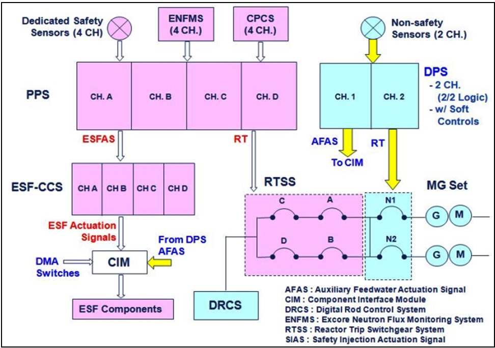
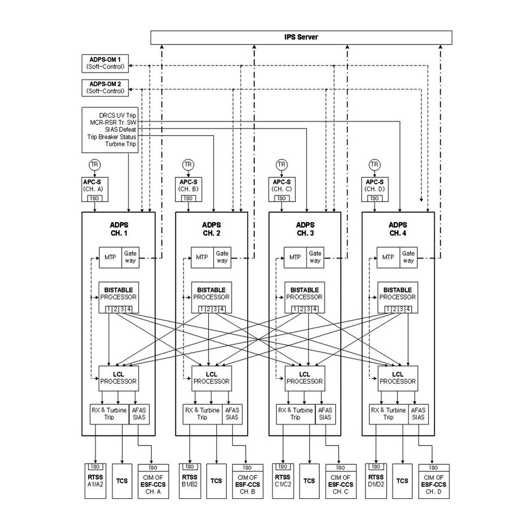
The ADPS shown in Figure 7 has the fault masking and avoidance design features described in this paper.
Dedicated diverse PI sensors are used for the DPS for OPR1000 and APR1400 nuclear units. However, the ADPS will use the class 1E PI sensors (rather than dedicated non-Class 1E PI sensors) through the isolators because of the following reasons:
? The environmental qualification level of the PI sensors should be enhanced considering the newly added SIAS function, which should be maintained during the harsh environment of an LBLOCA event,
? U.S. NRC’s 10 CFR 50.62 allows the use of nondedicated sensors for the ATWS mitigation system [4], and
? Diversity strategies for the DAS for advanced reactors are not uniform. Dedicated non-safety grade sensors are used for the two channel DAS for the APR1400 and AP1000 plants. However, safety-grade sensors are used, and they are shared by both the protection system and the four channel DAS, for the US-APWR and U.S. EPR plants [13&14].
4. ADPS FAULT DETECTION, LOCATION, CONTAINMENT, AND RECOVERY
Fault detection of the ADPS can be initiated by the trouble alarms. The trouble alarm is generated by the ADPS program logic if any trouble occurs. The troubles include the cabinet door being open, any trouble of power supplies, controller errors, etc. Each ADPS channel separately generates its own trouble alarm.
In addition, the maintenance and test panel (MTP) in each channel can reports the detailed cause of its trouble alarm. Watchdog timers will also be applied to the ADPS design to detect the occurrence of S/W CCF. A watchdog timer can detect faults in a few seconds when the faults halt the processor [10]. Most of the fault location process can be done with the help of ADPS trouble alarms on the ADPS-OM and the MTP trouble report.
Fault containment of the ADPS can be manually done by the bypass of the troubled channel. Fault recovery can also be done manually by the replacement or maintenance of troubled equipment, and then the removal of the channel bypass. Each channel controller has redundant dual CPU modules and dual power supply modules. These modules are hot-swappable. The fault detection, location, containment, and recovery processes for the ADPS will be further developed, and will be specified in detail in the system technical manual.
5. ADPS FAULT TOLERANCE EVALUATION
The major fault-tolerant capability of the ADPS comes from the H/W redundancy as described in Section II of this paper. The DPS for APR1400 has no channel redundancy, and it has no redundancy of final actuation devices. Therefore, all the major equipment is connected in series in the RBD of Fig. 4. Equation (3) shows that the mean time to failure (MTTF) of the APR1400 DPS is about a half of the single channel case. By contrast to the APR1400 DPS case, the RBD of Fig. 6 for the reactor trip of ADPS shows a lot of serial and parallel combinations of DPS channels and RTSS TCBs. As a result of the RBD analysis, the MTTF of the ADPS is about the same as the single channel case.
Channel reliability of the ADPS is expected to be higher than that of the APR1400, because the PI sensors will be changed to Class 1E rather than non-Class 1E, and all of the system S/W will be designed as ITS class. The reliability of reactor trip actuation devices for the ADPS is also expected to be higher than that for the DPS of APR1400, because the Class 1E TCB’s of RTSS will replace the non-Class 1E MG set breakers, i.e., the failure rate of the Class 1E TCB is expected to be lower than that of the non-Class 1E MG set breaker.
The MTTF Improvement Ratio (MIR) can be defined as Eq. (7) to compare the ADPS-MTTF (Eq. (6)) to the DPS-MTTF (Eq. (3)) for reactor trip function. The MIR evaluation result shows that the MTTF of the ADPS can be enhanced at least twice compared with that of the DPS for APR1400:
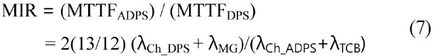
∴ MIR ≥ 2(13/12) ≒ 2.17
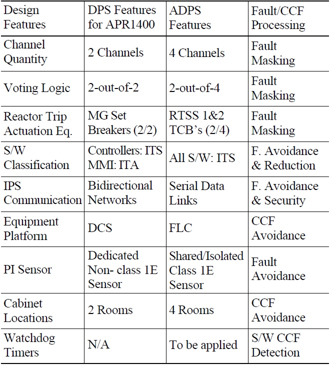
Besides the fault masking features, several fault avoidance and detection features will be incorporated in the ADPS design as illustrated in Table 1.
[Table 1.] Fault Tolerance Features of the ADPS

Fault Tolerance Features of the ADPS
Various fault-tolerant design features of the ADPS have been introduced to enhance the system reliability and the plant protection reliability against CCFs within the safety-grade protection systems. The most significant fault-tolerant feature of the ADPS reactor trip function is the fault masking capability with the use of four redundant channels with the 2/4 voting logic, and the use of multiple (total eight) TCBs of RTSS 1&2 for the 2/4 actuation logic. With this fault masking capability, the MTTF of the ADPS is expected to be doubled compared with that of the DPS for the APR1400.
In addition to the fault masking features, several fault avoidance and detection features have been developed for the ADPS design as described in Table 1. Fault diagnosis functions to help the fault detection, location, containment, and recovery processes will be further developed for the ADPS.
Therefore, it is expected that the new DPS in Korean nuclear units will be even more reliable and dependable based on the ADPS design techniques. The ADPS will be further developed by KEPCO E&C to enhance its fault tolerance capability and to meet the plant D3 requirements.
ADPS Advanced Diverse Protection System
AFAS Auxiliary Feedwater Actuation Signal
AL Actuation Logic
APC-S Auxiliary Process Cabinet - Safety
APR Advanced Power Reactor
ATWS Anticipated Transient without Scram
CCF Common Cause Failure
CCS Component Control System
CH. Channel
D3 Diversity and Defense-in-Depth
DAS Diverse Actuation System
DBE Design Basis Event
DPS Diverse Protection System
DRCS Digital Rod Control System
EQ Equipment
ESF Engineered Safety Feature
FLC FPGA-based Logic Controller
FPGA Field-Programmable Gate Array
I&C Instrumentation and Control
IPS Information Processing System
ITA Important-to-Availability
ITS Important-to-Safety
LBLOCA Large-Break Loss of Coolant Accident
MG Set Motor Generator Set
MIR MTTF Improvement Ratio
MMI Man-Machine Interface
MTP Maintenance and Test Panel
MTTF Mean Time to Failure
OM Operator Module
OPR1000 Optimized Power Reactor 1000
PI Process Instrumentation
PPS Plant Protection System
PZR Pressurizer
RBD Reliability Block Diagram
RTSS Reactor Trip Switchgear System
SIAS Safety Injection Actuation Signal
ST Shunt Trip
TCB Trip Circuit Breaker
UV Under-Voltage
VL Voting Logic
Further, a DMT upper bound based on an AF relay can be found as follows:
Theorem 2.
d*(r) = 1 - r.