Global navigation satellite systems (GNSSs), including global positioning system (GPS), GLObal NAvigation Satellite System (GLONASS), Galileo, and Compass, will be fully deployed and operational in a few years [1]. An antenna for a GNSS receiver requires broadband characteristics, such as impedance matching and 3-dB axial ratio (AR) bandwidths, right-hand circularly polarized (RHCP) radiation, a wide CP radiation beamwidth (> 100°) facing the sky, and a high front-to-back ratio. The use of a variety of single- and dual-band CP antennas in the GNSS frequency bands has been reported: e.g., crossed dipole [2-6], microstrip patch [7-10], slotted [11-13], near-field resonant parasitic [14,15], and stacked patch [16,17] antennas. However, most of these antennas have insufficient 3-dB AR beamwidth to meet the requirements of GNSS applications, owing to the lack of techniques to broaden the CP radiation beamwidth. Recently, several techniques have been introduced to broaden the CP radiation beamwidth of microstrip patch antenna. These have included a pyramidal ground structure with a partially enclosed flat conducting wall [18], auxiliary radiator [19], applying higher order modes [20], loading gaps and stubs on the patch [21], and microstrip-monopole combination [22]. Most of these techniques are effective only for single-band antennas. The technique for extending the substrate beyond the ground plane was introduced for dual-frequency patch antennas to realize a wide CP radiation beamwidth [23], but its 3-dB AR bandwidths are relatively narrow.
This paper introduces composite cavity-backed crossed scythe-shaped dipoles as a simple method to broaden the CP radiation beamwidth for single- and dual-band operations. A vacant-quarter printed ring acts as a 90° phase delay line of the primary radiating element to generate the CP radiation [24]. The crossed scythe-shaped dipole [25] is first characterized in free space and is then incorporated with a cavity-backed reflector. Additional resonances are generated by dividing the dipole arm into two branches with different lengths. Both the single- and dual-band antennas yielded excellent performance in terms of broad bandwidth, wide beamwidth radiation, and high radiation efficiency. Compared to the composite cavity-backed arrowhead- shaped dipoles [26-28], the presented antennas have a wider impedance matching bandwidth, a wider 3-dB AR bandwidth, and a wider CP radiation beamwidth.
Ⅱ. DESIGN OF CROSSED SCYTHE-SHAPED DIPOLE IN FREE SPACE
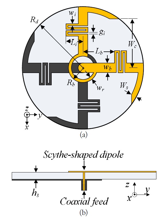
Fig. 1 shows the geometry of the crossed dipole without the reflector. Each dipole arm contains a meander line, with the end shaped like a scythe. The scythe-shaped dipoles working at 1.58 GHz were first designed in free space and then crossed through a vacant-quarter printed ring to achieve CP radiation. The antenna was printed on a circular RT/Duroid 5880 substrate with a radius of 25 mm, a relative permittivity of 2.2, a loss tangent of 0.0009, and a thickness of 0.508 mm (20 mils). The antenna was fed with a 50 Ω coaxial line. The outer conductor of the coaxial line was connected to the dipole arms on the bottom side of the substrate. The inner conductor of the coaxial line was extended through the substrate and connected to the dipole arms on the top side. The antenna was optimized via ANSYS high-frequency structure simulator (HFSS) software to have a broad impedance matching bandwidth and a CP center frequency at 1.58 GHz, where the CP center frequency was defined as the frequency at which the minimum AR occurs. The optimized antenna design parameters were:
Ⅲ. COMPOSITE CAVITY-BACKED CROSSED SCYTHE-SHAPED DIPOLE
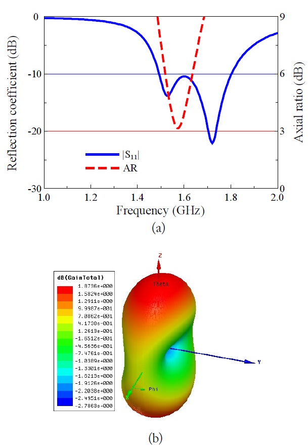
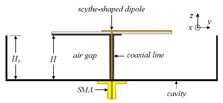
A unidirectional radiation pattern was achieved and the CP radiation was improved by incorporating a cavitybacked reflector into the crossed scythe-shaped dipoles. A side view of the geometry of the antenna is given in Fig. 3. The reflector is a rectangular box with base dimensions of 120 mm×120 mm and a height of
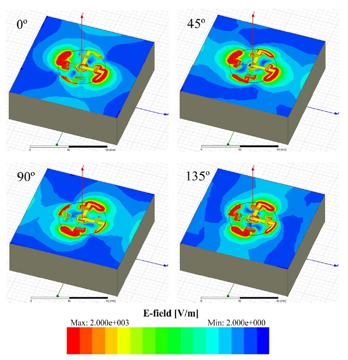
Research has shown that the radiation of a cavity-backed antenna is determined more directly by the electric field distribution in the aperture than by the radiator current [4]. Accordingly, the electric field distribution in the aperture at 1.58 GHz was examined and is illustrated in Fig. 4 for phase angles of 0°, 45°, 90°, and 135°, in order to understand the CP behavior of the proposed cavity-backed antenna. A right-hand rotated electric field is apparently concentrated within the cavity aperture, and a strong electric field is present near the scythe-shaped dipole arms. This indicates that the radiation of the composite cavitybacked crossed scythe-shaped dipole antenna is RHCP.
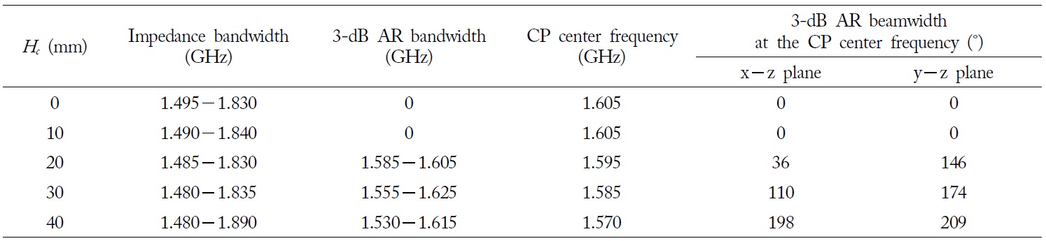
The characteristics of the antenna at different heights (

Performance characteristics of the crossed scythe-shaped dipole antenna for different cavity heights
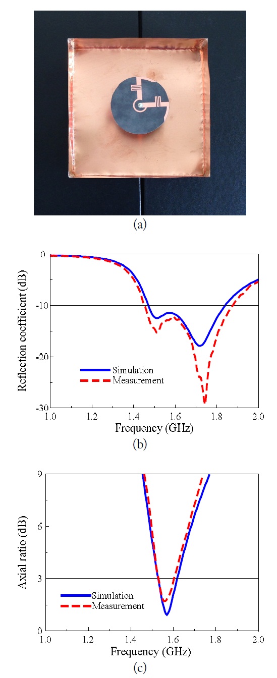
The proposed composite cavity-backed crossed scytheshaped dipole antenna was fabricated and measured. The primary radiating elements were built on both sides of the RT/Duroid 5880 substrate with a copper thickness of 17 μm. The cavity-backed reflector was constructed from 5 copper plates (one 120 mm× 120 mm and four 120 mm × 40 mm) with a thickness of 0.2 mm. An Agilent N52- 30A network analyzer and a 3.5-mm coaxial calibration standard GCS35M were used for the reflection coefficient measurement of the prototype in Fig. 5(a). The measured and simulated reflection coefficients for the proposed antenna are compared in Fig. 5(b). The measured bandwidth for the ?10 dB reflection coefficient was 1.462? 1.858 GHz. These values agreed rather closely with the simulated bandwidth of 1.475? 1.835 GHz. The radiation patterns were measured in a full anechoic chamber with dimensions of 15.2 m (
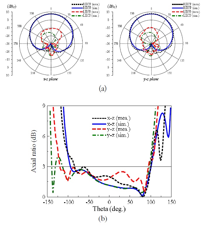
Fig. 6(a) shows the 1.58 GHz radiation patterns of the antenna with RHCP, the symmetrical profile, and the wide beamwidth in both the x?z and y?z planes. The measurements resulted in a gain of 7.53 dBic, a front-to-back ratio of 23.7 dB, and half-power beamwidths of 107° and 108° in the x?z and y?z planes, respectively. Fig. 6(b) shows the simulated and measured AR values of the antenna versus the theta angle at 1.58 GHz, with a very wide CP radiation beamwidth. The measured beamwidths for AR < 3 dB were 182° and 212° in the x?z and y?z planes, respectively. Additionally, the measurements showed a high radiation efficiency of 95.4%, which closely agrees with the simulated value of 97.5% at 1.58 GHz.
Ⅳ. COMPOSITE CAVITY-BACKED CROSSED TWO-BRANCH SCYTHE-SHAPED DIPOLE
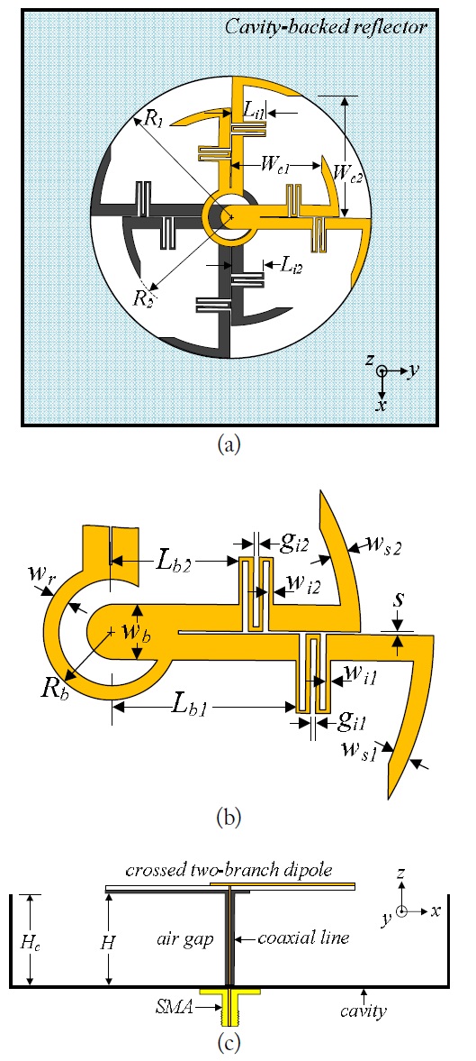
An additional resonance at 1.28 GHz was produced by adding a longer branch to the arm of the scythe-shaped dipole, as shown in Fig. 7. A rectangular cavity with basic dimensions of 120 mm × 120 mm and a height of
[Table 2.] Performance characteristics of the dual-band antenna for different cavity heights
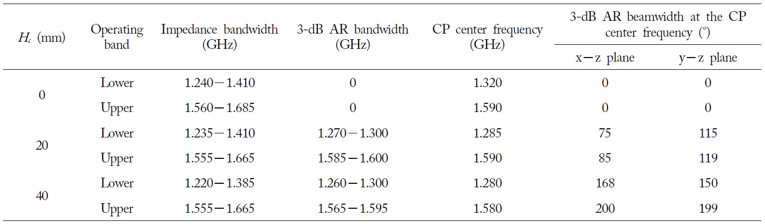
Performance characteristics of the dual-band antenna for different cavity heights
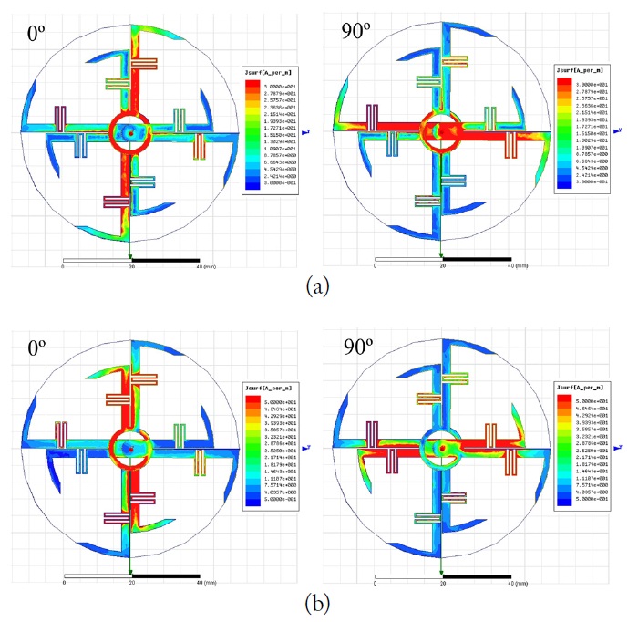
Each branch of the two-branch scythe-shaped dipole arm was confirmed to work separately on each desired bands by calculating the current distribution on the radiator of the dual-band antenna at 1.28 and 1.58 GHz. These results are presented in Fig. 8 with the phase angles, 0° and 90°. The large and small branches worked for the lower and higher bands, respectively. Additionally, for both frequencies, the x-axis oriented dipole arms worked at the phase angle of 0°, and the y-axis oriented dipole arms worked at the phase angle of 90°. These results indicate the good CP behavior of the proposed dual-band antenna.
As shown in Table 2, which shows the performance characteristics of the crossed two-branch scythe-shaped dipole for different cavity heights (
The HFSS simulations showed that the antenna yielded AR > 3 dB in both bands with the planar reflector (the antenna with
The proposed dual-band antenna with
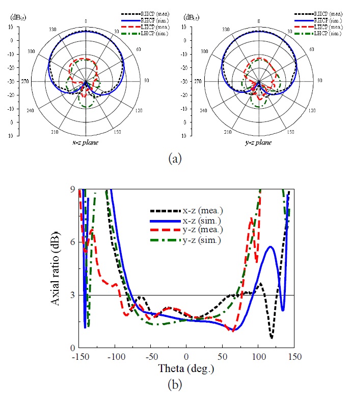
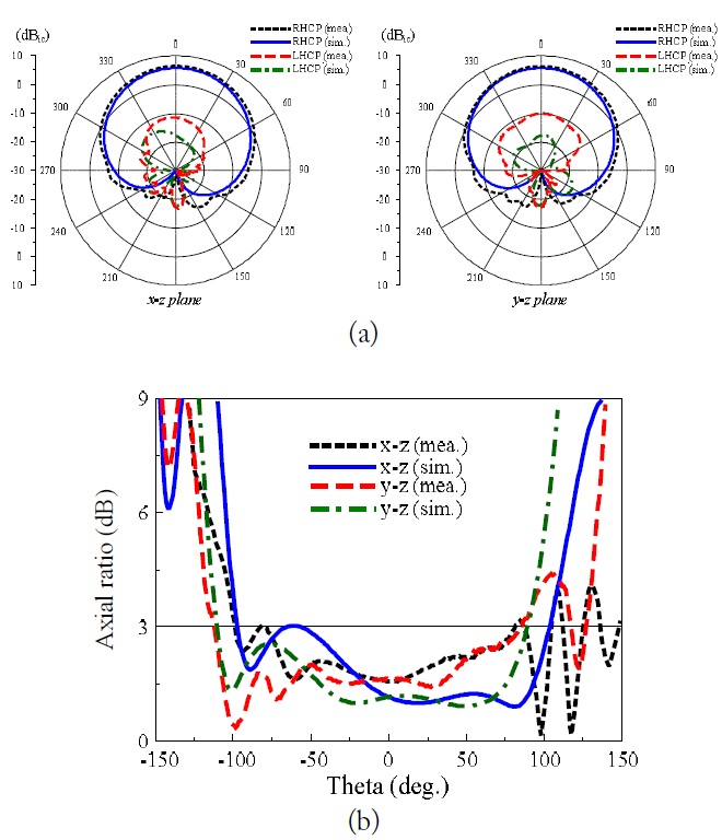
Figs. 10 and 11 show the radiation patterns and AR values as functions of the theta angle for the dual-band antenna at 1.28 and 1.58 GHz, respectively. The measurements agreed well with the HFSS simulation results and showed RHCP radiation, a wide CP radiation beamwidth, and a symmetric pattern in both the x?z and y?z planes. At 1.28 GHz, the measurements resulted in a gain of 6 dBic, a front-to-back ratio of 24 dB, and a 3-dB AR beamwidth of 168° and 150° in the x z and y z planes, respectively. At 1.58 GHz, the measurements resulted in a gain of 5.9 dBic, a front-to-back ratio of 24 dB, and a 3- dB AR beamwidth of 200° and 199° in the x?z and y?z planes, respectively. Additionally, the measured radiation efficiencies were 90.4% and 87.6%, and the simulated values were 95.4% and 89.4%, at 1.28 GHz and 1.58 GHz, respectively.
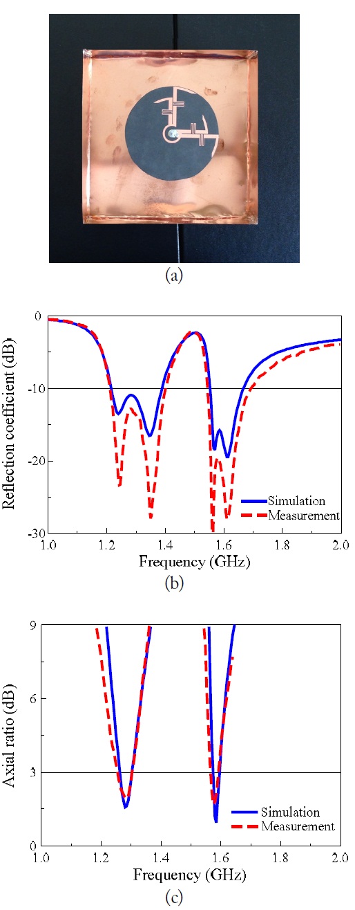
The proposed dual-band antenna with Hc = 40 mm was also fabricated and measured. Fig. 9(b) compares the simulated and measured reflection coefficients of the prototype shown in Fig. 9(a). The measured impedance bandwidths for the 10 dB reflection coefficient were 1.218? 1.400 GHz and 1.547? 1.700 GHz, values that agree rather closely with the simulated bandwidths of 1.220? 1.385 GHz and 1.555? 1.665 GHz. Fig. 9(c) compares the simulated and measured AR values of the dual-band antenna; good agreement between the two can be observed. The measured 3-dB AR bandwidths were 1.255 1.300 GHz and 1.560? 1.590 GHz, and the simulated 3-dB AR bandwidths were 1.260? 1.300 GHz and 1.565? 1.595 GHz. In addition, the measurement yielded CP center frequencies for the lower and upper bands of 1.28 and 1.575 GHz, with an AR of 1.7 and 1.86 dB, respectively. The impedance matching and 3-dB AR bandwidths of the proposed dual-band antenna completely cover the GPS L1, GLONASS L1, Compass B1, Galileo E1 and E6 bands.
Figs. 10 and 11 show the radiation patterns and AR values as functions of the theta angle for the dual-band antenna at 1.28 and 1.58 GHz, respectively. The measurements agreed well with the HFSS simulation results and showed RHCP radiation, a wide CP radiation beamwidth, and a symmetric pattern in both the x? z and y? z planes. At 1.28 GHz, the measurements resulted in a gain of 6 dBic, a front-to-back ratio of 24 dB, and a 3-dB AR beamwidth of 168° and 150° in the x? z and y? z planes, respectively. At 1.58 GHz, the measurements resulted in a gain of 5.9 dBic, a front-to-back ratio of 24 dB, and a 3- dB AR beamwidth of 200° and 199° in the x? z and y? z planes, respectively. Additionally, the measured radiation efficiencies were 90.4% and 87.6%, and the simulated values were 95.4% and 89.4%, at 1.28 GHz and 1.58 GHz, respectively.
Wide beamwidth CP composite cavity-backed crossed scythe-shaped dipoles were introduced for single- and dualband operations. The scythe-shape dipoles with meander lines resulted in a reduction of the radiator sizes. The achieve CP radiation was achieve using a vacant-quarter printed ring with broadband impedance matching characteristics as the 90° phase delay line. The CP radiation was improved by the use of the composite scythe-shaped dipoles and a cavity-backed reflector. The proposed single-band antenna yielded bandwidths of 1.462? 1.858 GHz for a 10 dB reflection coefficient and 1.530? 1.595 GHz for a 3-dB AR, in addition to a very wide CP radiation beamwidth (> 190°). The proposed dual-band antenna yielded bandwidths of 1.218? 1.400 GHz and 1.547? 1.700 GHz for the 10 dB reflection coefficient and 1.255? 1.300 GHz and 1.560? 1.590 GHz for a 3-dB AR, in addition to a wide CP radiation beamwidth (> 160°) in both bands.