Radio frequency identification (RFID) now finds applications in many areas, including logistics tracing, traffic control, environmental surveillance, and medical and grocery tracking. The RFID system consists of a reader and a tag, and the UHF RFID system operates at the bands of North America (902 928MHz), Europe (865 867MHz), Japan (916.7 923.5MHz), and Korea (917 923.5MHz). RFID is classified into passive and active types according to the method used to obtain the energy source of the electric wave. The passive type obtains the transmission energy from the electric wave received from the reader. The active type obtains the transmission energy from the battery. The passive tag has a semi-permanent life, no battery, is inexpensive, and is suitable for short range communication. On the other hand, the active tag can be used for long range communication because the battery is built into the tag.
However, the high price and the battery lifetime currently restrict the use of RFID. Several papers have been published on RFID antennas for both passive and active tags [1-13], such as a shorted micro-strip patch antenna that uses an inductively coupled feed for the UHF RFID tag [2], miniaturization of a rectangular loop antenna using a meander line for RFID tags [3], RFID tag antennas that use an inductively coupling feed [4], a flexible planar RFID tag antenna with low performance degradation from nearby target objects [8], a broadband UHF RFID tag antenna with a rectangular- loop feed and additional patches [9], a planar loop tag antenna with bandwidth enhancement for the UHF RFID system [10], a long range UHF RFID tag with a rectangular metallic cavity structure [11], and a design for an integrated loop coupler and loop antenna for RFID applications [12]. The active RFID can provide long range data transmission because it uses different fields (the environmental monitoring, military, and health care). The requirement for food history management systems is growing due to the increasing importance of food safety problems. The freshness of vegetable, meat, or dairy product is very important. An active RFID tag is attached to the product (a vegetable, meat, and dairy product) that requires refrigeration and the temperature/process of distribution is monitored so that product spoilage can be prevented.
In this paper, we present a design for a semi-active sensor tag antenna for RFID food systems. The proposed tag antenna is composed of a radiation patch, sensor tag chip, temperature sensor, oscillator, and battery. The proposed tag antenna covers the range of 916.7-923.5MHz (Korean and Japanese standards). We have conjugated matching between the tag antenna and the sensor tag by using a U-shaped stub. The selection of the geometry of the U-shaped stub allows the tag antenna to be tuned to the operating frequency. The simulation and fine tuning of the tag antenna were carried out using commercial high frequency structure simulator (HFSS) software.
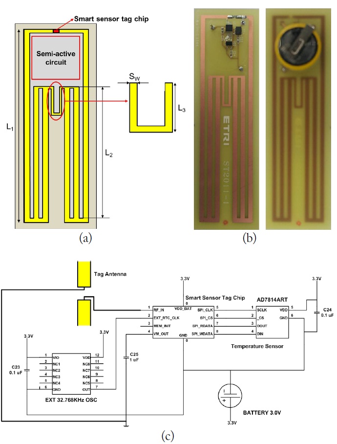
Fig. 1 shows the geometry of the proposed semi-active sensensor tag antenna for an RFID food system.
The tag antenna is supported by a dielectric substrate of a height equal to 0.8 mm and a relative dielectric constant of 4.3 (FR-4, loss tangent =0.025). The semi- active circuit is composed of a sensor tag chip (ETRI tag chip), temperature sensor (AD7814ART), oscillator (EXT 32.768 kHz OSC), and battery (CR2023). The oscillator sends a time clock signal to the sensor tag and the temperature sensor measures the temperature attached to the product (a vegetable, meat, or dairy product) according to the setup time. The tag antenna transmits the measured temperature. The tag antenna has dimension of 30 mm × 100 mm, and the optimal design parameters can be chosen as
Ⅲ. MEASURED AND SIMULATED RESULTS
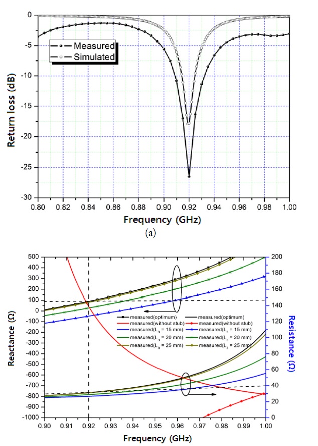
Fig. 2 shows the simulated and measured results of the proposed tag antenna. The simulation results were obtained from commercial software on an Ansys HFSS, and the reliability of the obtained results was confirmed.
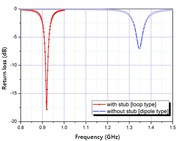
Fig. 2(a) shows the results of a tag antenna with a sensor tag chip, temperature sensor, oscillator, and battery, operating at a frequency of 920MHz. The measured bandwidth for return loss < 10 dB is 20MHz (910-930MHz), which covers the 6.8MHz bandwidth requirements of the Korean and Japanese standards for the UHF RFID band (916.7 923.5MHz). The measured bandwidth for return loss < 5 dB is 50MHz (900-950MHz), which covers the 26MHz bandwidth requirements of the North America band (902- 928MHz). The impedance responses of the tag antenna and of the ETRI chip are shown in Fig. 2(b). As
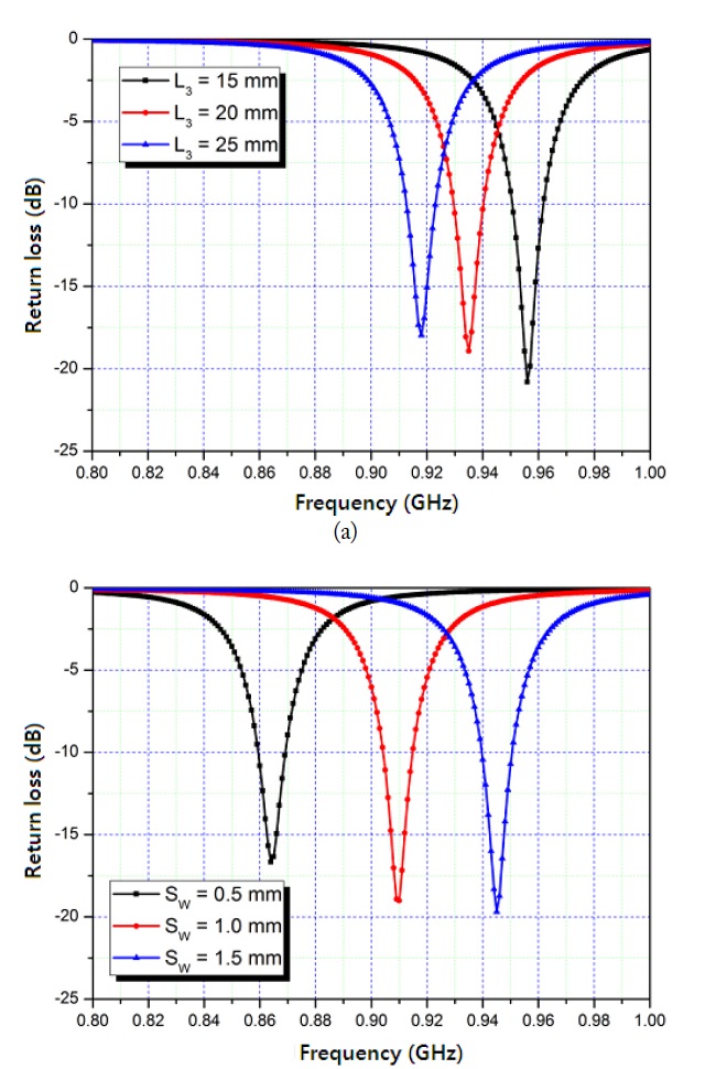
We simulated the design variable for the proposed tag antenna structure. Fig. 3(a) shows that as the length
The simulated return loss of the designed antenna with and without the U-shaped stub is shown in Fig. 4. With the U-shaped stub, the antenna is a loop type. Without the Ushaped stub, antenna is dipole type. As shown in the figure, when the U-shaped stub is present, the proposed tag antenna satisfies the operating frequency. This confirms that the U-shaped stub is an important element in the tag antenna and chip with conjugate matching.
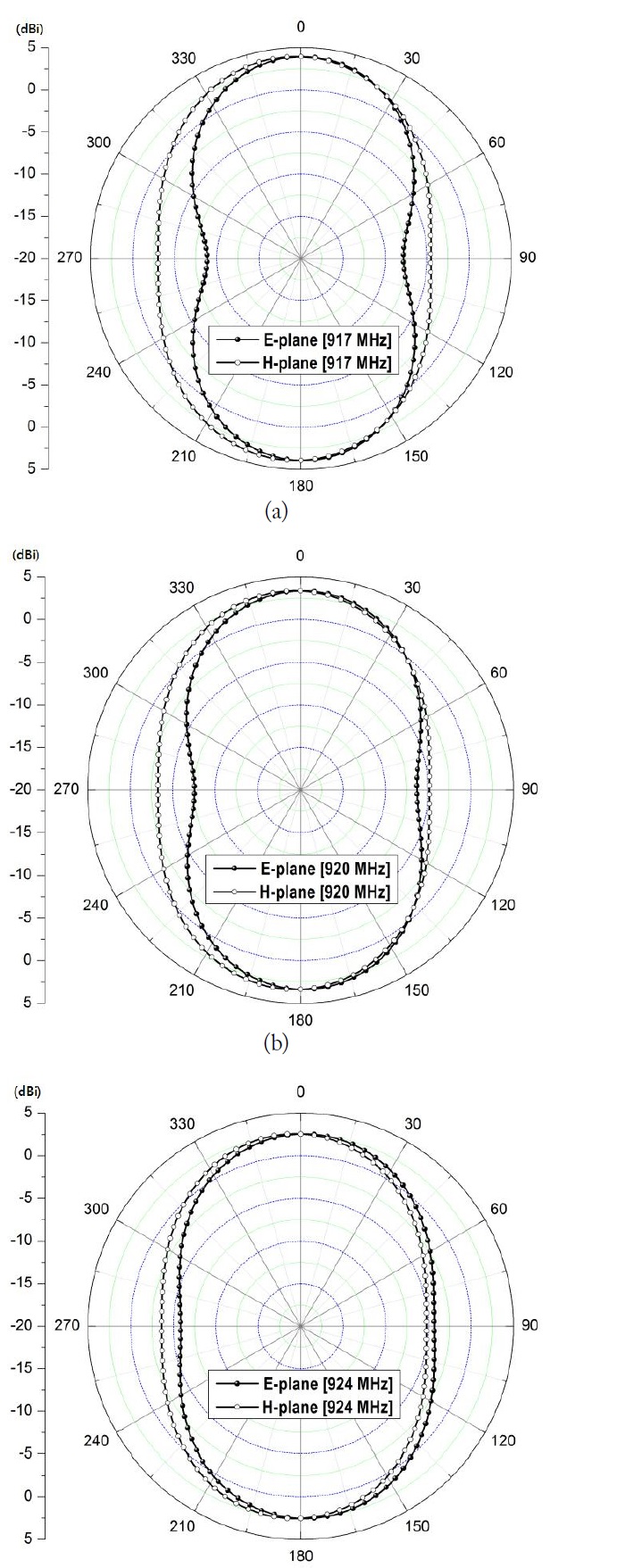
Fig. 5 shows the radiation patterns of the proposed tag antenna, measured in an anechoic chamber at the Korea RFID/ USN Center, Incheon, Korea. The radiation patterns in the E-plane are very dipole-like, while those in the H-plane are nearly omni-directional for all frequencies. In addition, the radiation patterns are stable across the respective operating frequency bands. The realized gain values for these three cases at 917, 920, and 924MHz are 3.35, 3.35, and 2.53 dBi, respectively.
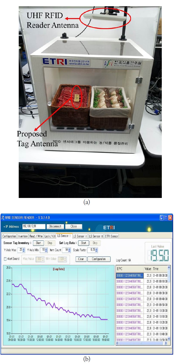
Fig. 6(a) shows the setup environment for groceries temperature monitoring. As shown in figure, the groceries, a reader antenna, and a semi-active tag antenna are positioned inside the shielding box. In this experiment, the groceries used were meat and a semi-active tag antenna was adhered to the top for the meat. The separation distance between the reader antenna and the semi-active tag antenna was 50 cm, and it measured the temperature of the meat at an interval of 10 minutes. Fig. 6(b) shows that this time interval after setup essentially provided temperature measurements on a real-time basis. Thus, the proposed tag antenna will be valuable for providing a real-time location for groceries and maintaining their freshness.
We compared the proposed tag antenna with existing temperature monitoring tag antennas. Table 1 shows that even though the proposed system is a semi-active structure, it has a very long read range.
[Table 1.] Comparison with other tag antennas
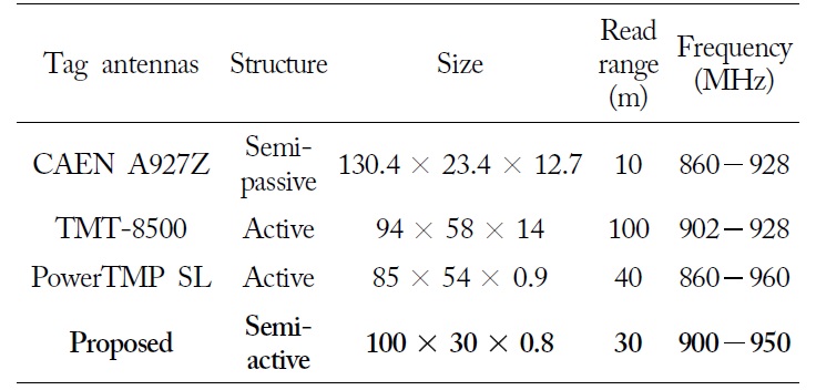
Comparison with other tag antennas
Designing a semi-active sensor tag antenna for RFID food system is challenging. The proposed tag antenna has been designed, fabricated, and characterized for UHF RFID communication applications. It is composed of a radiation patch, sensor tag chip, temperature sensor, oscillator, and battery. We conjugated matching between the tag antenna and the sensor tag by using a U-shaped stub. A semi-active tag antenna was adhered to the top of meat and this allowed real-time measurement of the meat temperature. This tag antenna will be useful in systems for real-time grocery location and for maintaining freshness.