The CANDU 6 Pressurized Heavy Water reactor core consists of 380 horizontal fuel channels submerged in a large volume (~215,000 L) of subcooled heavy water moderator in a cylindrical calandria vessel [1]. The heavy-water moderator also provides a secondary heat sink function. The calandria vessel is surrounded by a calandria vault with a large volume (~514,000 L) of light water. Each fuel channel consists of a Zr-2.5wt%Nb pressure tube concentrically located within a Zircaloy-2 calandria tube. Within each pressure tube there are twelve 0.5-m long fuel bundles, each consisting of Zr-4 clad fuel elements containing UO2 pellets. The fission and decay thermal energy produced in the UO2 fuel pellets is removed by heavy water coolant - the primary heat-transport fluid - circulating at about 10 MPa and 300℃ under normal operating conditions (NOC). The coolant flow is forced through the pressure tubes by the primary heat transport system (PHTS) pumps via the inlet and outlet feeder pipes connecting the respective inlet and outlet headers. At NOC, the total heat generation in the fuel, coolant and pressure tubes is 2061 MW, with an additional 95 MW (neutron moderation plus gamma heat) generated in the moderator and other core components (e.g., calandria tubes, guide tubes, tube sheets). The total core fission and decay heat, at NOC, is 2156 MW.
There are two independent control systems and two independent shutdown systems to shut the reactor in any design basis or severe-accident emergencies. For accidents with the reactor coolant pressure boundary intact, the decay heat is removed by the steam generator heat sink or a dedicated decay heat removal system. For loss-of-coolant accidents, the decay heat is removed by the Emergency Core Cooling System. For beyond design basis accidents the plants have adequate heat sink provisions to mitigate the accidents. These systems operate independent of external sources of electricity or other resources. In the Enhanced CANDU reactor, a severe accident recovery and heat removal system (SARHRS) has been incorporated to provide water makeup to:
Steam generators to prolong the secondary-side heat sink;
The calandria vessel and/or the calandria vault;
The containment spray to suppress containment pressure; and
Refill the reserve water tank (RWT) for severe accident management needs.
Even in the unlikely failure of the decay heat removal systems, the moderator system will prevent gross damage to the fuel and maintain fuel channel integrity. In the unlikely event that the moderator cooling also fails, the fuel channels would sag, disassemble and collapse as the moderator boils off; however, the core debris would still be contained within the calandria vessel as long as the vessel remains cooled on the outside by the calandria vault water. Only if sufficient calandria vault water boils off would the calandria vessel fail; this would take a long time, typically around 40 hours. This long delay in the failure of the calandria vessel provides time to implement Severe Accident Management procedures to arrest the progression of the accident.
For a pressurized heavy water reactor, accidents that result in damage to the reactor core fall into two classes: those for which the core geometry is generally preserved (limited core damage accidents) and those for which the core geometry is lost (severe core damage accidents). The latter are severe accidents, whereas limited core damage accidents are typically considered as part of the design basis. As such, there are provisions for the prevention and mitigation of limited core damage accidents before severe accident management is required.
An ultimate heat sink is an environment capable of absorbing heat from a nuclear power plant without an appreciable change in the heat sink temperature. Typically CANDU reactors use lake or sea water as the ultimate heat sink. Thus an unlimited supply of water is available to cool vital systems and the primary containment during any accident.
The objective of this paper is to provide an overview of heat sinks available in a CANDU reactor. A station blackout case was analysed using the MAAP4-CANDU code to gain insight into the maximum heat load during the event and the effect on the heat sinks.
2. ANALYSIS OF A STATION BLACKOUT IN A CANDU POWER PLANT
The assessment of backup and ultimate heat sinks was performed for a station blackout scenario, a transient initiated by losing off-site AC (Class IV) power with a subsequent loss of all on-site standby (Class III) and emergency electric power supplies. The analysis assumptions are provided in Table 1; none of the active heat sinks were used in the simulation. The decay heat removal was by passive heat sinks: the water inventories of the PHTS, moderator, steam generator secondary side, end shields and calandria vault. The analysis examined the efficacy of the passive heat sinks in a CANDU 6 reactor to remove the decay heat, and provided an understanding of the necessity of securing long-term heat sinks against prolonged station blackout.
The analysis presented in this paper uses generic CANDU 6 input parameters. The station blackout sequence and its progression are heavily dependent on the specific station conditions and may vary from the generic input used in this analysis. Therefore, the inferences made from this analysis are mainly indicative of the behaviour based on the input and boundary conditions applied.
Version v4.0.5A+ of the MAAP4-CANDU code was executed on a PC Pentium IV 1700 MHz computer. MAAP (Modular Accident Analysis Program) is an integral nuclear plant analysis code for modelling severe core damage accidents [2]. The MAAP code was developed for pressurized and boiling light water reactors by Fauske and Associates Incorporated, and is owned by the Electric Power Research Institute. The MAAP4-CANDU Channels System, developed by Ontario Power Generation, is the portion of MAAP4-CANDU that models the thermalhydraulic, thermal-chemical, and thermal-mechanical behaviour of the CANDU horizontal channels as they heat up and disassemble into debris. The CANDU core is different from that of PWRs and BWRs. The disassembly of the horizontal channels and core relocation during a severe accident is more complex. Several phenomenological models [3], [4] and [5] specific to the CANDU core have been implemented by best-estimate calculations. The MAAP4-CANDU Channels System is computationally intensive. A modular code structure was used to decouple the MAAP4-CANDU Channels System from other MAAP4- CANDU components and from MAAP4 generic routines, to allow better code maintainability, model improvements, and adjustments to other CANDU reactor configurations. Code improvements are thus performed in a more secure and independent manner.
The MAAP4-CANDU Channels System models characteristic (or representative) fuel channels and their contents after the channels are dry (i.e., empty of water) and during the channel heat up and subsequent processes (e.g., Zrsteam reaction, channel disassembly, suspended debris behaviour). Each characteristic channel represents a larger number of associated channels with similar power, elevations within the core, and feeder geometries. The core heat-up processes are modelled in a given characteristic channel only after the channel is deemed dry (i.e., when the water remaining in the channel, attached feeders and end fittings is less than a user input value, typically 1 kg). The Channels System also models the disassembly of the fuel and fuel channel into suspended debris. The processes after the debris (solid and molten) has moved to the terminal debris bed (i.e., the bottom of the calandria vessel) are modelled by a different portion of the MAAP4-CANDU code. Further details of the code and nodalization schemes are provided in [6] and [7].
The MAAP4-CANDU code uses three files containing input data: the parameter file, the input file and the channel data file. The parameter file for the generic CANDU 6 station consists of ~5,000 parameters, providing information
[Table 1.] Summary of SBO Simulation Assumptions for the MAAP4 CANDU
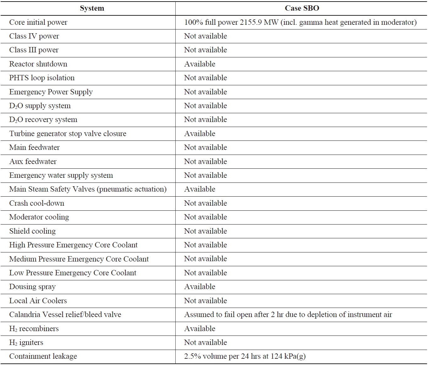
Summary of SBO Simulation Assumptions for the MAAP4 CANDU
on component geometries, model control and initial reactor parameters: pressures, temperatures, equipment volumes, water inventories, etc. The input file contains characteristics of the accident sequence to be analysed, such as a station blackout. The channel data file contains fuel and fuel channel temperatures and Zr oxide thicknesses, used as initial conditions when a channel becomes dry on the inside and the fuel and fuel channel heat transfer calculations begin.
The integrated response of the entire reactor and containment during the initiating stages of an accident and the subsequent severe accident events (e.g., core disassembly, calandria vessel failure) is simulated by the code. In this analysis the station blackout sequence was run to 500,000 s (~139 h or 5.8 days). The code execution time was ~30 min. Table 2 lists the sequence of significant events simulated during this code run.
2.2 Station Blackout Event Sequence
The accident sequence begins with the initiating event (time = 0 s); the loss of Class IV and Class III power causes the loss of motive power to pumps in the PHTS, moderator cooling, end shield and calandria vault cooling, steam generator feedwater, and recirculating cooling water systems. The accident progresses to severe core damage and core disassembly, because of the loss of the PHTS inventory, long-term emergency core cooling, moderator cooling, and shield and calandria vault cooling.
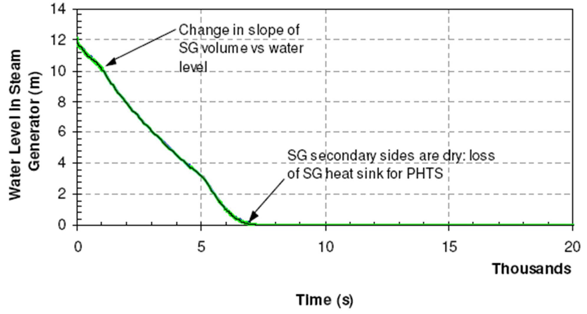
With the loss of Class IV and III power the reactor trips immediately (shut off rods are held out of core by electromagnets), and the pumps run down, ending the active heat sink capability. The steam generator secondary side water boils off (Fig. 1) and vents to the atmosphere, removing core decay heat for approximately 1.9 h and
[Table 2.] Sequence of Significant Events for a CANDU 6 Station Blackout
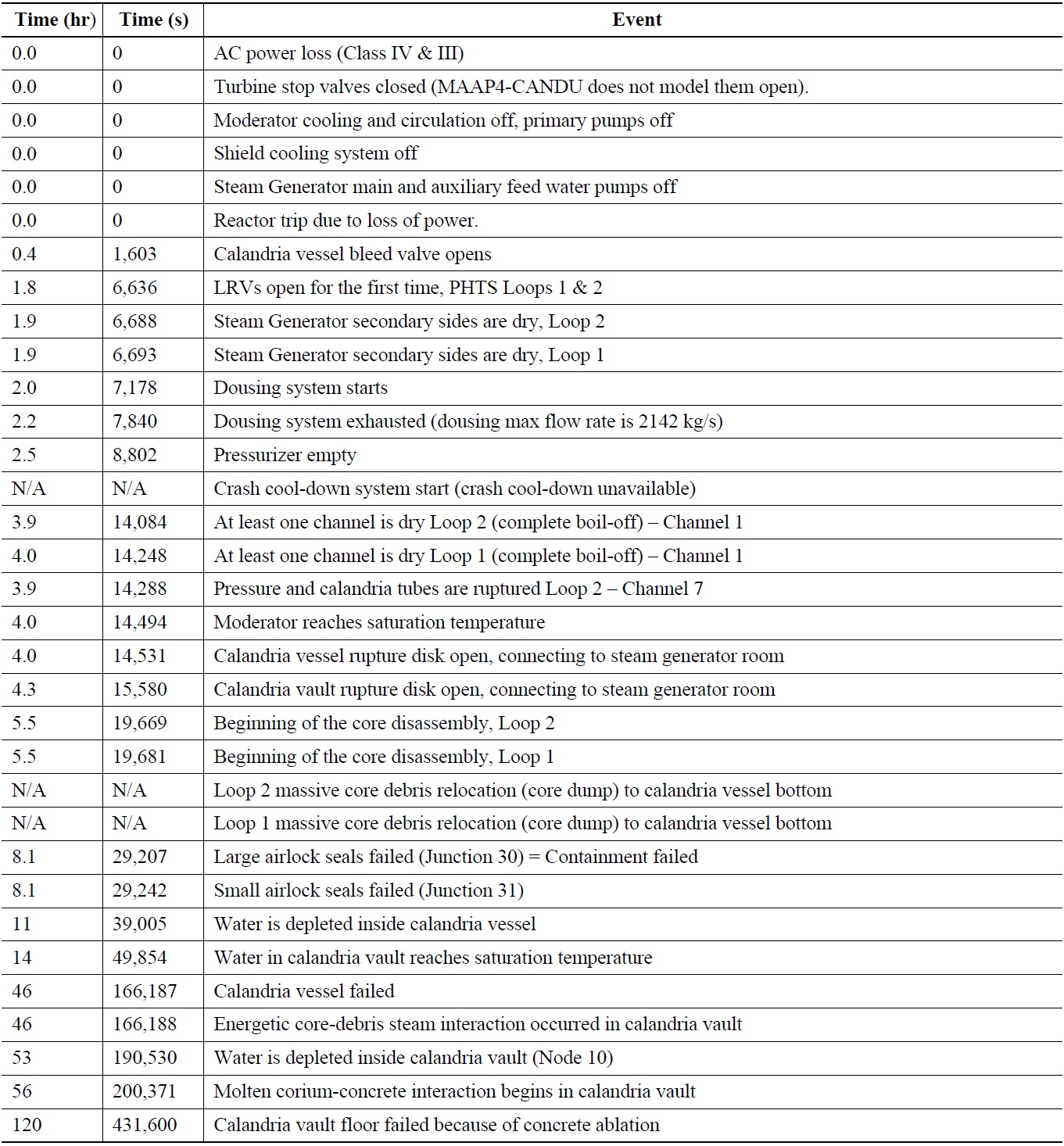
Sequence of Significant Events for a CANDU 6 Station Blackout
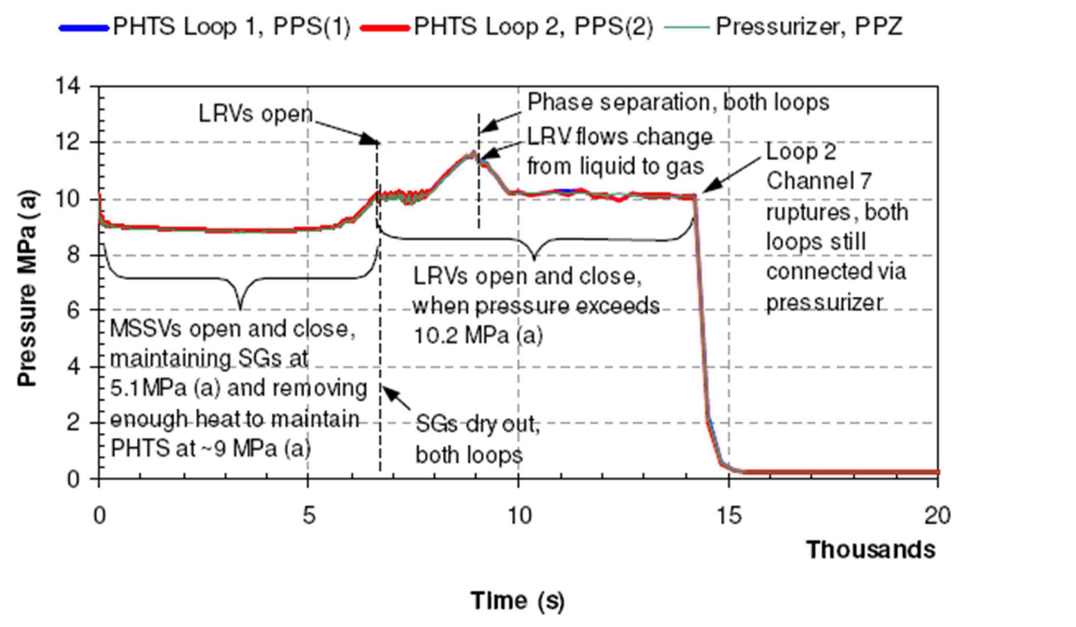
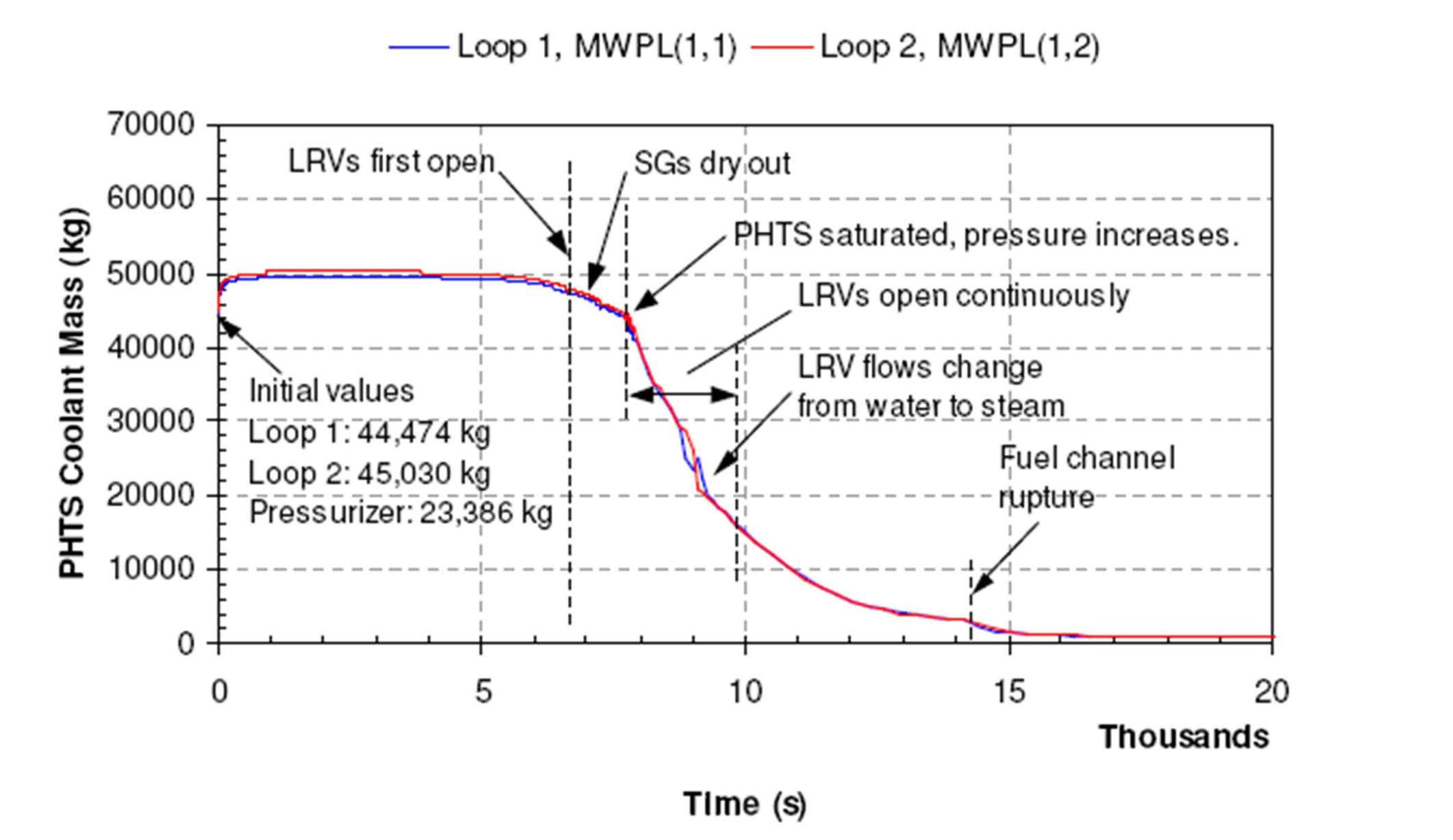
depressurizing the PHTS to ~9 MPa (Fig. 2). With the loss of decay heat removal by the steam generator secondary side, the primary coolant heats up and repressurizes. The PHTS liquid relief valves (LRV) open and close, venting primary coolant into the degasser condenser (Fig. 2). The degasser condenser pressurizes and vents to the containment and the containment pressurization initiates dousing. The fuel is uncovered and heats up as the PHTS inventory decreases (Fig. 3). The dry fuel channels overheat and one or two rupture, depressurizing the PHTS.
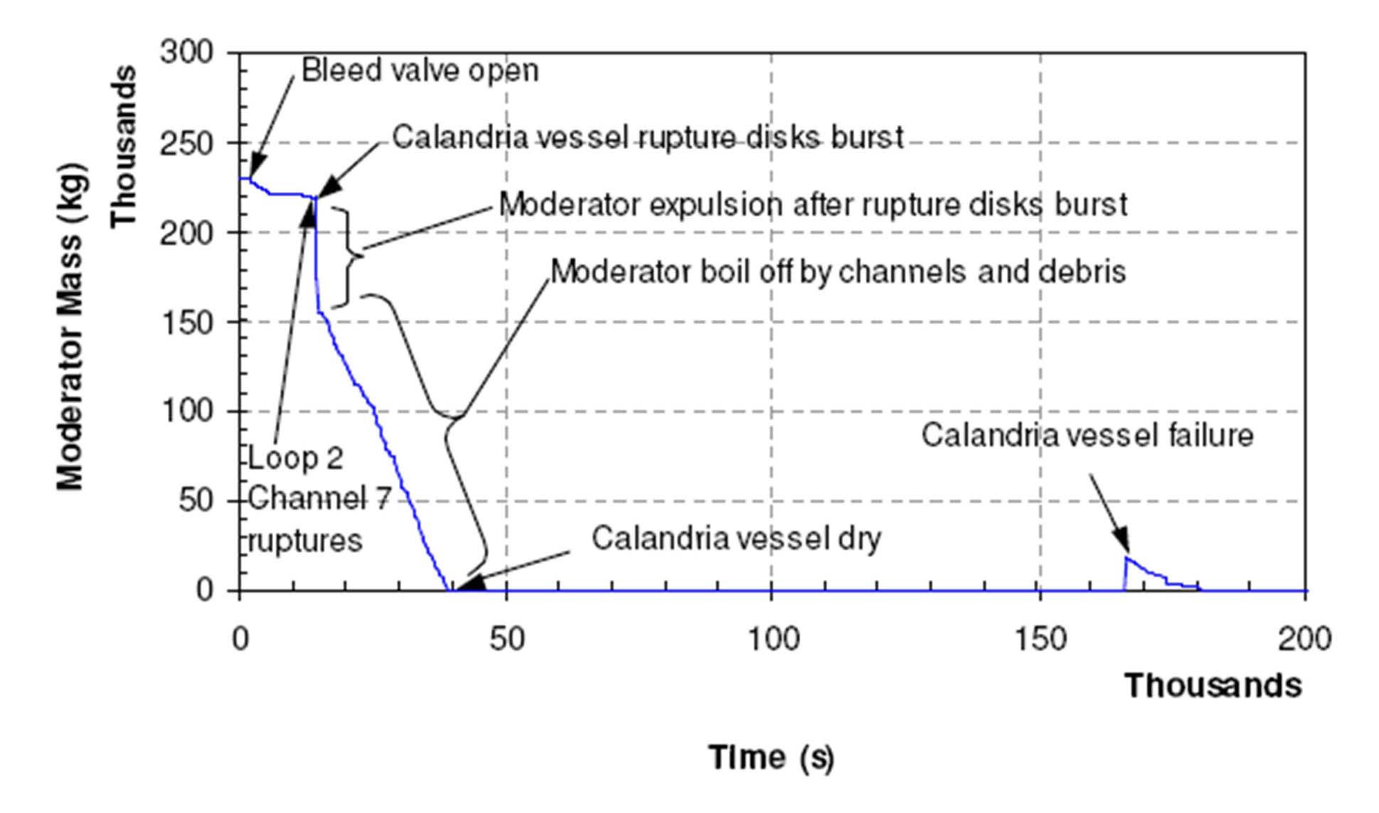
Moderator from the calandria vessel is partially expelled when a fuel channel ruptures and pressurizes the calandria vessel, bursting the rupture disks in the calandria vessel relief ducts (Fig. 4). The top fuel channels are uncovered
by the loss of moderator. Because these fuel channels are no longer cooled inside or out, they overheat, disassemble and sag onto lower intact channels still cooled by the remaining moderator. Some debris relocates to the bottom of calandria vessel, where it is quenched by the remaining moderator. The hot suspended debris and sagged channels can exceed the load supportable by the cool intact channels, at which time the majority of core drops to bottom of calandria vessel
in a rapid core collapse. In the current simulation, the suspended debris never exceeded the criterion for core collapse, so the debris relocation to the bottom of the calandria vessel occurred more slowly, without a sudden core collapse.
The moderator boils off due to the decay heat from the debris (corium) at the bottom of the calandria vessel (Fig. 4). The calandria vault water cools the external surface of the calandria vessel, which in turn cools the core debris even after the moderator has boiled off. The corium decay heat boils off the calandria vault water (Fig. 5). As the calandria vault water level decreases, more of the calandria vessel is uncovered and heats up due to convection and radiation heat transfer from the corium. The calandria vessel is assumed to fail when the calandria vault water level decreases below the elevation of the top of the debris in the calandria vessel. The core debris then relocates onto the calandria vault floor. The remaining vault water boils off, leading to molten core concrete interaction and the eventual melt-through of the calandria vault floor. The molten corium relocates to the reactor building basement, where it is quenched by the water that drained there from containment (i.e., PHTS water lost through the LRVs, moderator lost through the relief ducts, plus steam that condensed on containment heat sinks). Additional events are listed Table 2.
3. THE EFFECTIVENESS OF HEAT SINKS IN CANDU REACTORS FOR PROLONGED STATION BLACKOUT ACCIDENTS
CANDU reactors have a distinct advantage over other reactor designs with respect to multiple water reservoirs, already in place, that act as heat sinks during prolonged station blackouts until external water supplies can be established. These water sources, in the order of their depletion during a station blackout sequence, are the: (a) light water inventory in the secondary side of the steam generators, (b) heavy water primary coolant, (c) heavy water inventory in the emergency core cooling system, (d) heavy water moderator in the calandria vessel, and (e) light water inventory in the calandria vault and end shields. The total amount of water in these reservoirs is approximately 1,283 tonnes. The provision of these intermediate alternate heat sinks in CANDU reactors makes the uncertainties in severe core damage behaviour inherently less important while the progression of accident is relatively slow.
During a station blackout sequence the first heat sink available to cool the fuel is the volume of water in the PHTS. The PHTS ability to cool the fuel, however, is coupled to the availability of water in the steam generators; as long as the steam generator secondary side is maintained with an adequate inventory of water, the primary heat transport fluid effectively transfers the decay heat to the steam generators. The heat transport system pumps run down and provide forced circulation through the PHTS for the first few (high power) seconds. The decay heat in the channels and the cooling in the steam generators produce a density difference in the primary heat transport fluid, which induces natural circulation. This circulation removes the decay heat from the core to the steam generators. Natural circulation in the PHTS has been confirmed to be an effective heat removal mechanism in pressurized heavy water reactors [8].
In the steam generators, the secondary side water boils and the steam (and heat) is discharged to the atmosphere via spring-loaded main steam safety valves. Figs. 1 and 2 show that for about 1.9 h, the steam generator secondary side inventory boils off, effectively removing the decay heat from the fuel and depressurizing the PHTS to approximately 9 MPa.
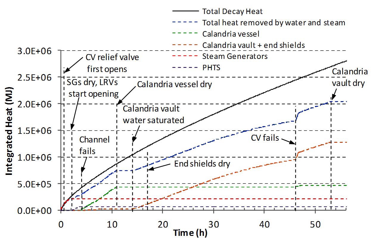
Fig. 6 shows a comparison between integrated decay heat and the heat removal capacity of various heat sinks available in CANDU reactors. The integrated heat is a convenient way to illustrate how the heat input and output behave when only the passive heat sinks within the reactor are available. Ideally, the integrated fission product decay heat curve (solid black line) should coincide (or be lower than) the total heat removed by the heat sinks (dashed blue line) during a severe accident. All of the decay heat will not be in the fuel, because fuel sheath failures and fuel heat up will release some fission products into the PHTS, to be subsequently transported into the calandria vessel and then the containment; however, even with additional fission product releases from hot debris in the calandria vessel, the majority of the decay heat continues to be generated in the corium, wherever it is located.
The dashed lines in Fig. 6 show the heat that is removed by the water and (mainly) steam that are expelled from various systems through the PHTS LRVs, calandria vessel relief ducts and relief valves, calandria vault relief duct, and steam generator relief valves. The heat removed by the steam generators (red-dashed line) is calculated by MAAP4-CANDU and then integrated using an Excel spreadsheet. The other three dashed lines (the calandria vessel, calandria vault + end shields, and the PHTS fluid) are estimates using the MAAP-CANDU calculations of the specific heat and mass flow rates of steam and water crossing a boundary. The heavy blue dashed line is the sum of the four light dashed lines described above (i.e., the sum of heat removed by the sensible heat of water and the latent heat in generating steam). The heat absorbed by large water masses as sensible heat in the calandria vessel and reactor vault will not appear in these calculations because the control volume boundary used for the calculations is the calandria vault surface.
Fig. 6 shows that, until the steam generators dry out, the decay heat is completely removed from within containment, except for a small loss through the primary heat transport piping to containment and a small amount to the end shields and moderator. The steam generators initially remove more than the decay heat, making the primary coolant subcooled and thus depressurizing the PHTS to ~9 MPa (Fig. 2). As illustrated by this analysis, the most effective heat removal strategy that could mitigate the consequences of a station blackout would be to establish adequate water make up to the steam generators and ensure that they do not dry out.
The steam generator secondary side boils dry at 1.9 h, ending the heat sink for the PHTS. The PHTS pressure increases from ~9 MPa to 10.16 MPa by 1.8 h (Fig. 2) and the coolant mass begins to decrease (Fig. 3) as the LRVs open and close, discharging two-phase primary heat transport fluid to containment and preventing the pressure from
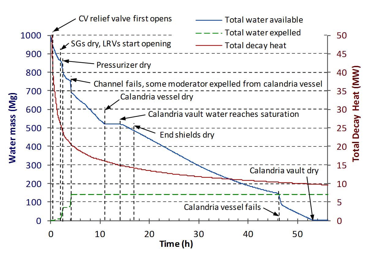
rising further. As a result, the primary coolant inventory decreases more rapidly as coolant is discharged (Fig. 3). As the water inventories decrease, fuel begins to be exposed and begins to heat up. The fuel channel ruptures, due to high PHTS pressure coincident with high fuel channel temperatures. The PHTS rapidly depressurizes (Fig. 2) due to the channel rupture and the water mass in the PHTS decreases further to less than 2,000 kg/loop (Fig. 3). Fig. 7 shows the water mass available as heat sinks are depleted during the accident progression in comparison with the total decay heat generated.
The mismatch between the integrated decay heat generation and the integrated total heat removal (Fig. 6) occurs after the steam generators dry out. This mismatch causes the integrated total heat removal curve to be approximately 1.4 x 10⁵ MJ less than the integrated decay heat, by the time the channel ruptures. The total heat removal curve then runs in parallel with the decay heat curve, since the moderator boil off matches the decay heat generation until the moderator is depleted at 11 h. Since the decay heat is not being absorbed by other heat sinks during this time (i.e., debris heat up), it indicates that the decay heat in the calandria vessel is less than the total decay heat curve, probably because of heat storage in the form of sensible heat up to the saturation point in the moderator and some fission products transported out into the containment. As can be seen in Fig. 6, restoring a heat sink capability with additional water (e.g., steam generator makeup prior to loss of primary coolant, calandria vessel refill after channel rupture) could increase the total rate of heat removal so that the heat removal curve would again coincide with the integrated decay heat generation (or be maintained in parallel). In the Enhanced CANDU reactors provisions are made available, through the severe accident recovery and heat removal system, to supply makeup water during emergencies.
During the early stages of the accident progression, the moderator slowly heats up because of the loss of the moderator cooling system and the addition of heat from
the fuel channels (conducted across the gas-filled fuel channel annulus). As the moderator is heated, the thermal expansion increases the pressure difference between the calandria vessel and containment, causing the moderator bleed valves to open and close. Fig. 4 shows the moderator mass. The channel rupture pressurizes the calandria vessel until the calandria vessel rupture disks in the relief ducts burst at 4 h. The calandria vessel pressure decreases to the moderator saturation pressure, so the moderator begins to boil vigorously; the turbulent boiling generates a large amount of two-phase fluid that is expelled out of the relief ducts. The result is that approximately 70,000 kg of moderator (i.e., water) is ejected out the calandria vessel along with the steam (Fig. 4). The loss of moderator by this route decreases the volume of the heat sink available for fuel cooling; however, the remaining moderator inventory boils off over a period of several hours (11 h), successfully maintaining the debris in a cooled state.
Following the calandria vessel dry out, the total heat removed (Fig. 6) remains constant at ~7.5 x 10⁵ MJ for approximately 3 h, until the calandria vault water becomes saturated and steam starts leaving the calandria vault. The large volume of water in the calandria vault can absorb approximately 2.15 GJ of heat (4.186 kJ/kg x 514,000 kg) for every degree of temperature rise. The decay heat is ~15.5 MW at the time, and some decay heat is used by the corium heat up and melting, so the calandria vault water heats at less than 1℃ per 140 s. Thus it takes ~3 h after moderator boil off for the vault water to reach the saturation temperature at ~14 h.
After the calandria vault water reaches saturation, the total heat removal rate increases again, however, the slope of the curve is still less than the integrated decay heat curve (Fig. 6). This indicates progressively distressed cooling and corium temperature escalation, although it must be recalled that the integrated decay heat curve represents all the decay heat, including the decay heat deposited in containment by fission products transported out of the calandria vessel. The water inventory in the calandria vault boils for about 32 h until the calandria vessel fails at 46 h. Until this time, the core is maintained in-vessel, although the top of the calandria vessel becomes uncovered at 29 h, and the vessel is progressively uncovered. This reduces the size of the heat sink seen by the top of the corium, as well as allowing the uncovered portions of the calandria vessel to heat up.
After the calandria vessel fails at 46 h, the corium is assumed to pour into the calandria vault, where it is quenched by the remaining water. Molten corium-concrete interaction begins at 56 h, after the remaining calandria vault water has boiled off.
The slow progression of the station blackout sequence described above provides sufficient time for operator action to add water into the reactor (calandria vessel or calandria vault). As shown in Fig. 6, at the time of calandria vessel failure, the total heat removed is approximately 0.8 x 10⁶ MJ below the integrated decay curve. This is equivalent to about 350,000 kg of water evaporating at atmospheric pressure (hfg = 2260 kJ/kg). If 350 tonnes of water was available at this late stage of the accident, it would be sufficient to (almost) refill the calandria vault, and thus delay the calandria vessel failure by over 30 hours (recalling that the decay heat is declining continuously). Of course the reactor would still be damaged, with a large debris bed in the bottom of the calandria vessel. If 350 tonnes of water were available at the beginning of the accident, it could delay steam generator dry out to ~14 hours from 1.9 h (including the effect of declining decay heat), providing much needed time to re-establish alternative power sources to restore cooling, and prevent reactor damage. In the current CANDU 6 reactors severe accident management measures ensure that additional water is made available for core cooling during emergencies. In the Enhanced CANDU 6 the reserve water tank has a capacity of ~2,040,000 kg, which can easily restore cooling to the steam generators, PHTS, calandria vessel and calandria vault.
At present, lake or sea water is the ultimate heat sink for heat from the turbine condensers and moderator cooling systems during NOC, while four types of alternate back up heat sinks exist within the containment for emergencies. The backup heat sinks can remove heat from the reactor core to the atmosphere (steam generators) or into the containment (all other heat sinks). The reserve water tank can provide an additional supply of water without requiring pumps. The water expelled from the PHTS LRVs and the calandria vessel, plus condensate from containment, can act as a temporary heat sink provided the water can be pumped back into required systems.
Thus in a CANDU reactor, a large inventory of water and multiple barriers have the inherent capability to prevent (or slow) corium debris falling onto the concrete floor leading to core-concrete interaction, during a severe accident. The slow progression of the accident provides adequate time for the operator to restore heat sinks and ensure fuel or debris cooling.
For a pressurized heavy water reactor, core damage accidents are grouped into two broad categories: limited core damage accidents and severe core damage accidents. The limited core damage accidents are typically considered as part of the design basis whereas the severe core damage accidents are considered beyond design basis accidents.
A station blackout case was analysed for a generic CANDU 6, using the MAAP4-CANDU computer code. Analysis indicated that the steam generators can remove the decay heat effectively for about 1.9 h, by boiling off water in the secondary side. When the steam generator secondary side dries out, a mismatch between heat generation and heat removal begins. The remaining heat sinks continue to boil off and remove heat at a rate lower than the decay heat generation, until the moderator in the calandria vessel is depleted at 11 h. The rate of heat generation and heat removed gradually diverge after 14 h. The last of the water inventories in the calandria vault begins to boil off at 14 h and the calandria vault water delays calandria vessel failure until 46 h. The difference between the heat removed by boiling off water inventories, and the integrated decay heat, is equivalent to the latent heat of ~350 tonnes of water, at the time of the calandria vessel failure. If this water is available at any stage of the accident to that point, it would significantly delay the accident progression, providing operators additional time to restore cooling systems. The most effective heat removal strategy during a station blackout would be to establish adequate water make up to the steam generators and ensure that they do not dry out. In the Enhanced CANDU 6 ~2,040,000 kg of water is available in the reserve water tank, for prolonged emergencies requiring heat sinks.