With oil price jumping and environmental issues, green ship is paid deep attention to by ship owner, operator, builder, class and government. Fuel efficiency and reduction of CO2 emissions are expected to have a strong influence on the design and operation of merchant ships. Therefore, many ship owner and operator are looking for the more economic method by seeking the best operating route and finding the application of reliable and effective energy saving devices. Furthermore, due to the Energy Efficiency Design Index (EEDI) in 2013, more than ever attention will be focused at achieving maximum fuel economy in the hydrodynamic design of hull forms and their propulsive appendages. So, every new built vessel has to meet a increasingly strengthened specific Energy Efficiency Design Index and the effective energy saving device is expected to contribute to making the low EEDI. So far a lot of new idea and patents have been proposed and tested, and some of them have been actually applied to various kinds of vessels.
This paper shows numerical and experimental design approach and study on an energy saving devices development, which is particularly able to apply to fuller ships such as mainly Tankers and Bulkers. The pre-swirl ducts including unconventional half circular duct and conventional circular duct were investigated for this study that is considered one of the most effective energy saving devices to support the propeller performance for the relatively fuller ship.
With design investigation, the resistance, self propulsion test and cavitation test have been conducted at Hamburgische Schiffbau- Versuchsanstalt (HSVA), located Hamburg, Germany. The optimum angle tests for the preswirl duct were performed at a design speed at design draft, and each measured ship performance was compared. After that, with optimum setting of the preswirl duct the general towing tank test was carried out at various speeds. Finally cavitation test and hull pressure measurement were performed at design and ballast draft with and without final pre-swirl duct respectively.
ENERGY SAVING DEVICE DEVELOPMENT
>
Energy saving device development flow
The various kind of energy saving devices has been reviewed, of which important part was incorporated in PNA compiled by The Society of Naval Architects & Marine Engineers (SNAME) and that of Carlton (1994). A very early paper in this respect, Van Lammeren (1949) designed and investigated nozzles ahead of propellers. Also the International Towing Tank Conference (ITTC) (1996) dedicated a lot to the hydrodynamics of unconventional propulsors and their treatment and scaling in model experiments that suffer from “scale effects” are worth to be revalidated. PBCF was proposed by a group of Japanese inventors, Ogura et al. (1988), as a means of increasing the efficiency of a ship screw propeller. Sparenberg and de Vries (1987) by using linear optimization theory designed and tested a 3-bladed end-plate propeller. For the special end-plate propeller known as the Contracted and Loaded Tip (CLT) propeller, Hollstein et al. (1997) outline the design of such a propeller for a bulk carrier and compare this with data for a sister ship fitted with a conventional propeller. Kappel propeller with integrated fins in the tip region (bent blade tips) Andersen (1996) carried out a comparative study with the conventional propeller actually fitted on the ship as a reference. Wake equalizing ducts were developed by Schneekluth (1986). Since 1984 MARIC has developed more than ten energy saving devices such as the composite device of simplified compensate nozzle (SCN) and Costa propulsion bulb (CPB), thrust shaft brackets (TSB), fore-propeller hydrodynamic fin sector (FPHFS) etc. (Qian et al., 1992a; Zhou and Zhao,1990; Qian et al., 1992b).
[Table 1] Summary of measures to increase propulsion efficiency (HSVA NEWSWAVE 2006/1).
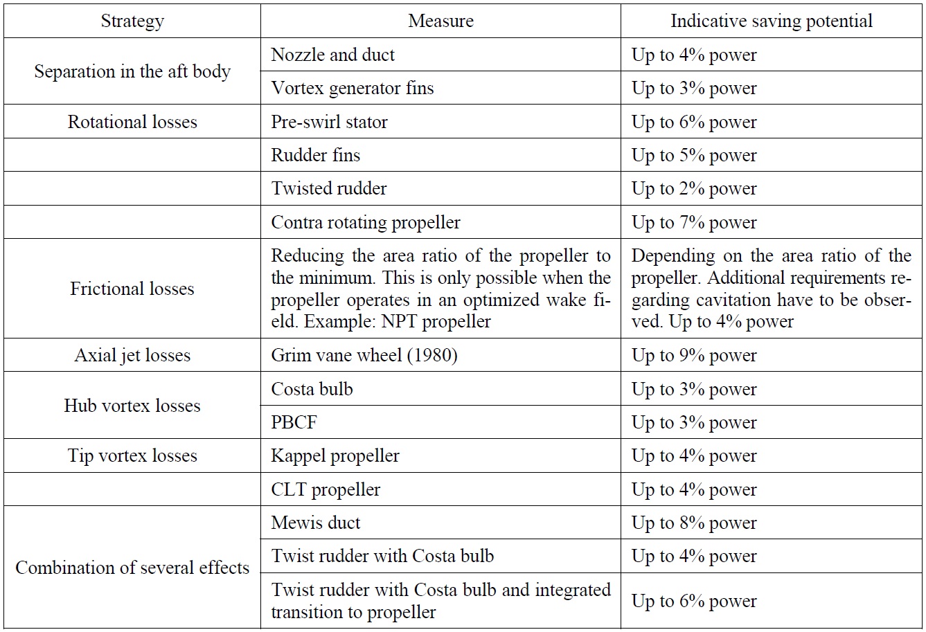
Summary of measures to increase propulsion efficiency (HSVA NEWSWAVE 2006/1).
Particularly, as oil price has been rapidly raised up recently, fuel oil saving devices is needed more necessarily, and various kinds of energy saving devices are devised and tested. Actually, according to maker’s claim, they are applied to actual operating fleets as well as new building vessels.
Along with this, many exploratory studies are preceded on the effects and working principles of developed energy saving devices using CFD and model test. Simultaneously research works to validate the real effect of energy saving devices are carried out as a form of joint industry project (JIP). For example, Refit2Save by MARIN is one of JIPs aiming at the quantifycations the effect of various commercial available retrofits for fuel consumptions on ships in service. The following table shows indicative saving potential based on the each energy saving devices’s characteristics from Mewis and Hollenbach (2006).
>
Fundamental study on propeller losses
Before the development of a certain energy saving device to improve fuel oil consumption, it should be considered which is more effective depending on the ship’s hydrodynamic characteristic and where would be better to be installed. Regarding the locations of installation, which can be basically divided by three basic zones according to energy saving device’s working principle. Some are located before the propeller, some at the propeller station and some behind propeller. Some of these fuel saving measures are designed to minimize ship’s vibration and have a favorable effect on the propulsion efficiency. Clearly some devices have conflicting operational function, but these three categories are very useful to broadly group the various device.
The device before the propeller is reacting with the final stages of the growth of the boundary layer around the stern of the ship, and the devices at the propeller station and behind propeller are working within both the hull wake field and the slipstream of the propeller, but they are all attempting to recover the energy loss so that increase propulsive efficiency. In this respect, many energy saving devices have a close relationship with the propeller, so firstly we have to think the efficiency and loss of propeller, what inherent losses are occurred and how to recover them if possible.
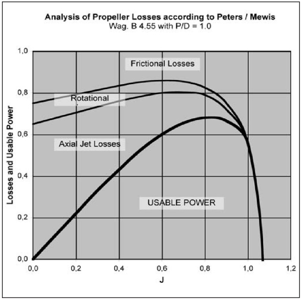
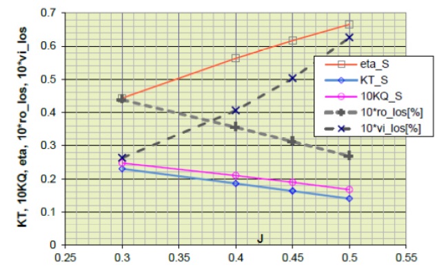
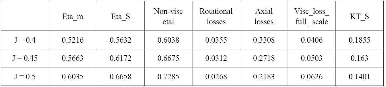
There exist largely 3 losses such as axial loss, rotational loss and frictional loss in the propeller. Among them, frictional losses is tried to reduce by the optimum determination of propeller main parameters such as an expanded area ratio. However, propeller rotational loss and axial loss are the items trying to recover their losses by the installation of additional propulsion devices. Practically, it is judged that designed propeller has been already optimized at design stage by reducing the wetted surface area considering the maximum efficiency based on reasonable cavitation performance. In this study, the rotational loss and axial loss were recovered by preswirl duct located before the propeller. As an example, the Fig. 1 shows the input power, the usable power and the different propeller losses for a Wageninger B-series propeller (B 4.55 with P/D = 1.0), according to Mewis and Peters (1986).
In this way, the actually designed propeller mounted behind the VLCC was analyzed how much improvement possibilities remain under open water condition using surface panel method and empirical understanding of full scale frictional loss, which states the losses in such a manner that the actual model scale or full scale efficiency and the sum of losses would arrive at 100%. For the reference, viscous losses are derived from eta_S ?etai, where etai is the inviscid efficiency obtained by Blade Element Momemtum (BEM) prior to any correction for surface friction. For the correction to full scale efficiency from BEM results, section drag coefficients derived via skin friction only were used.
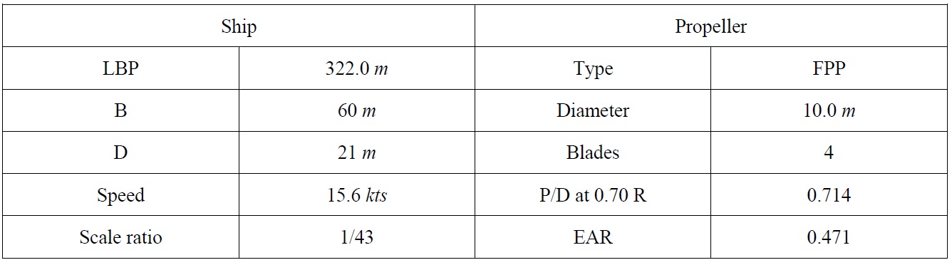
[Table 2] Main particulars of ship and propeller.

Main particulars of ship and propeller.
KT_S = 0.163 is supposed to be valid for the design propeller behind the bare hull at design speed. In the Table 3, the detail figures for KT_S = 0.1855, KT_S = 0.163 and KT_S = 0.1401. At KT_S = 0.16 followings are stated,
(1) Frictional losses range around 5% for full scale is hardly recoverable and much smaller than the axial losses. The relatively low level of viscous losses is explained by the comparatively small expanded area ratio of propeller of this vessel.
(2) The rotational losses are roughly of the same order as the frictional losses in full scale. To a certain amount they should be recoverable by pre- and post swirl devices.
(3) Axial losses cover typically 27% and they represent the largest contribution in this case. They are directly related to the thrust load coefficient CTH.
(4) Losses due to in-homogeneities 2% is roughly taken from 1-(rotational loss)-(axial loss)-(ideal efficiency).
[Table 3] Separated losses for design propeller between J = 0.4 and J = 0.5.
Separated losses for design propeller between J = 0.4 and J = 0.5.
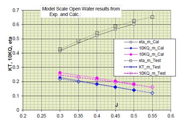
The sum of full scale efficiency, viscous losses, rotational losses and axial losses comes close to one. It is considered that the remaining 3% may be due to in-homogeneities. The rotational losses are about 3.1% at the J = 0.45 condition which would be related to the propulsion state of the propeller. The viscous and rotational losses expected in full scale have been plotted together with the usual (full scale) open water data in Fig. 2. The comparison of the model scale panel method results and the measured open water performance is given in Fig. 3.
Eta_S Full scale propulsive efficiency
KT_S Full scale thrust coefficient
KQ_S Full scale torque coeeficient
Vi_los Viscous loss of propeller
Eta_m model scale propulsive efficiency
KT_m model scale thrust coefficient
Ro_los Rotational loss of propeller
Etai Ideal propulsors efficiency
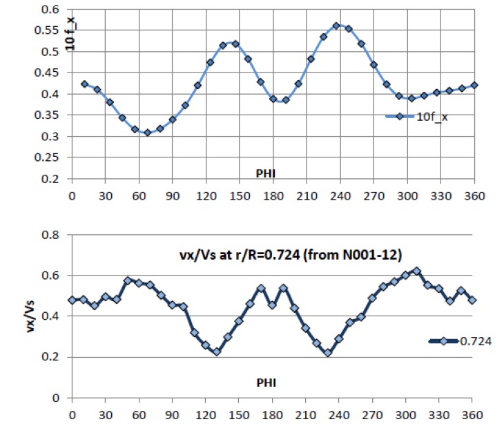
For the propeller operating in behind, extra losses due to inhomogeneous loading of the blade depending on the blade angular position to be mentioned:
(1) Load changes due to change of axial flow component.
(2) Load changes due to change of tangential flow component along the circumference.
From Fig. 4 one may identify ‘high frequency’ fluctuations of the blade forces, i.e. changes from thrust maximum to thrust minimum within about 60° blade angles. Such a behavior will cause a pronounced shedding of vortex structures that are not contributing to the mean axial flow in the slipstream, which makes energy losses. In addition any load-hump will cause highly accelerated flow at the leading edge of the blade, which may invoke separation and increase the pressure resistance of the blade temporarily.
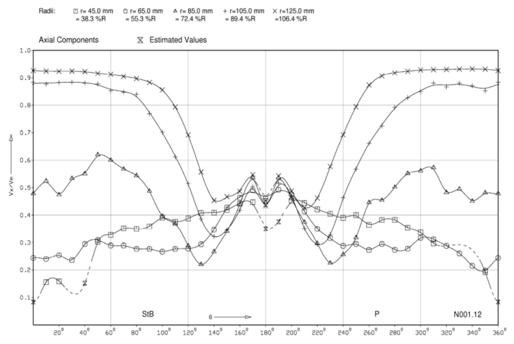
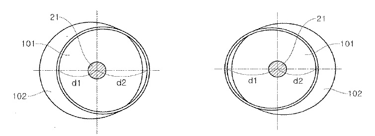
Finally, any inhomogeneity of the thrust load distribution on the propeller disk will be worse than a uniform spreading. To get an impression for the thrust load on the disk the one blade graph is not totally sufficient, as it does not resolve for the radial direction.
Recoverable losses should be associated to the mean tangential and axial flow. Pre- or post-swirl devices are trying to eliminate the mean tangential flow of the propeller slipstream. Generally a widening of the slipstream, which requests a duct type device, would give some axial losses back. And, taking also the thrust inhomogeneity into account, the following targets can be identified that an upstream duct should work on:
(1) It should give a pre-swirl to the propeller.
(2) It should widen the slipstream.
(3) It should homogenize the axial flow and the cross flow heading for the propeller. In the particular case of this VLCC hull, it seems worthwhile to equalize the flow around 140° and 240°.
>
Various kind of duct design ideas
Several ideas are devised and reviewed briefly below for more efficient Duct design, and applied to the patent.
(1) Eccentric duct: This idea is to put a symmetrical duct not parallel to the shaft line or apart from shaft line. This idea can be useful to guide the flow into certain areas of the propeller disc. And it may be expected to have a positive influence on axial wake peak and to increase effective wake value by increase of tangential wake component like asymmetric aft hull form.
(2) Asymmetric profile angle of upper and lower duct: This idea can be considered useful to guide the flow into a preferred direction and to reduce the resistance caused by lower duct. Another useful effect may accelerate the axial flow non-uniformly so that outflow could become homogeneous. This latter function could be helpful to influence the wake peak in the 12’o clock position positively.
(3) Tilting duct: The tilting duct is close to the idea2 (the asymmetric duct). Duct shape is symmetric, but gives an angle of inclination for installation. It could however probably easier been manufactured.
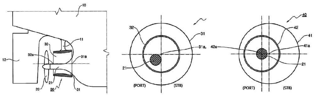
(4) Inclined half circular duct: In case of a right turning propeller, port side upcoming flow could be re-circulated against propeller rotational direction and star-board side upcoming flow not to be disturbed. So this idea may be promising to increase the propulsive efficiency.
>
Optimization of duct concept by numerical investigations
Viscous flow computations were performed using HSVA code FreSCo+ which is based on the finite-Volume method. The governing equations for viscous flow are the Reynolds-Averaged Navier-Stokes (RANS) equations. The RANS-model includes the equations for conservation of energy, momentum and the equations for turbulence modeling. The physical solution domain is subdivided into a number of contiguous control volumes - the computation cells, establishing unstructured hexahedral mesh. A rectangular computation domain was chosen. The mesh contains about 2.92 million cells. The grid generated is an unstructured hexahedral mesh with mostly cube elements and cube elements with hanging nodes at the transition layers.
The boundary layer was modeled as o-grid, inflated from the model boundary with exponential spacing. It starts off the surface with tiny first spacing to approximate the linear part of the BL, the viscous sub-layer, to meet y+ values around 50 for the applied wall function. Meanwhile, a grid refinement study did not performed, because the aim of CFD calculation for this study was basically to get the initial optimum design of preswirl duct that would be improved at the model test stage for best optimum configuration. But, a lot of cells as possible were tried to put in the vicinity of the duct and the followings were paid attention to
(1) The pressure distribution on the duct surface how close they would relate to prior BEM-results from the design stage.
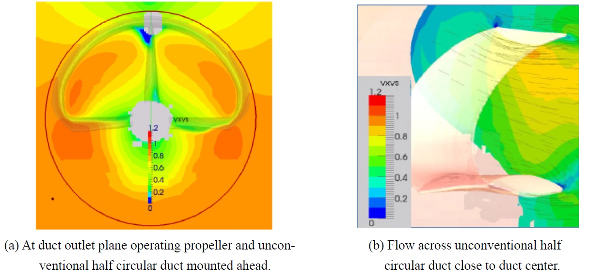
(2) The velocity distribution taken at the duct outlet plain which was supposed to be much more homogeneous compared to the bare wake.
For the present project a free surface calculation was performed and simple two equation of turbulence model was used, the k-ω SST Model. Subsequently exactly 62.9
The propeller action was accounted for using the body force method. The considered speed was 15.6
A duct is a complex device operating in a complex environment to improve propeller operation, particularly to increase the propeller efficiency. Having identified the propeller losses in the above, some characteristics of the flow at the duct may be recognized and some attempts may be tried to influence the flow at the duct outlet as follows.
(1) As a native function of the duct, it can accelerate the flow so that generate thrust itself. Ducted propeller leads to a reduced thrust load coefficient of the rotating blades.
(2) The duct should ideally remove the in-homogeneities denoted to the axial component. A propeller design could be reconsidered with respect to the propeller parameter such as a expanded area.
(3) In addition, in-homogeneities denoted to the tangential flow to the propeller are reduced.
(4) Duct inside section should be cambered. This should assure that the duct accelerates flow into propeller.
In addition, duct is required in design to show no shedding vorticity and no related losses. Besides keeping the circulating flow on a constant level along the duct, it should be also considered to control the self-induced axial flow at the duct outlet for a favorable performance of the duct. This constancy of the axial self-induction will be shown up in the ships wake under the influence of the propeller. And, in order to keep the frictional losses as low as possible, the appropriate inclination of the duct section is decided, which is derived from the analysis of ships wake filed characteristics and the action of the propeller.
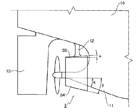
Furthermore, propulsive efficiency can be increased by making a preswirl flow into the propeller plan in advance. Even though rudder has also swirl recovery ability, however the rudder blade does not cover the horizontal direction. In this respecttive, haft circular type duct combining the duct with a pre-swirl ability was considered. In parallel, a conventional duct type with fin was studied for comparison.
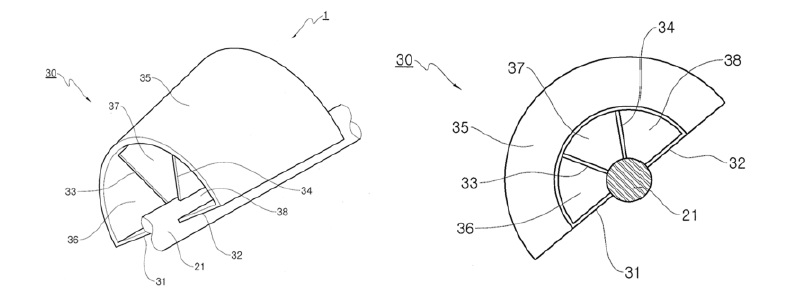
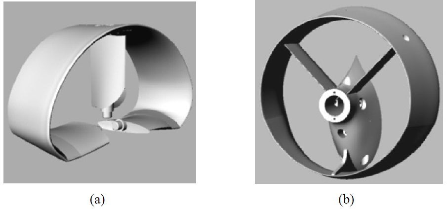
First, the unconventional half circular duct consists of 3 basic parts, namely a large upper semi-circle part, a nearly horizontal part and center fin part. (Fig. 11(a)) In total it covers the upper half circular area of the propeller plane, being connected to the hub with its horizontal parts at port and starboard side. Especially the sharp edge between wing part and duct ring was made round to smooth transition and half circular duct was designed for the axial flow to be homogenized as proposed already in above. The targets for this duct design are a compensation of an upper/lower-asymmetry of the bare hull wake at the propeller disk and making a preswirl flow in advance against propeller rotational direction. The asymmetry in wake distribution can hardly be compensated by the propeller design only. The single blade thrust will be increased at the 12’o clock position and the upper propeller disk will thus be highly loaded. Normally, it would be more efficient to make a propeller disk loading more uniformed.
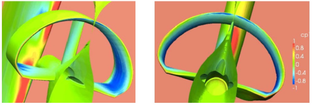
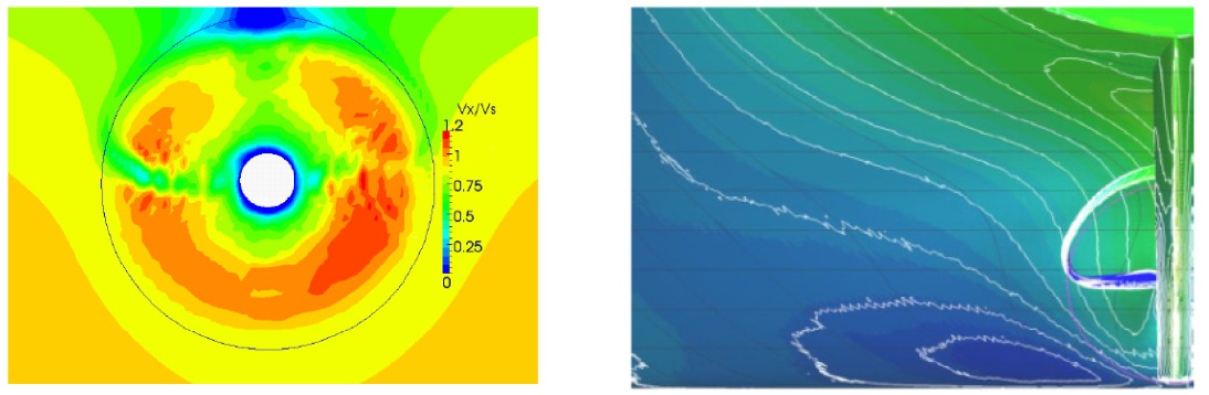
The CFD calculations were performed to find out the effects of wings and duct. CFD results show that the stagnation pressure line almost coincides with the leading edge (Fig. 12). Fig. 13 gives contours for the total axial velocity at the duct outlet plane. Here the total axial component is defined as the axial component obtained by activated body force propeller model. Inside the duct the acceleration effect is prominent but the level is not significantly diminished at the outlet, which means the inflow at the entrance of duct go through the duct to the trailing edge well without separation. This appeared to be a crucial detail point for the proper design of duct sections. Moreover an integration of surface forces acting on the duct gave a support of the propeller thrust by about 1.3%.
Second, the conventional circular duct has been studied in the same way. The target of the conventional circular duct (Fig. 11(b)) was to compensate primarily a strong non-uniformity in radial direction which is a characteristic appearing generally in the measurements of the bare hull wake for fuller ship. To arrive at accelerated flow at the duct outlet, the sections were cambered to the inside, which amount of camber was adjusted to give a reasonable accelerated flow at the duct outlet. In addition, duct was designed to avoid estimated separation effect.
Especially in its lower part of conventional circular duct, an enlarged clearance to the stern bulb was given. This feature was shown in Fig. 14 by shortening the duct section chord length at the bottom.
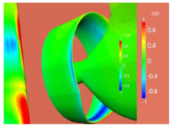
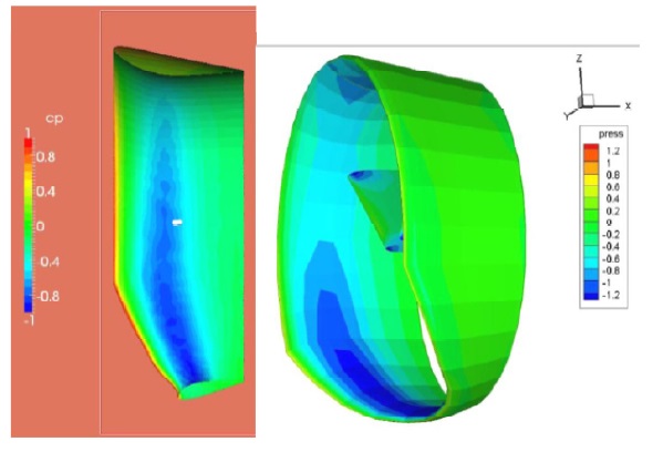
The same section type was used for the unconventional half circular duct as well. RANS calculations were repeated as an unconventional half circular duct at model scale. One of the basic design targets is to meet the target surface pressure coefficient. It resulted from panel method calculations, changing geometry by try and error until the target pressure distribution was achieved. And, the target pressure was checked by RANS analysis using body force method. Fig. 15 gives the pressure coefficient on the inside of the duct obtained via panel method (right) and RANS analysis (left).
A small deviation may be recognized from Fig. 14 that is on the pressure at the duct outside. A small area close to the duct leading edge can be identified where low pressures (Cp negative) appear on the outside. It may be resulted from the constraint condition which conflicts with the optimum angle of upper duct due to the difference of flow velocity between two areas, i.e., it is very difficult to avoid this negative pressure at the duct outside with circular duct shape due to non circular wake distribution. Moreover, it linked to the propeller rotation effect so that those deviations would be larger. Therefore, the eccentric duct and tilting duct idea in the Figs. 6 and 8 may be good alternatives to be investigated considering it depends on the duct diameter and center position. For displaying the pressure on the duct surface, the ship speed based pressure coefficient
>
Optimum configuration test for unconventional half circular duct
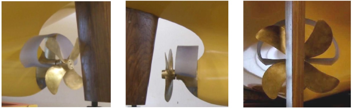
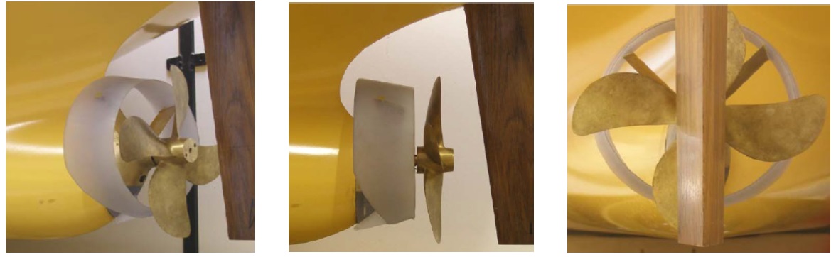
The optimum test to find the best configuration of duct was carried out with unconventional half circular duct and conventional circular duct. Both preswirl ducts were made of plastic material using 3D scanned printer. The ship model was built of wood to a scale ratio of 1:43. The tested speed was at 15.6
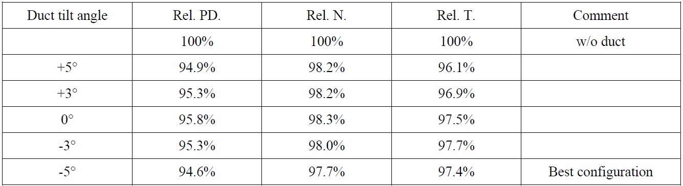
In case unconventional half circular duct, in order to get best saving effect in propulsion optimum self propulsion tests were performed with changing duct angle of inclination from +5° to -5°. The “+” angle means the top of duct is more remote from propeller and on the contrary the “-” angle means the top of duct trail edge is closer to propeller. Unfortunately, duct and wing fins could not work separately divided into 2 parts due to the manufacturing matters. So, when the inclination angle is given, duct angle and wings of port and starboard were changed together.
Comparing to the results of opt. self propulsion tests in Table 4, the -5° configuration gave the largest propulsive energy saving effect by 5.4%. It is considered that the horizontal fin might have changed tangential flow downward strongly at76; tilt angle. Due to the lack of test time and prepared test conditions, model test stopped at -5°, the lowest point is not clear. But, depending on the tested results,76; is judged by the best configuration.
Even though the optimum design was found by trial and error in advance using numerical analysis, it may need to carry out optimum angle test to find the best configuration. Finally self propulsion test and cavitation test was carried out with the final best configuration.

Relative power consumption, propeller rotation, thrust for unconventional half circular duct.
>
Optimum configuration test for conventional circular duct
With same condition as unconventional half circular duct, the optimum angle test to find the best configuration of duct was carried out with conventional circular duct. However, conventional circular duct unlike the unconventional half circular duct manufactured to rotate the fin having various pitch angles and tilt angle of duct was fixed.
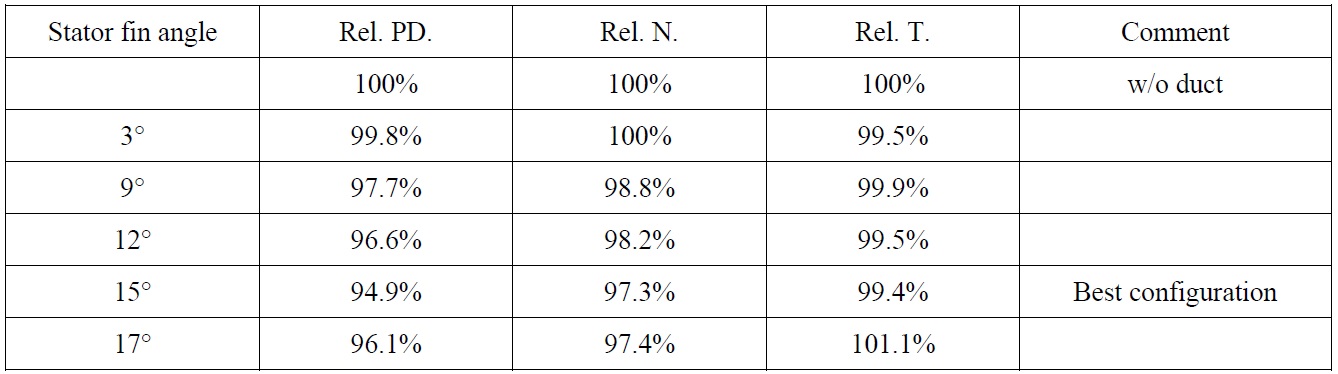
[Table 5] Relative power consumption, propeller rotation, thrust for conventional circular duct.

Relative power consumption, propeller rotation, thrust for conventional circular duct.
Comparing to the results of opt. self propulsion tests in Table 5, the 15° rotation of stator fin was considered the best configuration. Abt. 5.1% efficiency gain was obtained. Due to the limited test scope, only same pitch angle cases between port and starboard stator fins were tested. However, if each pitch angle is adjusted separately in detail, the saving effect could be obtained better.
The tests were carried out in HYKAT, the largest cavitation tunnel of the HSVA. Its test section is 11
Four test conditions were tested to compare the cavitation at the propeller behind the bare hull and behind unconventional half circular duct. The tested drafts conditions are design draft (forward draft TF = 21.0
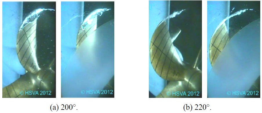
The unconventional half circular duct was considered as the best configuration judging from the optimum towing tank tests. So, for the adjustable duct the same hardware and the same tilt angle were used that characterized the best performing device found from comparative towing tank experiments. The condition without duct were tested as well and compared with that of unconventional half circular duct mounted upstream of the propeller. The primary interest was the influence of the unconventional half circular duct on propeller cavitation.
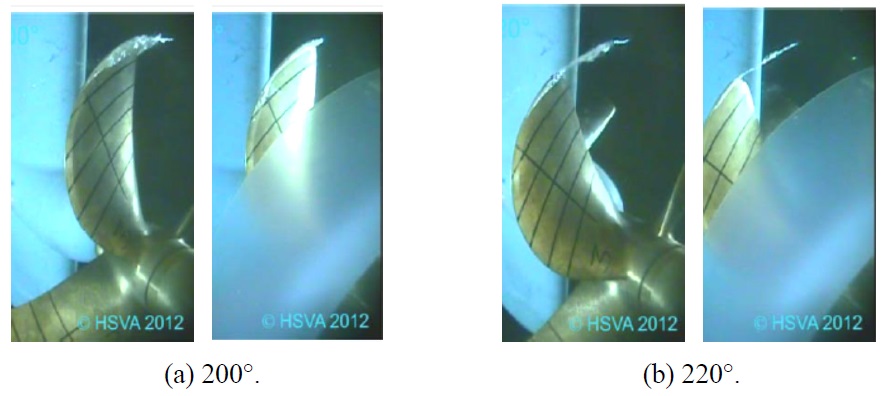
As shown Figs. 18 and 19, compared to the bare hull case, the unconventional half circular duct showed a favorable influence on cavitation extent and cavity volume both at the design and ballast drafts. The cavitating tip vortex behaved smoother when the duct was mounted.
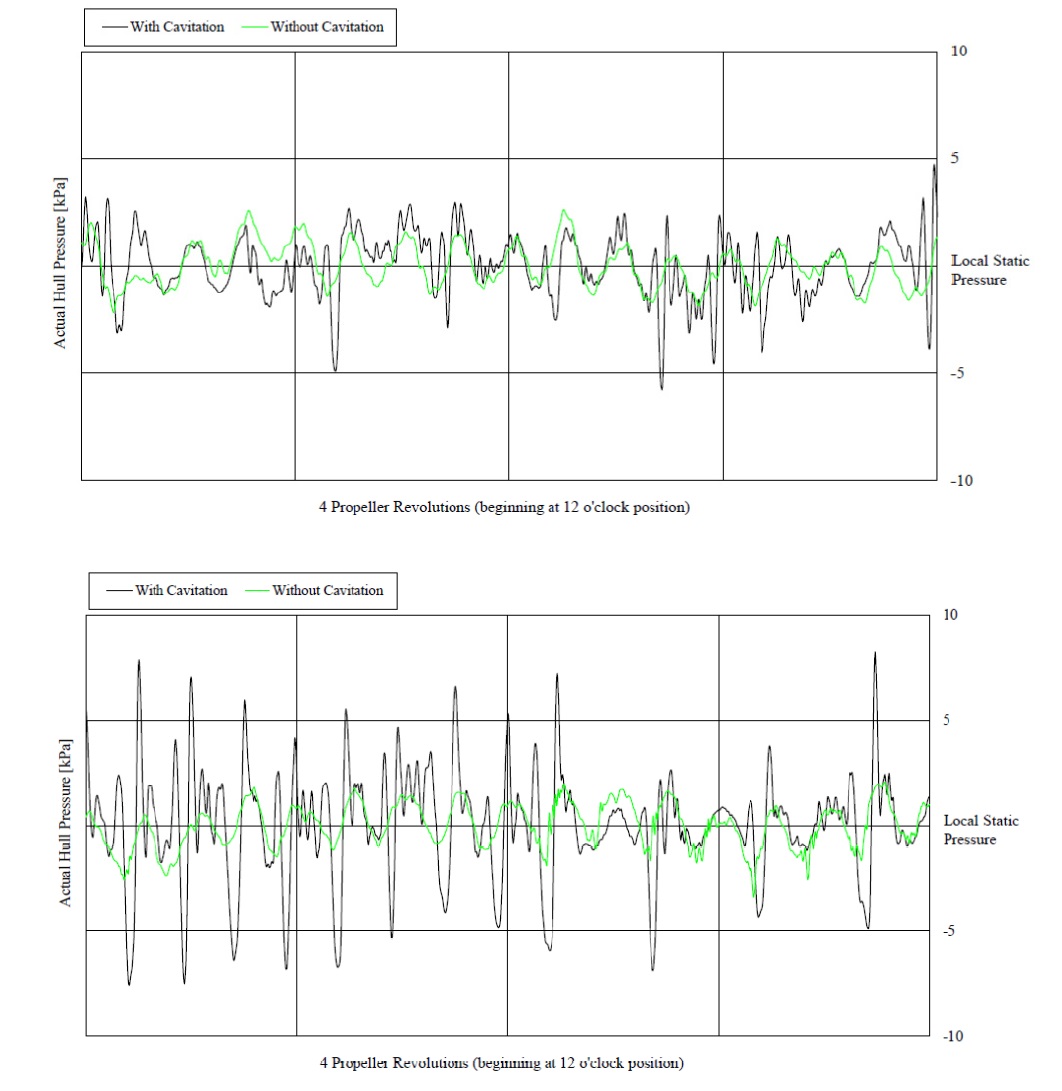
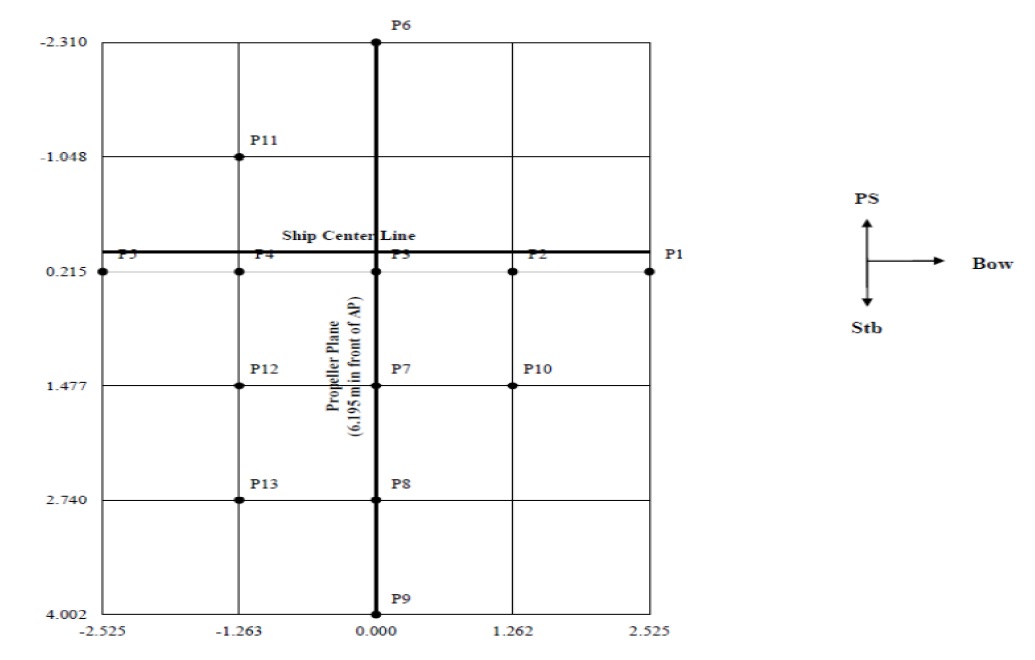
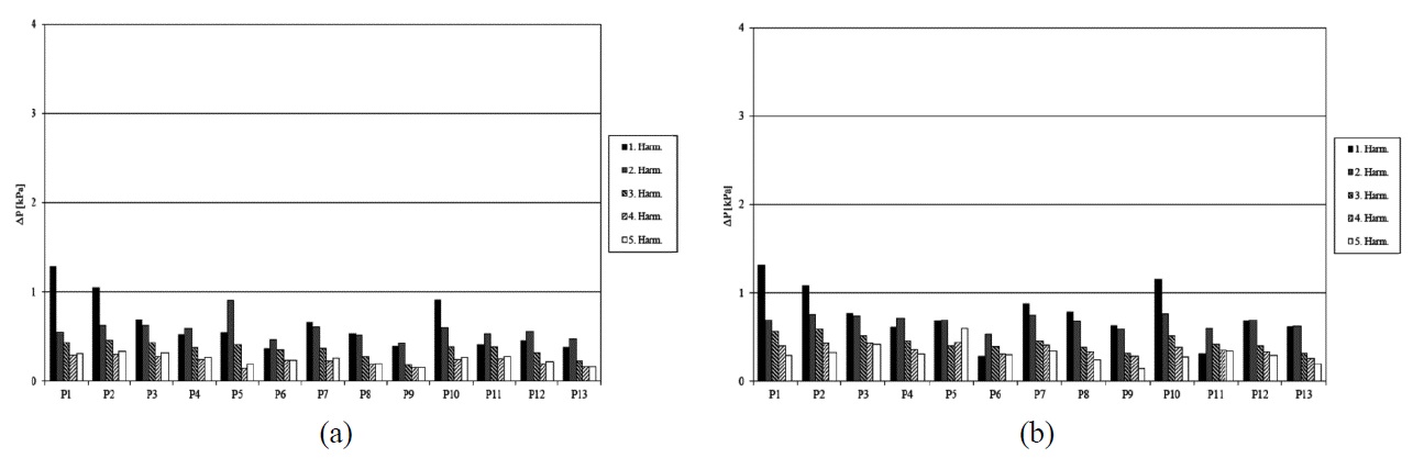
Also, hull pressure measurement was carried out at each cavitation test condition. The location and indication of the pressure pick-ups is given Fig. 20. Figs. 21 and 22 give information on the pressure signal itself at the design and ballast draft respectively; the pressure signals are compared for the bare hull and with duct condition. The harmonics of propeller blade rate order were obtained as Table 6 measured at pick-up point P1 which has shown the highest 1st harmonic amplitude in the cavitating condition.
[Table 6] Harmonics of propeller blade rate order (unit : kPa).
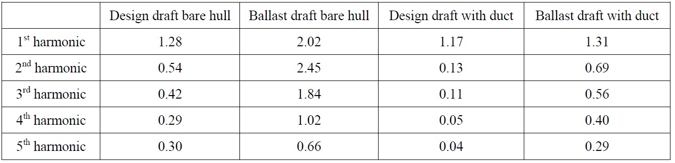
Harmonics of propeller blade rate order (unit : kPa).
The duct causes a considerable reduction of pressure amplitudes which can be clearly noticed when comparing the ‘Ballast draft with duct’, where the amplitudes turned out to be on the same level for all frequencies. The 1st harmonic remains moderate at all conditions but the 2nd and 3rd harmonics at ‘ballast draft bare Hull’ are relatively high. Thus it could cause vibration problems for the hull structure. Of course those phenomena were mainly observed at ballast draft, considering lower water line height at ballast draft, ballast pressure fluctuation by propeller cavitation could be ignored at calm sea condition in terms of ship vibration. However, the most severe design conditions should be taken into consideration in the viewpoint of design basis such as in the rough sea condition. In addition, measured hull pressure amplitudes are so closely linked to the type of cavity collapse and rebound events that cavitation phenomena could be understood best through the pressure time series and its manipulations. Consequently, harmonics of propeller blade rate order well indicate designed half circular duct control the propeller cavitation pattern and behavior effectively to be stable.
The high 2nd and 3rd harmonics registered in the ‘Ballast draft bare hull’ case cause the periodic hull pressure time function in Fig. 23 to show sudden changes from a minimum pressure level to the maximum pressure height. They are supposed to originate from abrupt changes of the cavity volume. Due to difference in the cavitation behavior from one blade passage to another, the hull pressure time signal for the cavitating propeller shows some irregularities.
Energy saving devices has been investigated meant to support the propeller performance especially on ships with large block coefficients. General options of energy saving devices are ducts and stators in front of the propeller and rudder-fins and rudder bulb mounted downstream of the propeller. In case of multiple use of the energy saving devices, compatibility investigation should be additionally carried out, because there does not remain potentially recoverable energy loss due to duplication of saving function as much as their own self-resistances.
Measuring the recovery potential in terms of power reduction at given ship speed our intention was to reach the 5% gain with the best duct arrangement. For reviewing the process of design and model testing, following basic steps were preceded on the way to the optimum solution:
(1) To study recoverable and avoidable losses arising at the propeller in open water and in a wake field.
(2) The unconventional half circular duct concept with horizontal connections to the propeller hub was selected from a variety of initial ideas
(3) Conventional circular pre-swirl duct was studied in parallel.
(4) RANS calculation was used for refinement of the pre-swirl duct concept.
(5) Unconventional half circular duct design was more refined to the measured wake and a conventional duct was considered in parallel as an alternative seemed to indicate similar benefit with a completely ring-shape device.
(6) Optimum self propulsion tests for the best configuration were carried out.
(7) Cavitation tests and hull pressure measurement for the design propeller with and without the best duct configuration of unconventional half circular duct were performed.
The unconventional circular preswirl duct has been initiated from a variety of duct ideas. The unconventional duct has 3 basic parts, namely a larger upper semi-circle part, a nearly horizontal part and vertical stator fin inside duct, which was selected and has been refined by further investigation.
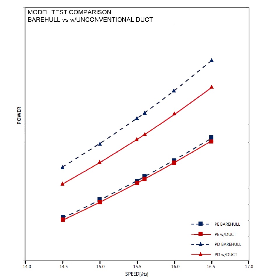
The upper/lower-asymmetry of the bare hull wake at the propeller disk is homogenized by the half circular duct installed in front of the propeller plane. Also, the straightening of the cross flow obtained is a positive side effect of the duct. Going through a design and analysis phase, about 5.4% power saving effect is achieved at whole range of ship speeds and confirmed by the model test (Fig. 24).
Also a duct of conventional shape was studied together. The conventional circular pre-swirl duct showed similar performance (slightly less than to the unconventional half circular duct) in towing tank test.
Finally the unconventional half circular duct has been decided and entered to the cavitation tests. The blade surface and tip vortex cavitation behaved smoother when the duct was mounted. The hull pressure amplitudes reflect these differences as especially the pressure amplitudes related to the higher harmonics were smaller with duct than without duct condition.
Meanwhile if energy saving devices is applied to the full scale vessel, some taking in consideration of design modification would be necessary due to the different situation of full scale that will change the wake characteristics. The recovery potential from the duct due to the acceleration of locally retarded flow will be reduced in full scale. The crosses components from the bilge vortex seem to be still modified positively by the duct in full scale. So, the benefits of the bilge vortex development supperssion function could show almost same level between in model or full scale. Furthermore, the pre-swirl generation effect of the unconventional circular duct and related recovery of rotational energy would be expected same. However, the geometry of preswirl duct such as a duct angle or the pitch angle of horizontal and vertical stators should be slightly modified according to the full scale wake. Therefore, additional full scale CFD calculation should be needed for application to full scale vessel.