Underwater acoustic networks (UANets) have opened new research opportunities and promise great potential for underwater exploration, resource monitoring, and military applications [1]. Simultaneously, we have faced remarkable limitations of UANets compared with terrestrial wireless networks (TWNets), including narrow bandwidth, a low data rate, and a large propagation delay [2-4]. Under these restricted network environments, a medium access control (MAC) protocol can play a crucial role in enhancing overall performance by efficiently sharing limited network resources and avoiding collisions among underwater nodes (UNs) [5]. A large volume of literature on MAC protocols for UANets has been produced [6,7]. Designing a proper MAC protocol for a UANet executing a target application is still in progress [8,9].
Without loss of generality, a MAC protocol for UANets is required to mitigate their aforementioned intrinsic restrictions. It is remarkable that the propagation delay of acoustic waves in underwater is five orders of magnitude higher than that of radio waves in the air [10]. The transmission delay underwater is also higher than that in the air due to the slow data rate of underwater acoustic channels [11]. Under these fixed delays determined by the physical layer, a MAC protocol is required to reduce overall end-to-end delay by efficiently managing the channel access of UNs.
It is also necessary for a MAC protocol to consider the characteristics of UANet applications. There are a variety of UANet applications, such as scientific monitoring or surveillance underwater [12]. These UANet applications are mostly on-demand, which implies that UNs are deployed and requested to work only once demand arises. In these UANet applications, UNs (e.g., autonomous underwater vehicles [AUVs], acoustic sensor motes, and submarines) move around underwater at different speeds. Accordingly, a MAC protocol needs to manage various on-demand UANet applications, as well as consider UNs’ mobility.
The overall topology is another consideration upon designing a MAC protocol. In practice, the data obtained from several UANet applications are mainly sent to a terrestrial base station, which can be connected to IP-based backbone networks. Namely, from a network perspective, the overall data from UNs to a terrestrial base station are passed through a hierarchical network architecture consisting of a TWNet and a UANet. In a TWNet, multiple surface stations, which gather data from several UNs and forward the data to a terrestrial base station, are deployed on the water’s surface. A UANet is composed of several clusters. The communication range of a cluster is determined as the one-hop transmission distance between a surface station and UNs [13,14]. Under this hierarchical network structure, multiple access of surface stations can be mutually related to that of UNs since important information (i.e., UNs’ mobility information and the number of UNs in a cluster) can directly affect the ingress traffic load flown into each surface station. Accordingly, it is expected that a hybrid MAC protocol considering this hierarchical network structure could be more appropriate than two separate MAC protocols, respectively, corresponding to the two networks.
In the literature, several hybrid MAC protocols have been proposed for hierarchical networks. Commonly in the literature, MAC protocols among surface stations are confined to time division multiple access (TDMA), but those among UNs vary, and include TDMA, code division multiple access (CDMA), and even a contention-based MAC protocol. In [14], a MAC protocol consisting of TDMA and CDMA does not consider the mobility of UNs such that idle time slots may occur when the UNs move around from cluster to cluster. In [12], the MAC protocol consists of TDMA and a distributed coordination function. Although the MAC protocol allocates a fixed number of time slots into UNs according to the mobility of the UNs, several UNs that are not allowed to use a time slot are still idle, which increases the overall delay. In [15], another MAC protocol consists of two TDMA scheduling, where a portion of the UNs are only pre-allocated to use the time slots without considering the mobility of UNs, such that the remaining UNs are still idle.
In this paper, we propose a new MAC protocol, referred to as hierarchical time division multiple access (HTDMA). Although TDMA may not suit a UNs’ mobility because of the high setup cost and difficulty of frequent schedule changes, HTDMA is based on TDMA because of the advantages of TDMA, including its simplicity, collision-free nature, energy-efficiency, and lack of control signaling [12]. To consider frequent changes in the mobility information of UNs, we make surface stations share the mobility information in a round-robin manner and broadcast the information to their UNs. Thus, HTDMA can satisfy the above considerations and utilizes the mobility of UNs to reduce the overall delay. HTDMA is a hybrid MAC protocol consisting of two TDMA scheduling; TDMA1 for a TWNet and TDMA2 for a UANet. TDMA1 periodically pre-assigns all of the surface stations to a fixed time slot as normal TDMA does. Each surface station forwards data received from diverse UANet applications to a terrestrial base station, and it also broadcasts mobility information of UNs to other surface stations in its pre-allocated time slot. Although contention-based MAC protocols can also be good candidates, TDMA1 is considered for a TWNet due to the advantages of TDMA, as explained earlier. TDMA2 is ondemand; several TDMA2s can be concurrently executed under TDMA1 with respect to ongoing applications. In one application, TDMA2 is implemented in each cluster, respectively, and the corresponding time slot allocation is instantaneously determined by the mobility information of the UNs provided by the surface station. By doing this, HTDMA can overcome the intrinsic limitations of TDMA such as its weakness in dealing with mobility and the occurrence of idle time slots. Accordingly, it is expected that HTDMA may reduce end-to-end delay, as well as improve channel utilization by accommodating various UANet applications.
This paper is structured as follows. We outline previous works on MAC protocols targeted for UANets in Section II. A UANet topology is described in Section III. In Section IV, we detail HTDMA. In Section V, the delay of HTDMA is analytically investigated and compared with those of TDMA and Slotted-ALOHA. Finally, we conclude this paper in Section VI.
II. PREVIOUS WORKS ON MAC PROTOCOLS FOR UANETS
In this section, we give a brief summary of previous works on MAC protocols designed for UANets. These MAC protocols are broadly categorized into two types: contention-based and contention-free MAC protocols [13]. Contention-free MAC protocols can be advantageous over contention-based MAC protocols in that they can avoid the
message overhead in protocols such as request-to-send and clear-to-send handshaking of carrier sense multiple access (CSMA) or multiple access with collision avoidance (MACA) [16]. In addition, contention-free MAC protocols are delay-tolerant while contention-based MAC protocols such as ALOHA or Slotted-ALOHA result in severe delays in heavy traffic-loaded environments [17]. Even CSMA and MACA may result in significant random back-off delay when the overall network traffic load increases. Contentionbased MAC protocols also induce the hidden- or exposedterminal problem.
TDMA, frequency division multiple access (FDMA), and CDMA are contention-free MAC protocols. Among them, FDMA is considered inefficient for UANets due to the lack of acoustic frequencies that originate from limited bandwidth of the acoustic channel [18]. CDMA can reduce contention and has other benefits for UANets. CDMA requires code assignment and a power control algorithm in order to reduce contention among UNs and a near-far problem. This results in high hardware complexity, decreasing already limited data rates, and thus wasting more energy [1,17]. TDMA, a simple schedule-based approach with a single frequency, can save energy by allowing UNs to turn on their systems only during scheduled time slots without wasting energy due to idle listening and collision [15]. TDMA has recently attracted significant attention for many UANet applications [19-21]. In spite of its advantages, TDMA is still weak in dealing with the mobility of UNs, which is a significant requirement of current UANet applications [13].
TDMA is also extended to a hybrid MAC protocol in order to be suitable for a clustered network topology. The proposed hybrid MAC protocols commonly consist of an intra-cluster MAC protocol and an inter-cluster one. An intra-cluster MAC protocol corresponds to multiple access of several UNs in a cluster. An inter-cluster MAC protocol manages multiple access of several surface stations. Commonly in the literature, the intra-cluster MAC protocol is confined to TDMA, but inter-cluster MAC protocols have included TDMA, CDMA, and even a contention-based MAC protocol. In [14], the authors propose a MAC protocol consisting of TDMA and CDMA. Each cluster with a specific code supports a fixed number of time slots using TDMA. The authors focus on assigning a limited number of codes without overlapping in an inter-cluster MAC protocol. However, this MAC protocol consequently does not consider the mobility of UNs, such that idle time slots may occur when UNs move around from cluster to cluster. In [12], the authors propose a MAC protocol that consists of TDMA and a distributed coordination function. According to the network topology and mobility of UNs, they allocate a fixed number of time slots to the UNs and surface stations in TDMA. Although they can minimize the number of idle time slots, some UNs, not allowed to use a time slot, can still become idle such that the overall delay may increase. In [15], a MAC protocol combining two TDMA scheduling is introduced. As in [12], a portion of the UNs are only preallocated to use the time slots without considering the mobility of the UNs, which is statistically determined such that the remaining UNs are still idle.
[Table 1.] Network parameter descriptions
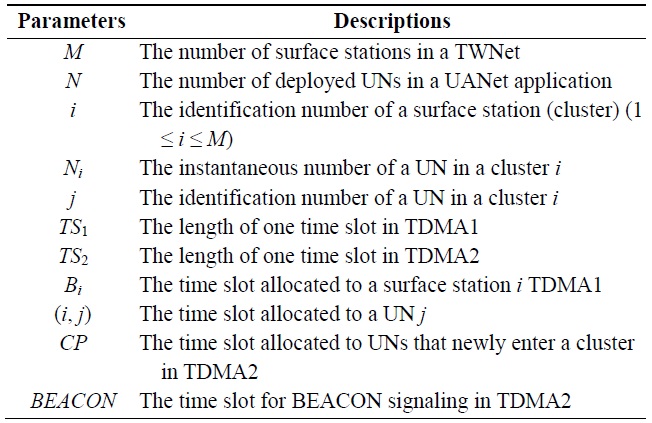
Network parameter descriptions
III. NETWORK ARCHITECTURE DESCRIPTION FOR UANET APPLICATIONS
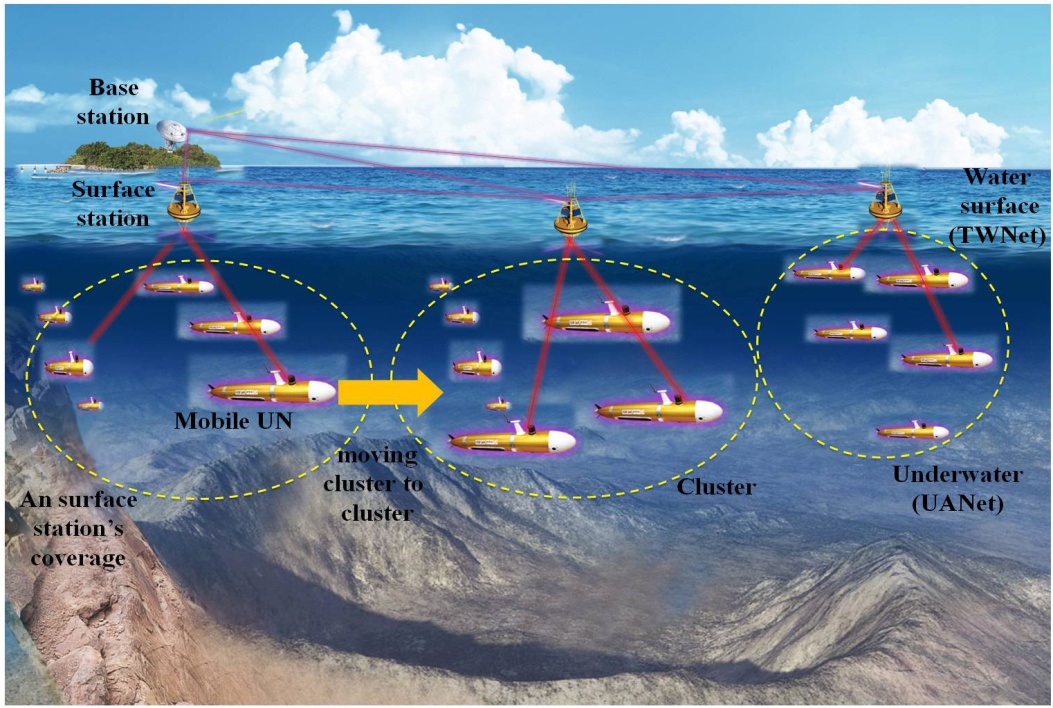
In this section, we describe an overall network topology executing several applications for UANets concurrently. Target applications can be specified as on-demand applications for the short-term and wide-area exploration and detection. The practical use of such applications is exemplified by underwater detection using mobile UNs like AUVs, cooperative tasks using mobile UNs like underwater robots in a wide area, underwater exploration (e.g., oil fields or reservoirs), assisted navigation (e.g., identifying hazards or submerged wrecks on the seabed), or mine reconnaissance [22]. As illustrated in Fig. 1, the network consists of two sub-networks, including a TWNet and a UANet.
In the TWNet, several surface stations are deployed on the surface of the water. A surface station has a significant role: connecting the UNs to a terrestrial base station. To do this, a surface station has two communication modes (i.e., terrestrial wireless communication and underwater acoustic communication). That is, a surface station gathers data sent by UNs currently residing in its communication territory using underwater acoustic communication, and also stores the data in its buffer, converting the data into a proper packet format, and forwards the data to a terrestrial base station using terrestrial wireless communication. In addition, a terrestrial base station can send control packets to all surface stations by using a different RF frequency, which informs them of the installation of a new UANet application. Like the UNs, when surface stations experience channel contention with other surface stations medium access among surface stations is also considered in the data-link layer.
A UANet contains multiple clusters, which are respectively governed by a corresponding surface station. Once a specific UANet application is requested, multiple UNs, which are equipped with the same communication systems and sensors, are deployed in an overall UANet: each cluster momentarily has several UNs. As the moving distance can be longer than the communication range of a surface station, the deployed UNs move from one cluster to another: the moving speed of AUVs is around a few meters per second. In addition, the distance between the clusters is less than one hundred meters. When a UN is released, it tries to determine the nearest cluster by sensing the signaling power of a surface station (e.g., BEACON packet). After the UN receives the BEACON packet, it tries to register with the surface station via authentication and then send data, if permitted. When the UN enters a new communication territory of another surface station, its channel access and data transmission is instantaneously managed by a new surface station. As far as mobility is concerned, the mobility information of the UN may be shared among all of the surface stations via handover among surface stations. These activities are totally dependent on HTDMA, a MAC protocol presently in use, which are explained in Section IV.
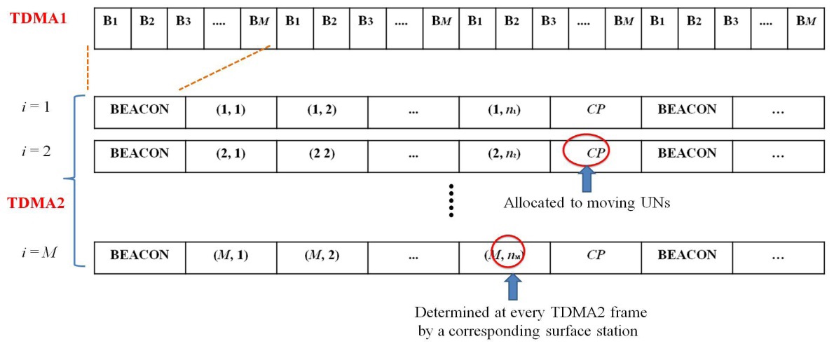
HTDMA consists of scheduling of two TDMA protocols: TDMA1 and TDMA2. TDMA1 is constantly executed among surface stations, but TDMA2 is executed when a specific UANet application is requested. In TDMA1, a surface station gathers data from UNs currently residing in its cluster. The surface station delivers the data to a terrestrial base station in its assigned time slot in TDMA1. The surface station also obtains the mobility information of a UN which is currently in its cluster and send its mobility schedule (i.e., leave or stay in a current cluster). After receiving the mobility information of all of the UNs belonging to its cluster, the surface station shares the mobility information with other surface stations in TDMA1. Collecting mobility information between a surface station and a UN and sharing the information among surface stations can be costly. As a UN sends data and mobility information to a surface station at the same time, the size of the packets can increase. Similarly, the size of a surface station’s packets can also increase. At the expense of the mobility information, surface stations can determine the frame size of TDMA2 on the basis of the mobility information in TDMA1. In TDMA2, a surface station assigns time slots to UNs that are currently in its cluster by broadcasting a BEACON packet at the start of one TDMA2 frame. Although a UN may take energy by listening to BEACON packets, its battery can be recharged when they return. Thus, we do not consider energy-efficiency upon
designing HTDMA. The UNs transmit data packets to their surface station in its pre-allocated time slot. We define the network parameters as shown in Table 1 and consider the following premises upon employing HTDMA.
1) Due to remarkably longer propagation and transmission delays in the acoustic channel, the length of one TDMA2 time slot (TS2) can be much longer than that of one TDMA1 time slot (TS1). We determine TS2 as M × TS1. The case of M = 1 (i.e., only one surface station in one cluster) is not considered because a surface station should exchange the mobility information of its UNs with other surface stations.
2) TS2 is only used toward a UN for a UANet application. TS1 is also employed toward a surface station but for multiple on-going UANet applications.
3) TS2 consists of the maximum propagation delay in a cluster, transmission delay, and guard time required for time synchronization.
4) The length of the BEACON time slot and that of the time slot pre-allocated to a UN is assumed to be equivalent for simplicity. However, the contention period (CP) time slot reserved for new UNs should be flexible according to the mobility of the UNs. If the mobility is high, the length of the CP time slot should increase.
5) As HTDMA is a TDMA-based MAC protocol, time synchronization is strongly required to synchronize the start and end time points for a time slot underwater. We assume that HTDMA is executed by accompanying a proper time synchronization method such as [23,24].
Specifically, TDMA2 is initiated, operated, and terminated through three stages; the initialization, normal operation, and termination stages. In the initialization stage, each surface station determines the number of time slots assigned to UNs initially residing in its communication territory once TDMA2 is requested as a response to a new UANet application. In the normal operation stage, a mobile UN sends data packets to a current surface station. The frame size of TDMA2 varies according to the overall mobility pattern of the UNs. The termination stage is requested by a surface station or a terrestrial base station when an on-going UANet application ends. Below, we further detail HTDMA according to three stages.
The initialization stage basically starts when a specific UANet application is requested. The initialization stage is executed step by step as follows.
1) A terrestrial base station preliminarily sends several pieces of information, including the number of deployed UNs (N) and UNs’ MAC addresses, and initial identification numbers (i.e., 1 to N) to all surface stations when a new UANet application is ready.
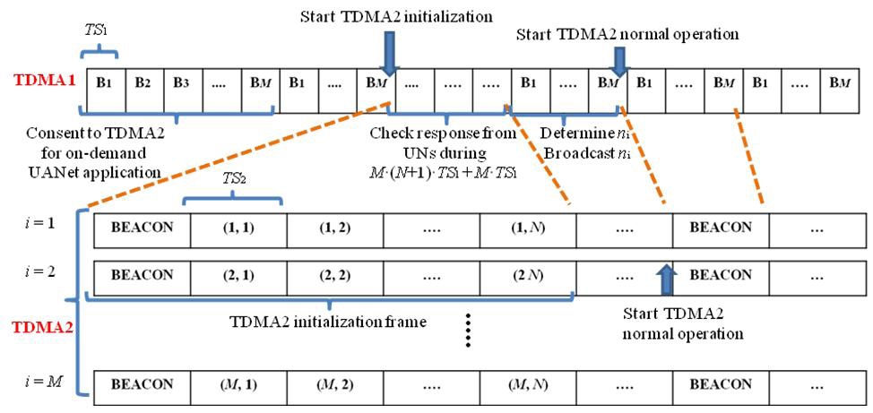
2) Each surface station consents to start TDMA2 targeted for a requested application during one TDMA1 frame, as shown in Fig. 2.
3) At the time point after one more TDMA1 frame passes, the TDMA2 initialization frame starts, which consists of one BEACON time slot and N time slots, as illustrated in Fig. 2. In the BEACON time slot, a surface station sends time slot allocation information to multiple UNs in its cluster. Then, those UNs inform the surface station of their presence in their pre-assigned time slot, respectively. Each surface station takes as
much as M × (N + 1) × TS1 + M × TS1 to executed the TDMA2 initialization, where TS2 = M × TS1. During this TDMA2 initialization frame, a surface station receives presence information on its UNs and also continuously broadcasts this information to other surface stations via its TDMA1 time slot.
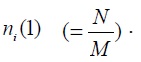
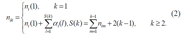
4) After the TDMA2 initialization frame, a surface station i determines the number of time slots of TDMA2, ni, corresponding to UNs presently residing in its cluster. Then, the surface station broadcasts ni information to the other surface stations.
5) When all of the surface stations have broadcast ni information, they each send a BEACON packet to their respective UNs in a UANet using TDMA2. This is the start of TDMA2 targeted for a specific UANet application.
6) Even during an on-going UANet application, the initialization stage is also requested by a surface station when it detects the failure of time synchronization.
The normal operation stage continues until an ongoing UANet application is terminated. A surface station maintains the mobility status of UNs presently located in its cluster and shares the information with other surface stations using TDMA1. When TDMA2 starts, a surface station
By receiving the
A UN can know whether it enters a new cluster by receiving a
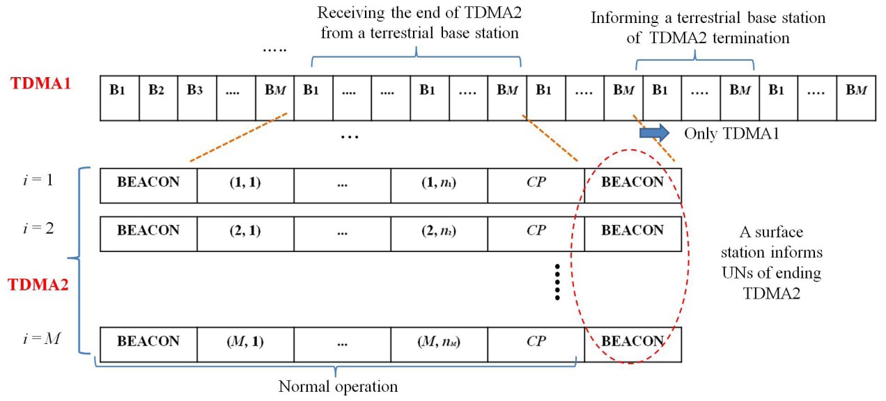
The termination stage occurs when an ongoing UANet application ends. The termination stage is also executed as follows.
1) A terrestrial base station informs all surface stations of stopping a pending UANet application.
2) After an ongoing TDMA2 frame corresponding to the application is over, a surface station sends a BEACON packet to its UNs, implying the end of TDMA2, as illustrated in Fig. 4.
3) When a UN receives the BEACON packet, it stops sending data packets any longer and prepares to return.
4) The surface station informs the other surface stations of the end of TDMA2 targeted for the ongoing UANet application.
5) When all of the surface stations have broadcasted their TDMA2 termination, they inform the terrestrial base station of the termination in their TDMA1 time slot.
In the termination stage, more than one UANet application can be finished by following the above termination procedures.
V. PERFORMANCE ANALYSIS OF HTDMA MAC PROTOCOL
Decreasing the delay for UANets has been a crucial issue in the literature because the propagation delay of acoustic signals is five orders of magnitude higher than that of RF signals [25-28]. In this section, we analytically investigate the delay of HTDMA. We also derive the delays of TDMA and Slotted-ALOHA and compare them with that of HTDMA. Before the derivation of delay, the mobility of a UN is primarily modeled, as illustrated in the following subsection.
Let us denote
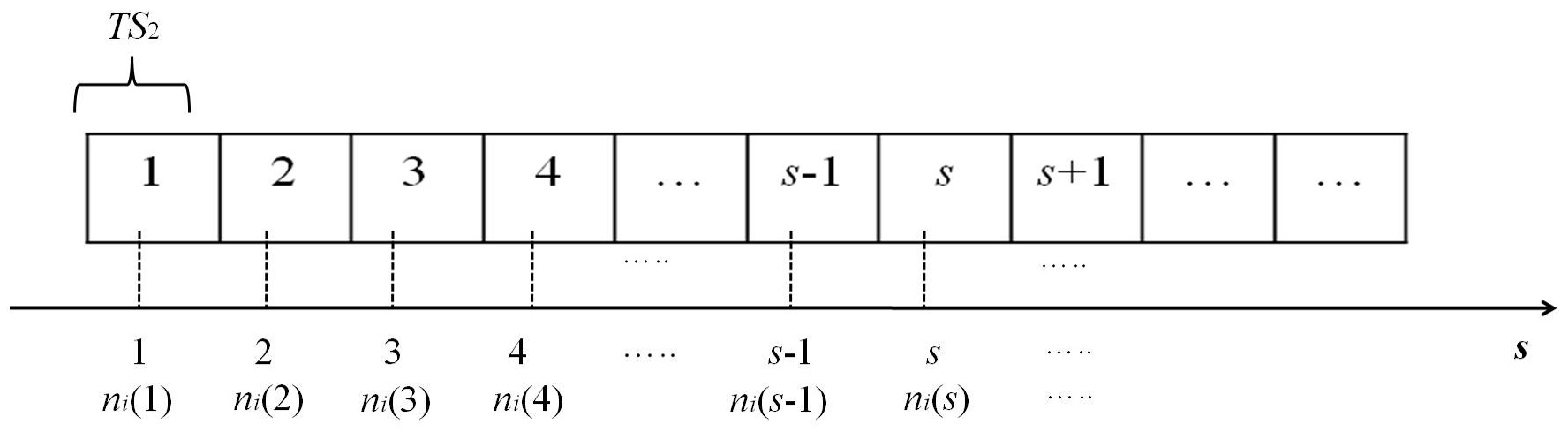
At an arbitrary TDMA2 time slot s in a cluster
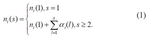
When a UN moves from one cluster to another, it cannot receive any
>
B. Delay Parameter Derivation
1) The delay of HTDMA
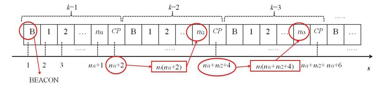
Let us denote the TDMA2 frame index as
Initially,
As illustrated in Fig. 5,
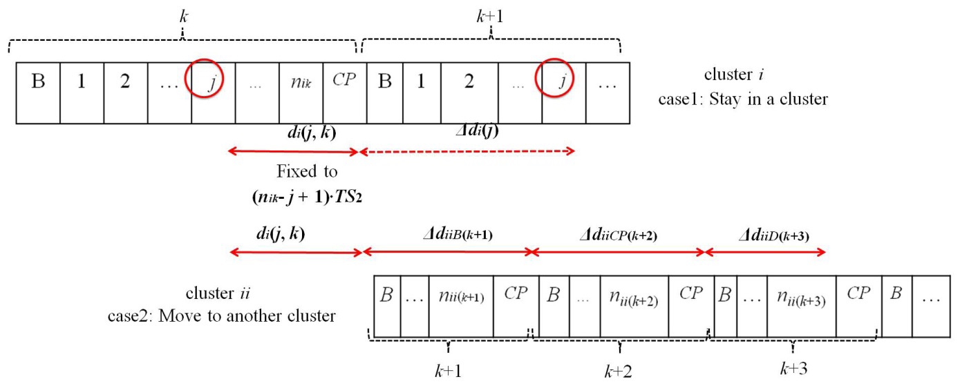
The delay is defined as the time in which a UN waits for its next allocated time slot in the TDMA2 frame and sends data packets. We consider a UN in a cluster
First,
As shown in Fig. 6,
where

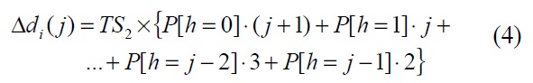
Δ
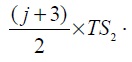
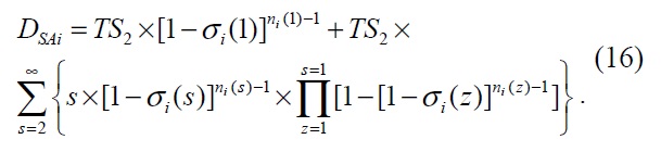
Accordingly, the average delay of a UN in a cluster
where
similarly defined. If we assume that

and
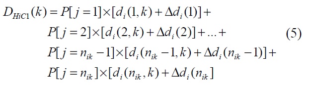
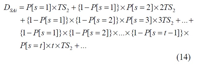
Second,
where Δ
As illustrated in Fig. 6, we can obtain Δ

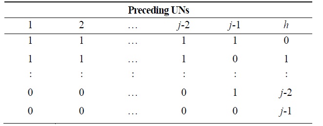
[Table 2.] h values according to the mobility status of preceding underwater nodes (UNs)

h values according to the mobility status of preceding underwater nodes (UNs)


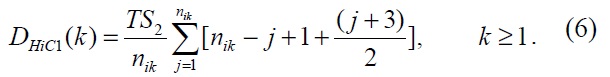
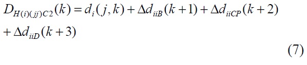
By substituting Eqs. (8)?(10) into Eq. (7),
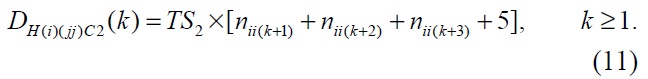
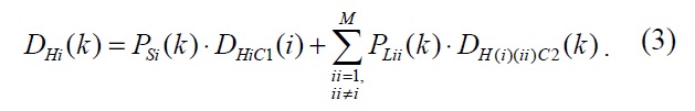
By substituting Eqs. (6) and (11) into Eq. (3) and assuming that
at simplicity,
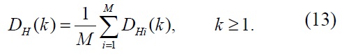
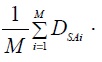
Finally, the average delay of all surface stations at the
2) The delay of TDMA
In case of TDMA, each surface station just preallocates a fixed number of time slots regardless of the mobility of UNs. Thus, a TDMA frame consists of
3) The delay of Slotted-ALOHA
Slotted-ALOHA is similar to HTDMA in that the data packet transmission of UNs is executed during one time slot. We consider that the length of a time slot in Slotted- ALOHA is the same as
where
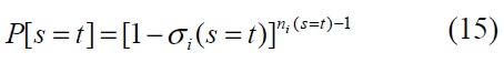
and Eq. (8) implies that
Similarly, the average delay of all of the surface stations employing Slotted-ALOHA,
We analytically investigated the delay of HTDMA by using derived delay equations under the following conditions.
1) The diameter of a cluster governed by a surface station is given as 1,500 m with an acoustic velocity of 1,500 m/s as exemplified in [13]. Thus, the maximum propagation delay is determined to be 1 second. In addition, [13] considers the data rate of 300 bps with a packet length of 32 bytes such that the transmission delay is obtained as 0.85 second. As defined, TS2 consists of a propagation delay, transmission delay, and some guard time for time synchronization. Finally, we fix TS2 to 2 seconds with a guard time of 0.15 second.
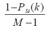
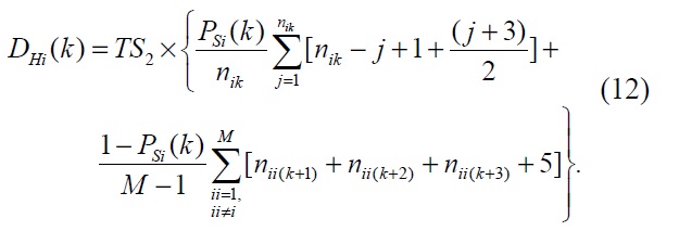
2) We model the mobility of UNs by defining the degree of mobility, mp (1≤ mp ≤ 10). It is modeled such that the number of egress and ingress UNs per time slot s depends on the value of mp, which determines the probability that a UN stays in a cluster i during the frame k, PSi (k) =1? 0.1×mp . For example, mp = 1 implies a UN may stay in a cluster with a probability of 0.9. Namely, the higher mp is, the greater possibility that a UN moves to another cluster.
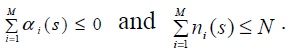
3) We consider σi(s) to be the normalized traffic load flown into a UN at a surface station i at TDMA2 time slot s assuming that the traffic load to all UNs in a cluster is equivalent at simplicity. σi(s) is considered in the range of 0.1 to 0.9 for numerical analysis.
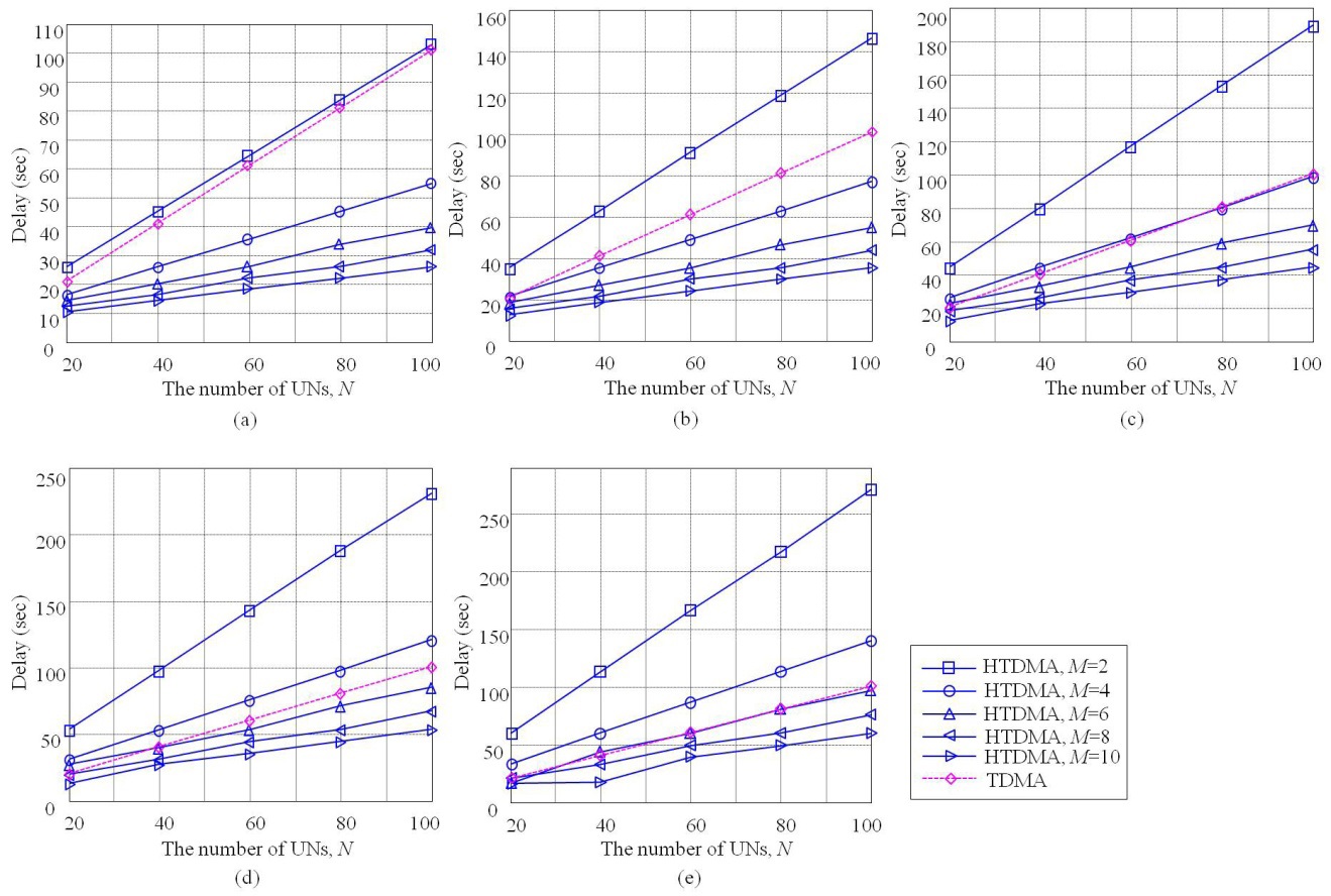
4) M varies from 2 to 10 and N varies from 10 to 100 in order to investigate the effect of M and N on the delay performance.
Under these conditions, we compare the delay of HTDMA with that of TDMA. Fig. 8 illustrates the delays of HTDMA and TDMA according to
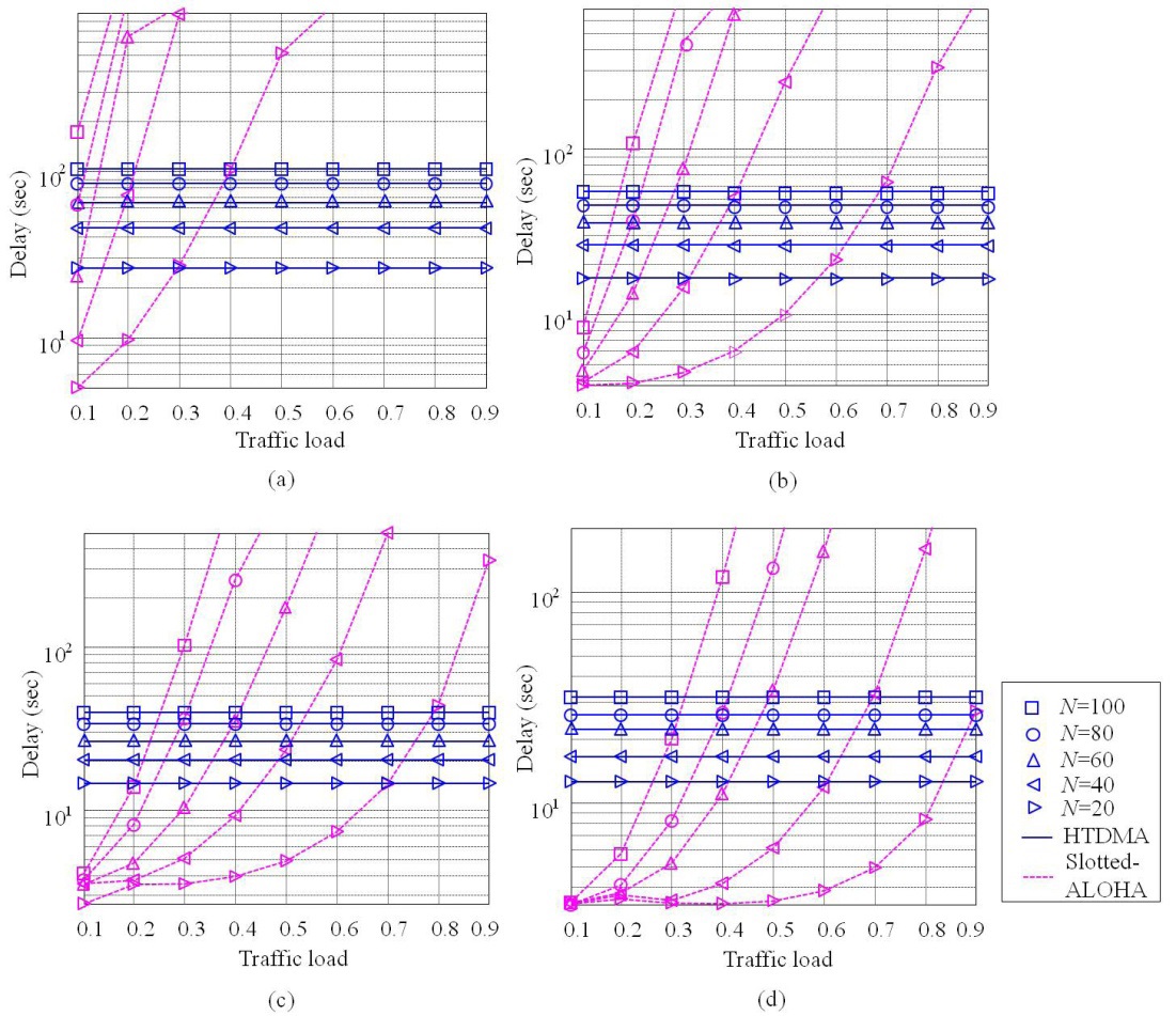
We also compare the delay of HTDMA with that of Slotted-ALOHA. As illustrated in Fig. 9, the delay of Slotted-ALOHA also decreases as
increase, Slotted-ALOHA results in unbounded delay, while HTDMA supports a consistent delay regardless of traffic loads by pre-assigning a time slot for a specific UN. In addition, the delay of Slotted-ALOHA increases as
VI. DISCUSSION AND CONCLUSIONS
In this paper, we propose a new MAC protocol, referred to as HTDMA, which is composed of TDMA1 and TDMA2. A major function of TDMA1 is to cover diverse on-demand UANet applications and forward data from these appli-cations to a terrestrial base station. TDMA2 is separately executed in all clusters once a specific application is requested. The number of time slots in each cluster is managed by all of the surface stations, which shares mobility information using TDMA1. Then, each surface station allocates time slots into UNs currently residing in its cluster using TDMA2. With the help of HTDMA, we can accommodate multiple UANet applications simultaneously, and also improve delay performance by efficiently controlling the mobility of UNs. It has been analytically shown that HTDMA can reduce the delay of TDMA, particularly in the case that the number of clusters increases. In addition, HTDMA can outperform Slotted-ALOHA in terms of delay in the case of severe contention environments such as heavily loaded traffic under an increase in the number of UNs in a cluster. This implies that HTDMA can reduce the possibility of dropped data in the queue or lost data in the channel by decreasing the overall network delay. Furthermore, HTDMA is expected to improve channel efficiency by avoiding the occurrence of idle time slots induced by UNs’ mobility. Numerical results can be displayed in an engineering table, which should be helpful for designing a UANet. Finally, delay analysis considering mobility modeling could be employed in other MAC protocols for a UANet such as pure ALOHA and extended to other network scenarios.