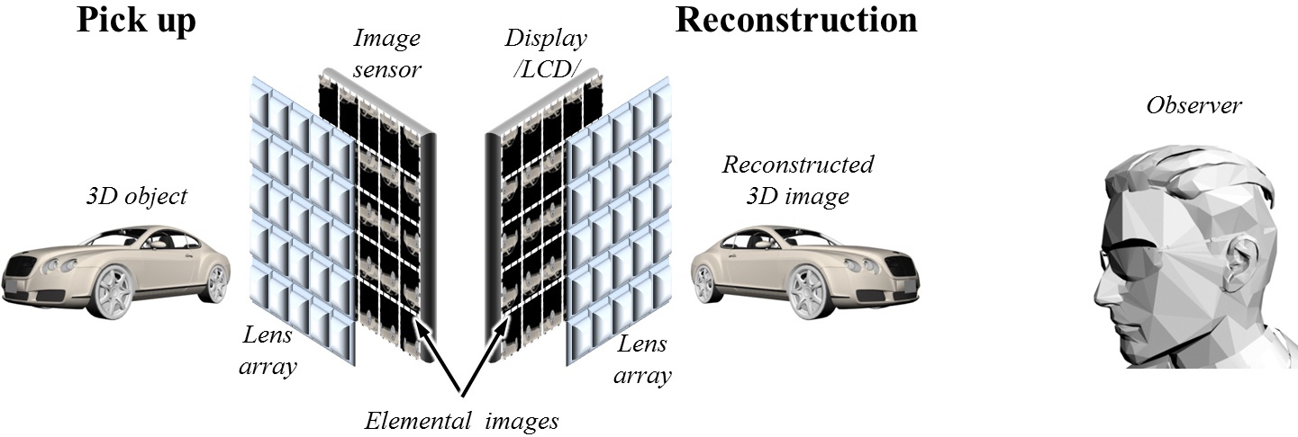
Integral imaging is a distinguished technique among various three-dimensional (3D) display methods. It has two main parts: pick-up and reconstruction as shown in Fig. 1. In the pick-up part, the light coming from 3D
objects passes through a lens array, being recorded at the sensor plane as a set of elemental images. The elemental images include different perspectives’ information of the captured 3D object. In the reconstruction part, a full-parallax 3D image can be displayed in real-time with different perspectives according to viewing direction from a recorded set of elemental images by using the same lens array. However, reconstructed 3D images have narrow viewing angles limited by the numerical aperture of each lens in the lens array [1-5].
Some research has been conducted in order to solve the narrow viewing angle problem [6-8]. Shifting a dynamic barrier array which is allocated between display device and lens array [6], or moving a lens array [7-8] in synchronization with the display device can improve the viewing angle of the integrated 3D images. However, those methods require two-dimensional (2D) scanning movement of the lens array or barrier array, and hence they are not easy to implement in real-time. Viewing angle enhancement methods without mechanical movement, such as using a double display device and time multiplexing [9], embossed screen [10], curved lens array and curved screen [11-12], double collimated illumination [13] and negative index plano-concave lens array [14] have also been reported. Those methods, however, do not provide a viewing angle wide enough for a comfortable viewing experience.
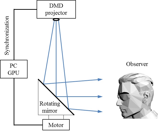
Recently, a rotating-mirror-screen type volumetric light field display that projects 2D images to corresponding directions has been reported, demonstrating a 360 degree horizontal viewing angle which means displayed 3D image can be observed from any horizontal direction around the display system [15-17]. In an implementation, a high frame rate digital micro-mirror device (DMD) projects 288 different perspectives per round when the mirror screen rotates more than 900 rounds per minute (rpm) as shown in Fig. 2. Main advantage of this system is that it can present 360 degree horizontal viewing angle 3D images, enabling walk-around viewing. However, the presented 3D images have only horizontal parallax and a viewer tracking system is required for vertical parallax.
Also the angular light ray sampling rate is given by the angular step of the rotating mirror which is limited by the frame rate of the projector. In order to present 3D images with angular light ray sampling rate high enough for correct accommodative response of the observer, the projector needs to operate at a very high speed, which can impose a problem in practical implementation.
Full-parallax omni-directional 3D display by combining integral imaging display with the rotating mirror screen configuration has been reported by D. Miyazaki et al.[18] and M.-U. Erdenebat et al.[19] In D. Miyazaki et al.’s work, however, experimental demonstration is not presented. M.-U. Erdenebat et al.’s work suffers from flipped images that degrade the final image quality.
In this paper, we report a new implementation of the full-parallax omni-directional 3D display by combining integral imaging display with the rotating mirror screen configuration. The proposed system can provide 3D images over 360 degree horizontal angle, overcoming the narrow viewing angle of the conventional integral imaging display. Full-parallax images are presented with a higher angular light ray sampling rate than conventional rotating screen light field display and without using any tracking system. Unlike previous works by D. Miyazaki et al. and M.-U. Erdenebat et al., the proposed system tailors the viewing angle of the relayed 3D images to match the angular step of the rotating mirror and uses a collimated elemental image projection to remove repeated 3D images in integral imaging display. In the following sections, we present the system design with an experimental result.
II. PROPOSED SYSTEM WITH 360 DEGREE HORIZONTAL VIEWING ANGLE
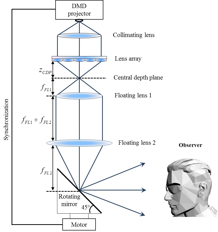
Figure 3 shows schematic configuration of the proposed method. For a given mirror angle, the corresponding elemental images are projected by a DMD projector to a lens array through a collimating lens. The lens array integrates the elemental images into a 3D image. The reconstructed 3D image is then relayed by a double floating lens system to the mirror space. Finally, the mirror directs the relayed 3D image to a specific direction. The DMD projector and the rotating mirror operate in synchronization such that proper 3D images can be projected to the corresponding directions.
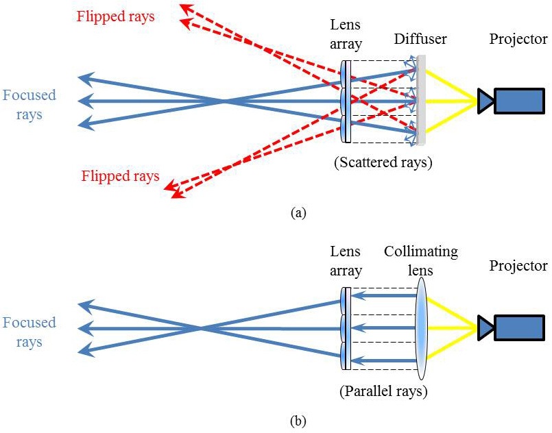
In usual integral imaging display, the elemental images are displayed on a flat panel display or projected on a diffuser screen, which causes repeated 3D images in the imaging space [2]. These repeated images can be relayed to the rotating mirror screen and seen at the same time when the integral imaging is combined with the rotating mirror configuration [19]. In our system, a collimating lens is used instead of the diffuser screen, making only a correct single 3D image to be relayed to the rotating
mirror screen and observed [13]. Figure 4 illustrates the difference between the diffusive screen case and the collimating lens case.
In the proposed method, the double floating lens system which has a 4-
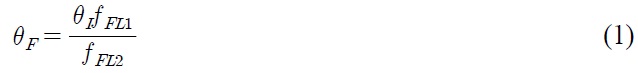
where
Note that the combination of the integral imaging display and the rotating mirror screen configuration with a viewing angle matching can enhance the angular light ray sampling rate over conventional rotating screen light field display at a given projector speed. In conventional rotating mirror screen light field display which projects a 2D image to the rotating mirror, the angular spacing between the reconstructed light rays is given by the angular step of the rotating mirror. In the proposed system, however, the angular spacing between light rays is given by
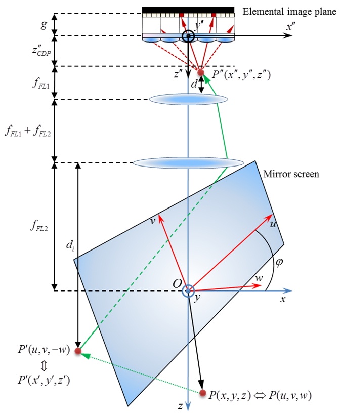
In the proposed method, the elemental images are calculated considering the angle of the rotating mirror. As shown in Fig. 5, let us define three coordinate systems (
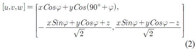
where
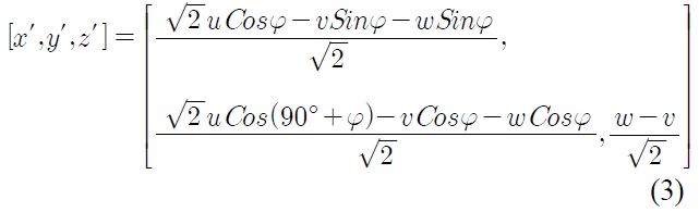
Finally,
corresponds to a point
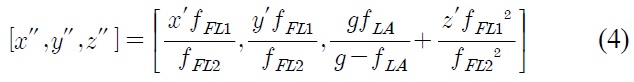
where
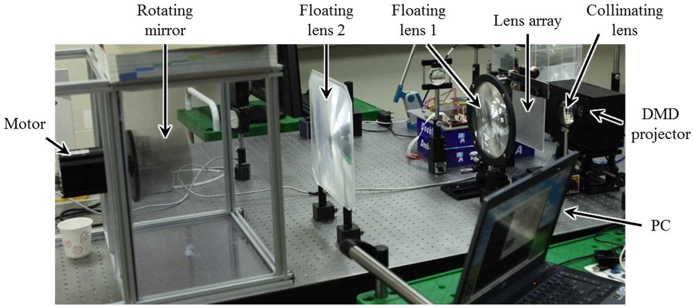
Figure 6 shows the experimental setup. We used a collimating lens with 85 mm focal length, a high-speed DMD projector with 1024×768 resolution, a lens array with 150×150 elemental lenses of 1×1 mm lens pitch and 3.3 mm focal length. The double floating lens system consists of two Fresnel lenses with 110 mm and 318 mm focal lengths, respectively. For a rotating mirror system, a flat mirror of 100×150 mm2 size and a motor are used. The motor is synchronized to the DMD projector so that a different image can be projected in every 1.8 degrees on the rotating mirror. Note that in our experimental setup the whole system was laid on the optical table for easier implementation. Also note that the viewing angle of initial 3D images integrated by the lens array is about 12 degrees. After the double floating lens, it is reduced to 4 degrees along horizontal and vertical directions. We chose 4 degree viewing angle to reduce overlapping between the angular projections while keeping vertical parallax visible.
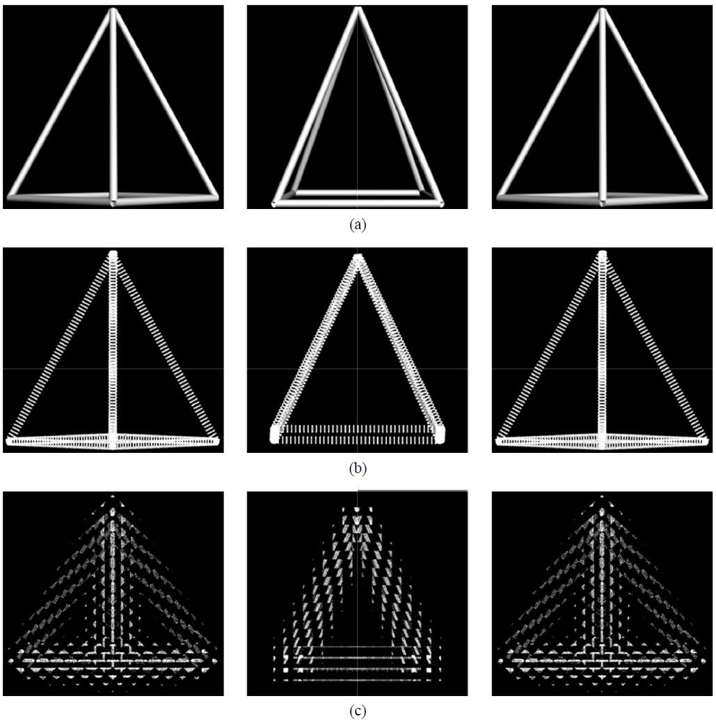
The object used in the experiment is a virtual 3D skeleton of a pyramid as shown in Fig. 7(a), and Fig. 7(b) shows the point cloud representation of the object.
For each object point, the elemental image points are calculated considering azimuthal angle of the rotating mirror and the double floating lens as explained in a previous section and these elemental image points for every object point are aggregated to generate final elemental images. Three examples of the generated elemental images are shown in Fig. 7(c).
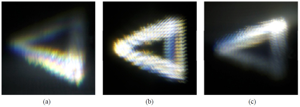
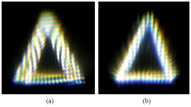
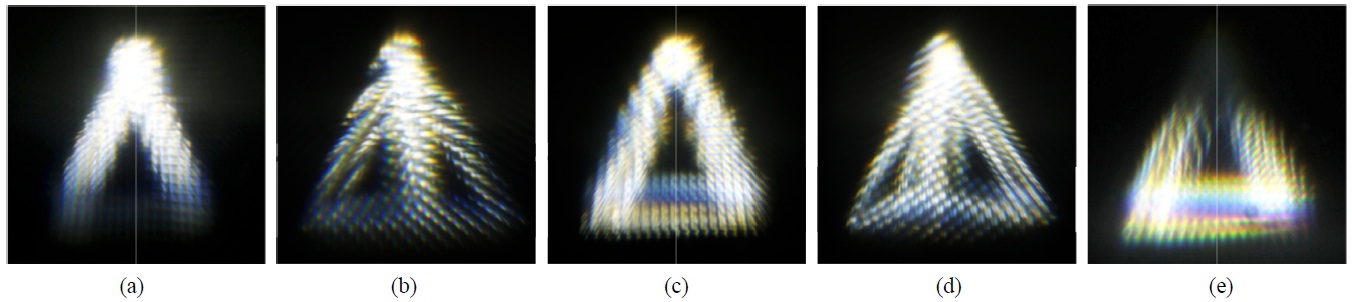
The experimental result is shown in Fig. 8. Top and bottom images were taken at ±4 degrees and left and right images were taken at -40 and +45 degrees. From Fig. 7, it can be confirmed that the full-parallax 3D images can be displayed with a wide horizontal viewing angle by the proposed method. Note that -40 and +45 degree horizontal viewing angle limitation comes only from the fact that our experimental setup is laid on the optical table. Figure 8 shows another experimental result
emphasizing the vertical parallax of the displayed 3D image. In this case, the object was rotated by 90 degrees to present the vertical parallax more clearly.
Although the experimental results shown in Figs. 8 and 9 successfully demonstrate full-parallax 3D image display in a wide horizontal viewing angle, they also show low image quality. One reason is magnification of each 3D pixel by the 4-
In this paper, we proposed a 360 degree horizontal viewing angle full-parallax 3D display system. The proposed system combines a rotating mirror screen and integral imaging. The full-parallax but narrow viewing angle 3D images reconstructed by the integral imaging principle are projected to different directions by the rotating mirror screen, achieving 360 degree horizontal viewing angle. Unlike conventional rotating mirror based light field display systems which have only horizontal parallax, the proposed method presents full-parallax 3D images. The combination of the integral imaging and the rotating mirror configuration can also enhance the angular light ray sampling rate in the horizontal direction over a conventional rotating mirror based light field display system and integral imaging system. However, the vertical viewing angle of the proposed method is smaller than that of usual integral imaging display, constituting a drawback. Low 3D image quality of the current implementation is another point that needs to be enhanced by further research.