Long- and short-distance delivery of highly defined light beams has played a central role in a variety of applications, such as free-space-optics-based communications, laser-assisted welding and surgery, and military/leisure training systems [1-3]. In particular, cost effective military training systems, such as multiple integrated laser engagement system (MILES), are known to require a long-reach infrared (IR) laser transmitter, which acts as a projectile in simulated combat [4]. The IR beam emitted by the transmitter has to be aligned with the gun so as to emulate a real situation, where an actual projectile is presumed to be in perfect alignment with the firing gun. The alignment may be cost effectively fulfilled during the installation of the transmitter, by incorporating a supplementary visible beam, such as a He-Ne laser red laser beam, on behalf of the invisible IR beam, which can potentially be done using such devices as holographic devices, beam splitters, fiber arrays, and wavelength division multiplexed couplers [5-12]. We reported on a long-reach IR laser transmitter, capitalizing on an optical sub-assembly module, in order to improve its manufacturing process. The transmitter is prone to pseudomiss issues, where a highly collimated beam may not cope with the blind region in the vicinity of the transmitter, resulting in the coverage by a uniform detectable crosssection being inevitably limited in the propagation direction [13].
In this work, we aimed to construct a compact IR beam transmitter, in which a visible monitoring laser diode module is precisely stacked upon an IR module. The IR beam is selectively dispersed by means of a perforated sheet diffuser, in order to simultaneously generate a rapidly diverging close-range beam as well as a highly defined long-range beam. The complementary close-range beam helps overcome the blind region in the vicinity of the transmitter, which is mostly unreachable by the main longrange beam, thereby uniformly extending the transmitter’s effective trajectory that is sensed by a receiver. The propagation characteristics of the IR beam and its alignment with the visible monitoring beam were closely scrutinized theoretically and experimentally. Finally, through an outdoor field test, the proposed transmitter was verified to be capable of almost seamlessly extending the coverage along the propagation direction.
II. PROPOSED LASER BEAM TRANSMITTER AND ITS DESIGN
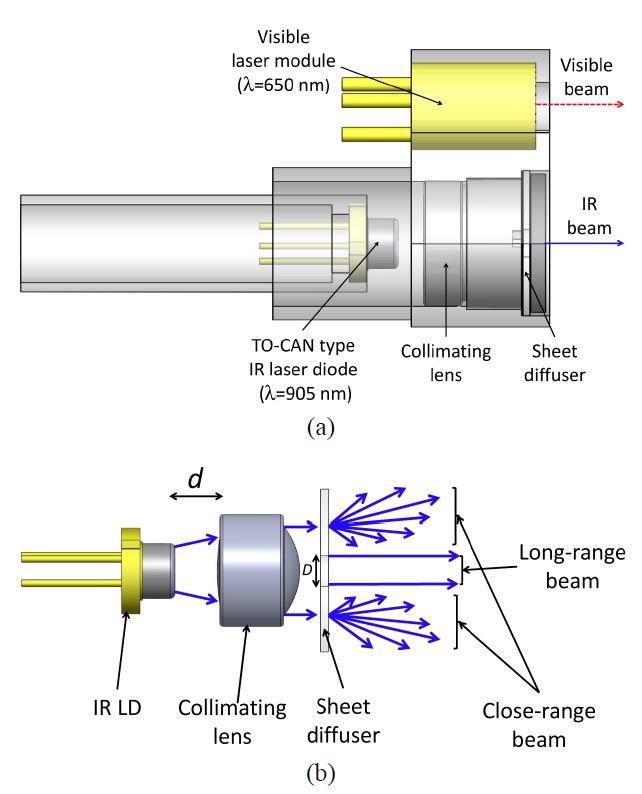
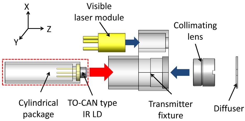
Our objective is to produce a compact IR beam transmitter, featuring an extended uniform trajectory, which can be monitored by a visible beam. The IR beam consists of both a highly collimated beam and a dispersive beam, which are responsible for the long and close range, respectively. Hence the coverage with a uniform detectable cross-section may be enhanced along the propagation direction. As illustrated in Fig. 1(a), the proposed transmitter entails IR and visible source modules that are vertically stacked. The IR module is made up of a TO-can type LD, a collimating lens, and a sheet diffuser that contains a circular aperture at the center. Similarly, a visible laser module, which is composed of a laser diode at 650 nm in conjunction with a compact collimating lens, was used to track the invisible IR beam. As depicted in Fig. 1(b), the beam emitted by the IR LD is collimated by the lens, and the inner part of the outgoing beam travels straight through the circular aperture so as to create a highly collimated long-reach beam. The rest of the beam, which resides outside of the aperture, is drastically dispersed by the scattering diffuser, resulting in a short-reach spreading beam.
Rigorous simulation based on a commercially available
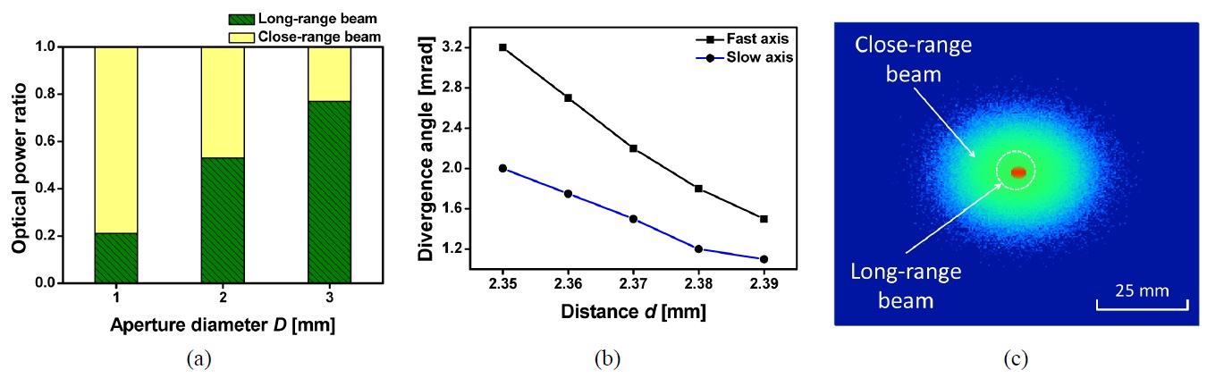
tool, Virtuallab from LightTrans GmbH, was conducted to design the proposed transmitter, taking into account the fact that the divergence of the long-range IR beam and the power ratio between the close- and long-range beams are dependent upon the aperture diameter
sufficiently collected, which has divergence angles of 28 and 8 degrees in the fast and slow axes, respectively. A sheet diffuser (Model LSD sheet from Luminit Inc.) was exploited to deform the incoming IR beam to diverge with an angle of 1 degree. We first investigated the power distribution associated with the close- and long-range beams with respect to the aperture diameter
III. REALIZATION OF THE PROPOSED BEAM TRANSMITTER AND ITS CHARACTERIZATION
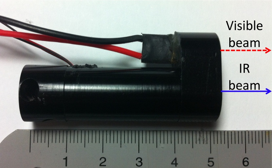
The embodiment procedure for the proposed laser transmitter is described in detail in Fig. 3. A fixture, wherein a visible LD module and a collimating lens are pre-installed, was combined with a TO-can type IR LD, which is mounted in a cylindrical package. The LD package was adequately adjusted in the transverse direction, while monitoring the alignment between the IR and visible beams. A thermally curable epoxy (Model EP-04 from AXIA) was then applied to fix the IR LD, which was also adjusted in the longitudinal direction so as to attain a desired beam divergence. The transmitter was completed by installing a diffuser sheet in the fixture. As displayed in Fig. 4, the prepared transmitter, with a length of ~5 cm, is equipped with two ports, supplying an IR beam at λ=905 nm in addition to a collinear visible beam at λ=650 nm.
For the IR beam emitted from the constructed transmitter, the measured slope efficiency, defined as the ratio of the optical output to the supplied electrical current, was ~0.9
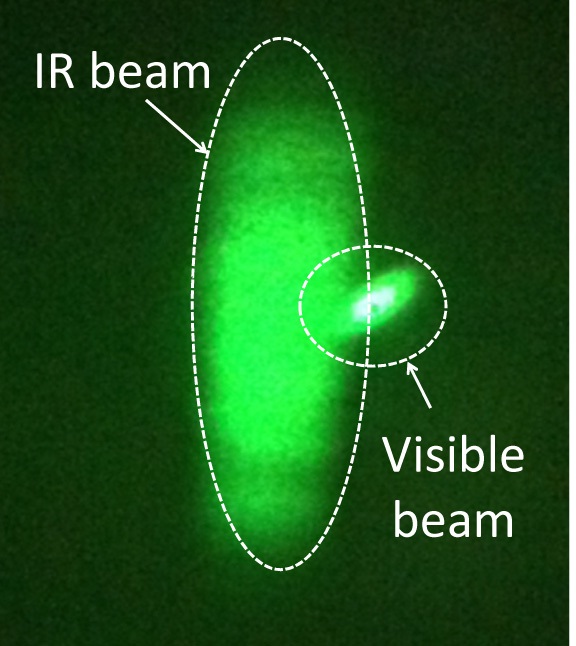
mW/mA. The ratio of the close- to long-range beam powers was observed to be approximately 1:1, as intended. The angular alignment between the long-range IR and tracking visible beams was explored, as described in Fig. 5, indicating that the deviation between the centers of the two beams, which are projected on a screen at a distance of 10 m away from the transmitter, was about 5 mm, translating into an angular alignment of ~0.5 mrad. In this work, in order to cover a human body of ~60 cm width at a distance of ~600 m from the transmitter, the angular alignment between the visible monitoring beam and the long-range IR beam is desired to be better than 1 mrad, which was readily accomplished. The visible beam spot was readily discernible with the naked eye at ~ 10 m from the transmitter, thereby accurately tracing the invisible IR beam. It is noted that the IR beam tracking is practically allowable, as long as the visible beam is comfortably recognized with the naked eye. Fig. 6 presents the captured profile of
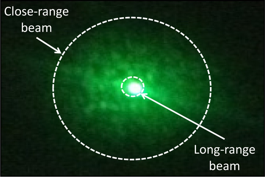
the propagating IR beam monitored at 1 m from the transmitter, comprising a long-range small collimated beam in the middle that is surrounded by a close-range broad beam. As designed, the divergence angles of the long-range beam were observed to be about 2.3 and 1.6 mrad in the fast and slow axes, respectively, whereas the close-range beam assumed a divergence of about 24 mrad. The complementary close-range dispersive beam is believed to help mitigate the blind spot immediately in front of the transmitter, referring to the region that is inevitably unreachable by the main IR long-range beam.
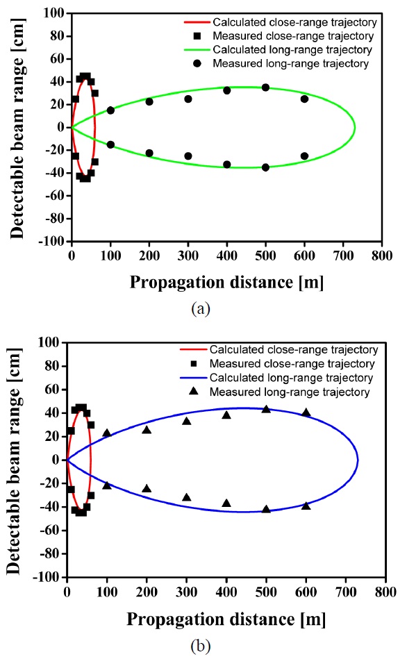
An outdoor field test was performed to validate the feasibility of the proposed laser transmitter in terms of the detectable beam trajectory. The IR beam was initially modulated, in accordance with the MILES communication code (MCC) standard, to produce optical pulse trains. The pulsed beam was propagated through free space and then captured by a custom-made receiver [14]. Figs. 7(a) and (b) present the observed and calculated results for the detectable beam width in the horizontal and vertical directions as a function of the propagation distance, respectively, for the two cases of close- and long-range IR beams. Here, the detectable beam width is defined as the maximum span in the transverse direction for the region, in which the propagating IR beam can be observed by a detector. The vertical and horizontal directions correspond to the fast and slow axes of the IR LD, respectively. It is noted that there is a good correlation between the calculated and demonstrated trajectories. The main long-range beam has been collimated to have small divergence angles of 2.3 and 1.6 mrad, assuming a gradually spreading beam profile along the propagation direction. Correspondingly, an effective trajectory of an elliptical pattern was obtained, the boundary of which is determined by a maximum detectable beam width at a specific position, with an average detectable cross-section of 60×80 cm2. The secondary close-range beam was witnessed to have a divergence of about 24 mrad, leading to a swiftly diverging short-reach elliptical trajectory, reaching up to ~70 m from the transmitter. In this respect, the complementary close-range beam was proven to efficiently overcome the blind region in the immediate vicinity of the transmitter, which is unavoidably missed by the long-reach highly collimated beam. Consequently, the overall effective trajectory of the transmitter could be uniformly extended by virtue of the complementary closerange beam, suffering from no serious blind spot.
We succeeded in developing a compact laser beam transmitter based on vertically stacked laser diode modules, delivering an IR beam that is precisely aligned with a tracking visible beam. The IR beam was adequately tailored to achieve a highly collimated long-range beam as well as a rapidly diverging close-range beam, by taking advantage of a sheet diffuser perforated with an appropriate circular aperture. Thanks to the complementary function of the long- and close-range IR beams, the demonstrated effective trajectory, exhibiting an approximately uniform detectable cross-section, could be readily extended up to 600 m, and was not susceptible to serious blind spots.