Satellite formation flying refers to multiple satellites executing a common mission in a formation. Satellite formation flying makes it possible to design the low-cost, high-efficiency mission, getting out of the limitations in existing space missions executed by using a single large satellite. In other words, by using several small satellites, the performance may be exhibited more efficiently, the burden on failure of the mission can be reduced, and the design of flexible mission becomes possible (Xu 2003). Hence, a variety of researches on the orbit and attitude are under way in order to implement the technology of satellite formation flying (Cho et al. 2008, Lim & Bang 2008, Yoo & Park 2011).
The integration of orbit and attitude control system is needed because the motion of satellite consists of orbital motion and rotational motion (Lennox 2004). Actually, there are lots of researches on integrated orbit and attitude control algorithm, and they are performed in largely two ways. One of them is to develop the orbit and attitude control algorithm independently and thereafter modify the control algorithm considering the effect of orbit and attitude integration (Naasz et al. 2003, Lennox 2004). The other one is to design the orbit and attitude dynamics as a single integrated dynamic model and calculate the values of orbit and attitude control using the dynamic model (Xin & Pan 2010, Wang et al. 2011, Wu et al. 2012). If the satellite is equipped with a complicated and sophisticated propulsion system, and thereby the orbit control can be performed at any time toward the desired direction regardless of the attitude of satellite, then the problem to integrate the orbit and attitude may become less important. However, in the case that the propulsion system is as simple as it is in a small satellite and has limited capacity, the integration of orbit and attitude becomes more important issue because the attitude of satellite should be oriented according to the direction of orbital thrust using limited fuel for orbit and attitude maneuver (Naasz et al. 2003). In other words, the main reason to integrate orbit and attitude control system is to minimize the waste of energy arising from the orbital maneuver performed toward the unintended direction.This becomes more significantin satellite formation flying because the formations are generally configured using small satellites and the satellites may have a low-thrust continuous propulsion system to maintain the relative orbit very precisely. (Wu et al. 2010). Therefore, the research on integrated orbit and attitude control algorithm is very important in satellite formation flying. In addition, it is also required to develop an integrated simulation system that can test and verify an integrated orbit and attitude algorithm because existing orbit or attitude simulation systems cannot be used separately to test the integrated algorithm.
The purpose of this study is to develop an integrated orbit and attitude control algorithm and an integrated software-in-the-loop (SIL) simulator that can test and verify the algorithm, and verify the integrated control algorithm using the integrated simulator developed. To this end, in the first place, an integrated control algorithm is developed using the orbit and attitude control algorithms developed in the past. State-Dependent Riccati Equation (SDRE)technique which is a non-linear control technique (Cloutier 1997) is utilized for orbit control, and the PD feedback control technique used in Jung (2010) is applied in order to maintain the attitude of satellite. In the integrated control algorithm, these two control algorithms are configured just like the actual satellite controls the orbit.
The integrated orbit and attitude SIL simulator is developed using MATLAB programming tool, which includes an orbit SIL simulator and attitude SIL simulator. The orbit SIL simulator mainly consists of true orbit generation, orbit determination, orbit control, and is designed to have the structure and performance similar to the GPS-based hardware-in-the-loop (HIL) simulator developed in Park et al. (2009). The attitude simulator consists of attitude propagation, attitude determination, attitude control, and is designed to have the structure and performance similar tothe 3 degrees-of-freedom HIL simulator developed in Kim et al. (2008). To verify the integrated SIL simulator with the integrated control algorithm, an integrated orbit and attitude simulation is performed for a satellite formation reconfiguration scenario on a low earth orbit. The goal of the scenario is to maneuver a user satellite from a relative orbit with 500 m baseline to a relative orbit with 1,000 m baseline.
In this study, an integrated orbit and attitude control algorithm is developed by integrating an orbit control algorithm and attitude control algorithm developed independently in the past. In Chapter 2, the previous orbit and attitude control algorithms are briefly addressed, and it is explained how the algorithms are integrated.
In the current study, the non-linear SDRE controller developed in Park et al. (2011) was used for the orbit control with some modifications. The SDRE controller calculates an optimal reconfiguration trajectory from a fixed point on the initial reference relative orbit to a fixed point on the final reference relative orbit.
To minimize the required energy, a performance index is defined as shown in Eq. (1).
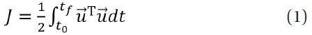
The performance index is restricted by the equation of state as follows.
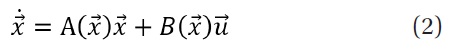
Eq. (2) represents the state-dependent coefficient (SDC)form designed to have the linear shape to use the SDRE technique. This equation is introduced in detail in Park et al. (2011). In addition, because the initial position and final position are fixed, the boundary conditions can be expressed as Eq. (3).

Then, the optimal control law is obtained as Eq. (4) by solving the two-point boundary value problem (TPBVP).

where

refers to a co-state variable. As shown in Eq. (4),
because
changes depending on the state variable, we should solve the TPBVP by applying the state variables changing at every step.
The optimal orbit control by Eq. (4) is performed generally as open-loop control. So, the control errors increase with time. In the current study, however, because the position and velocity of satellite are estimated at every step through the orbit determination process, the Eq. (4) can be calculated repeatedly based on feedback control theory by updating the position and velocity of satellite periodically at the boundary condition of
2.2 Attitude control algorithm
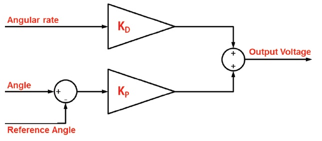
The PD feedback control technique developed in Jung (2010) is used for attitude control in the current study. Jung (2010) modified the attitude HIL developed by Kim et al. (2008) and used the PD controller in order to maintain the simulator in a desired attitude. Fig. 1 shows the block diagram of that PD controller. Although this controller was developed considering the possibility that it is used in the HIL simulator, it is possible to use it in the integrated SIL simulator in the same manner. First, the HIL simulator uses the information on angle and angular rates measured by attitude heading reference sensor (AHRS) hardware device while the SIL simulator uses the attitude values created by attitude determination process. In Jung (2010), the control values calculated through the PD controller is displayed at voltage unit and is used to drive the momentum wheel by controlling the motor. However, because the SIL simulator does not use the actual motor, the control values calculated by PD controller are converted from voltage unit into torque unit using the experimental relationship between the voltage and the torque. Eq. (5) relationship.

where
2.3 Integrated orbit and attitude control algorithm
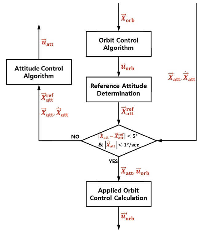
Using the orbit control and attitude control algorithm introduced previously, the integrated orbit and attitude control algorithm was developed. Fig. 2 shows the flow chart of the integrated orbit and attitude control algorithm. In the figure, the input values are
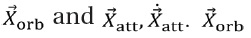
means the current position and velocity of the satellite, and

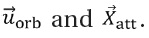
mean the current attitude and angular rate of the satellite, respectively. Then, ‘Orbit Control Algorithm’ calculates the orbit control vector

using the orbit control algorithm based on the current orbit information. According to the calculated orbit control, ‘Reference Attitude Determination’ determines the reference attitude

of satellite based on the direction of orbit control vector. If the attitude error between the current attitude

and reference attitude

is less than 5° and the angular
rate
is less than 1°/sec, the orbit control is executed. The attitude tolerance of 5° and angular rate tolerance of 1°/sec are the values determined in consideration of the performance of attitude control, and these conditions for orbit control execution prevent the orbit control from being executed when the satellite is oriented in a wrong direction or its attitude changes rapidly. Then, ‘Applied Orbit Control Calculation’ calculates new orbit control values

using the
In other words, the magnitude of

is the same as

and the direction of
accords with

If the conditions for orbit control execution are not satisfied, the orbit control is not executed during the time step, and ‘Attitude Control Algorithm’ calculates the attitude control values

using the attitude control algorithm so that the attitude of satellite

may accord with the reference attitude of satellite

Through the repetition of the above process, the satellite can achieve the desired reconfiguration maneuver by means of executing the orbit control and the attitude control by turns.
To develop integrated orbit and attitude SIL simulator system, the orbit SIL simulator enabling only the orbit simulation is developed in the first place, and then the integrated simulator system is developed by integrating the attitude simulation to the orbit simulator. In Chapter 3, the orbit SIL simulator and the integrated SIL simulator are explained.
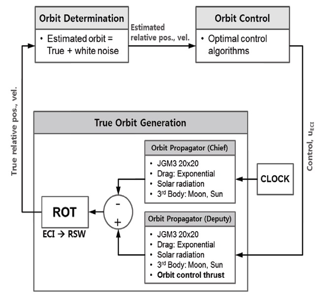
The orbit SIL simulator was developed using the MATLAB programming tool in order to test and verify a variety of orbit control algorithm of satellite formation flying. It has the structure and performance similar to the GPS-based HIL simulator system developed in Park et al. (2009). Fig. 3 shows the flow chart for the orbit SIL simulator developed. As shown in the figure, the orbit simulator mainly consists of ‘True Orbit Generation’, ‘Orbit Determination’, ‘Orbit Control’. First, ‘True Orbit Generation’ calculates the true position and velocity of chief satellite and deputy satellite at every step considering the several perturbations and orbit control value in Earth-Centered Inertial (ECI) frame. Then the position and velocity of two satellites are subtracted, and the true relative position and velocity are calculated through coordinate conversion into the RSW, satellite-centered coordinate system. In RSW coordinate, R-axis is defined as radial direction of chief satellite, S-axis as along-track direction, W-axis as cross-track direction, respectively. The applied perturbation models for orbit propagation include the Earth’s gravity field (Joint Gravity Model 3 up to 20 × 20), atmospheric drag (an exponential atmospheric density model), solar radiation pressure, and the solar and lunar gravity. In the ‘Orbit Determination’, the precise relative orbit determination is assumed to be a relative navigation using the GPS. So ‘Orbit Determination’ creates the estimated orbit data by adding the white noise error to the true relative orbit data generated in the ‘True Orbit Generation’ so that the estimation error is similar to that of relative navigation using the GPS measurements. The standard deviation (1σ) of errors for the white noise has the positional components of 2.634, 2.617, 2.103 mm, the velocity components of 0.802, 0.775, 0.688 mm/sec along the Radial, Along-track, Cross-track direction, respectively. Although the orbit determination process was simplified to be an error adding task, since it is based on the relative navigation results using hardware GPS simulator, the estimated relative position and velocity created in ‘Orbit Determination’ do not differ greatly from real navigation results. Based on the estimated position and velocity of satellite, ‘Orbit Control’ calculates the orbit control vector using the orbit control algorithm. Any kind of control algorithm using the information of position and velocity of satellite can be used as an orbit control algorithm. Finally, the calculated orbit control vector is converted into ECI coordinate, and is transmitted to the orbit propagator of deputy satellite in the ‘True Orbit Generation’. Therefore, the orbit SIL simulator is configured into the structure that can perform the overall closed-loop simulation.
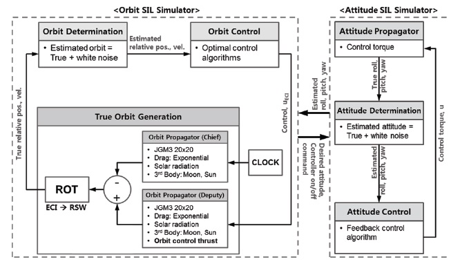
The integrated SIL simulator is developed to test and verify the integrated orbit and attitude control algorithm for satellite formation flying using MATLAB. Fig. 4 shows the flow chart of integrated SIL simulator which largely consists of ‘orbit SIL simulator’ and ‘attitude SIL simulator’. The ‘orbit SIL simulator’ is exactly the same as the orbit SIL simulator introduced in previous subsection, and the ‘attitude SIL simulator’ is added. In the attitude SIL simulator, ‘Attitude Propagator’ generates the true attitude data using an attitude dynamic model at every step. Then, ‘Attitude Determination’ creates the estimated attitude data by adding the white noise to the true data. The white noise reflects the statistical precision level of measurement obtained in the AHRS400CD which is an actual hardware device for attitude measurement, so its standard deviation (1σ) is defined as 0.5° for satellite attitude angle, and 0.06°/sec for angular rate. ‘Attitude Control’ can execute the application of feedback controller like PD, PID, Linear Quadratic Regulator (LQR). Finally, the calculated attitude control values are transmitted to the ‘Attitude Propagator’ again, having the overall closed-loop simulation as the orbit SIL simulator. Both of the orbit and attitude simulators exchange the necessary data each other in a manner that the orbit simulator transmits to the attitude simulator the information on reference attitude and on/off command for attitude controller while the attitude simulator transmits the current attitude information at every step to the orbit simulator.
Satellite formation reconfiguration simulations were performed by applying the orbit control algorithm to the orbit SIL simulator, and by applying the integrated control
algorithm to the integrated SIL simulator. The simulations were performed 5 times in total for each simulator, and the resultant graphs are displayed using the results of the first simulation. In Chapter 4, The scenario of formation reconfiguration is introduced, and the simulation results are explained in each simulator. Finally, the overall simulation results are compared and analyzed.
4.1 Formation reconfiguration scenario
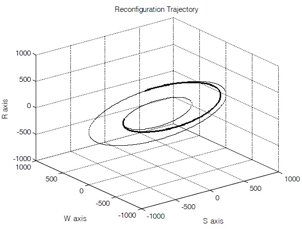
In the reconfiguration scenario,the semimajor axis of chief satellite was set as 7,000 km, the orbital eccentricity as 0.01, the inclination of satellite orbit as 60°, respectively. In addition, the initial orbit of deputy satellite was defined to have planar motion against the chief satellite. For the reconfiguration maneuver, the deputy satellite started on a point of planar motion with initial relative distance of 500 m, and reconfigured to a point of planar motion with relative distance of 1,000 m, and the maneuver time was set as 4,800 seconds. This maneuver time was selected by analyzing the required energy and the final reconfiguration errors of several simulations performed with different maneuver times. In addition, it was assumed that a thruster has a low-thrust continuous propulsion system. Fig. 5 shows the overall shape of planar motion, initial and final state variables, and the expected shape of reconfiguration trajectory.
The planar motion has the characteristic that the plane of relative orbit accords with the orbital plane of chief satellite. In other words, in RSW coordinate, the value of component (W-axis) vertical to orbit plane is maintained as ‘0’ (See Fig. 5). The advantage of the planar motion is that only two axes (R-axis, S-axis) are used for relative orbit
control. This means that the attitude of deputy satellite can be maintained toward the desired direction for orbit control by using attitude control with respect to only one axis.
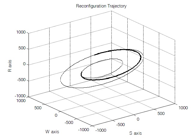
Figs. 6 and 7 show the simulation results using the orbit SIL simulator and the integrated SIL simulator, respectively. In the figures, the inner small orbit is the initial planar motion, and the outer large orbit is the final planar motion to arrive through reconfiguration maneuver. The middle trajectory is the simulated reconfiguration maneuver trajectory. As shown in the figures, the simulation results show almost the same reconfiguration trajectory, and the deputy satellite successfully performed reconfiguration maneuver over the final planar motion. In order to
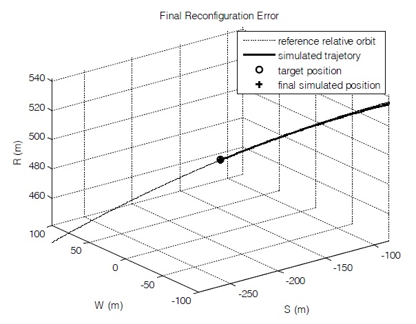
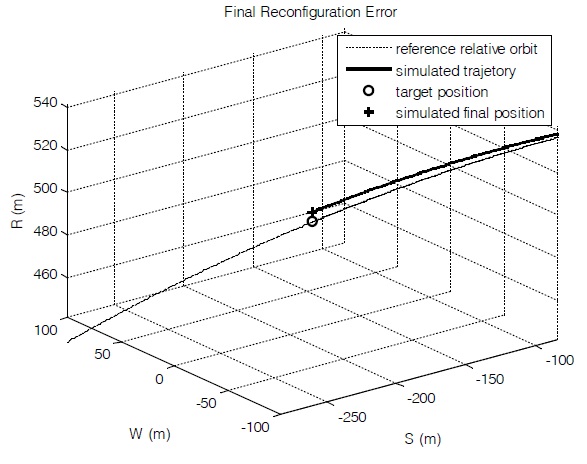
confirm the errors more in detail at the time of completed reconfiguration, the trajectories are enlarged in the final phase. Figs. 8 and 9 show the simulated trajectory at the final reconfiguration area using the orbit simulator and the integrated simulator, respectively. In the figures, the dotted line refers to final planar motion, ‘O’ mark refers to final desired position of reconfiguration, the solid line refer to simulated reconfiguration trajectory, and ‘+’ mark denotes final simulated position. As shown in Fig. 8, the deputy satellite arrived in the final desired reconfiguration position accurately in case of reconfiguration simulation without considering the attitude. The final reconfiguration error is 0.489 m, which shows the precision level within 1 m. However, in case of reconfiguration simulation considering the attitude, the final reconfiguration error was 4.852 m, ten times increased compared to the previous one as
shown in Fig. 9. In case of orbit simulation, it was assumed that the attitude control was performed correctly all the time. Therefore, the reconfiguration maneuver of the orbit simulation was performed more accurately compared to the integrated simulation considering the attitude control just like actual satellite.
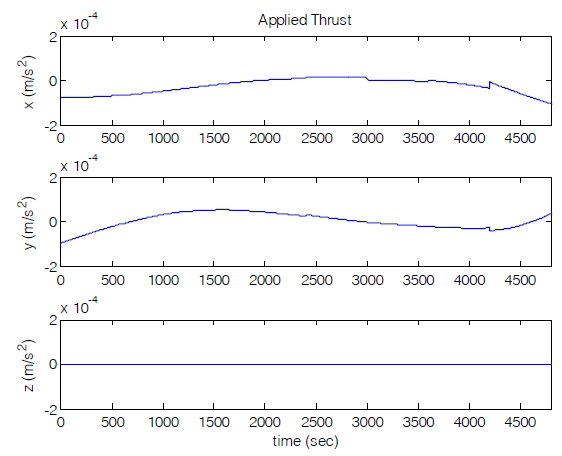
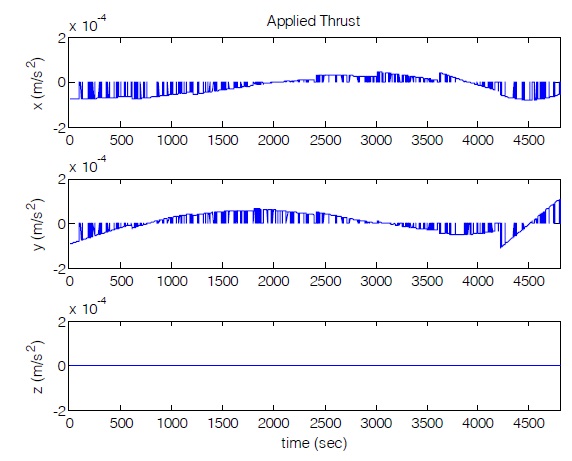
Figs. 10 and 11 show the orbit control profiles using orbit SIL simulator and integrated SIL simulator, respectively. In Fig. 10, the deputy satellite executes the orbit control without interruption. While, in Fig. 11, there are sections whose control values are ‘0’ at several scattered spots.In these sections, the attitude errors of satellite is larger than previously-defined tolerance, so the deputy satellite does not execute an orbit control and only conducts an attitude control instead in order to prevent the satellite from controlling the orbit toward wrong direction. In the both
Figs. 10 and 11, the orbit control values of W-axis are always zeros, because the reference relative orbit is a planar motion within the chief satellite’s orbital plane. Finally, in Figs. 10 and 11, the values of orbit control sharply change every 600 seconds, and this is due to the fact previously mentioned in explanation of orbit control algorithm. In other words, the orbit control values were calculated repeatedly by updating the current position of satellite every 600 seconds in order to prevent the control errors from being accumulated. The less the remaining orbit control time is, and the larger the accumulated orbit control errors are, the magnitude of the change of orbit control tend to increase in order to correct the accumulated errors. Thus, as the time of reconfiguration termination is approaching it shows the tendency well, which is represented more clearly in the integrated simulation rather than the orbit simulation.
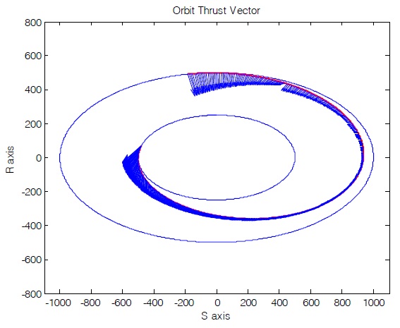
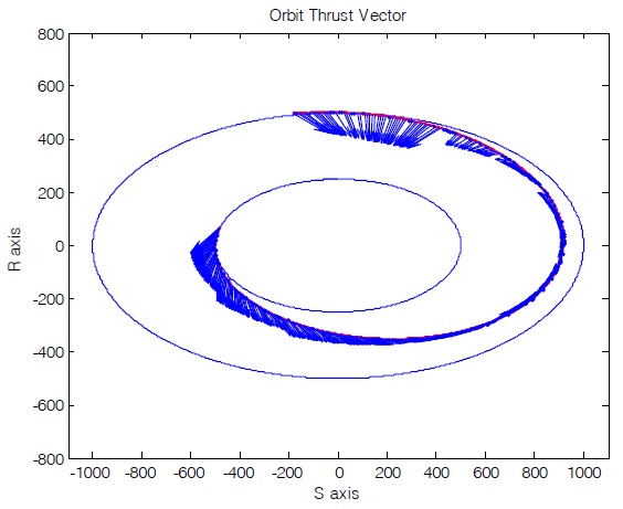
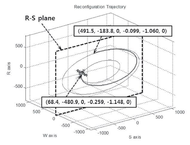
Figs. 12 and 13 show the changes in orbit control represented in Figs. 10 and 11 in a different way. The figures include the reference relative orbit on R-S plane, simulated reconfiguration trajectory, and arrows representing direction and size (the length of arrow) of orbit control vectors corresponding to that trajectory. Note that the shape of orbit and arrows are not projected on R-S plane, but all orbits and arrows are actually drawn on the R-S plane because planar motion was used as reference relative orbit. In Figs. 12 and 13, the overall patterns of trajectory and control vector are similar to each other. However, in Fig. 13, there are no orbit control vectors at some spots sporadically and that the size and direction of arrows change more sharply every 600 seconds compared to Fig. 12. These tendencies were also confirmed in Figs. 10 and 11.
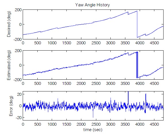
Finally, the results of attitude simulation can be confirmed only in the integrated simulation. Fig. 14 shows the results of attitude simulation using the integrated SIL simulator. The upper graph in the figure is the history of reference attitude of satellite which is desired attitude of satellite obtained based on the orbit control vector. The graph in the middle variation of the current attitude estimated from the ‘Attitude Determination’. Finally, the lower graph error between the reference attitude and the estimated attitude. As shown in the figure, the overall estimated attitude of satellite follows the desired attitude well, and the standard deviation of the attitude control errors was represented as 4.10°, and the average as -1.11°.
4.3 Analysis of simulation results
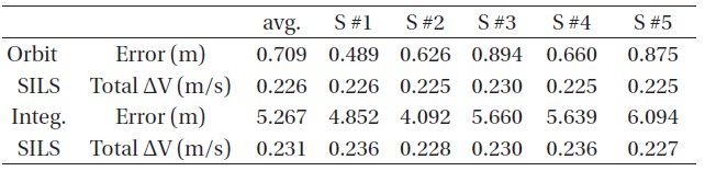
Table 1 shows the summary of simulation results using the orbit SIL simulator and the integrated SIL simulator.
[Table 1.] Simulation results of simulators.

Simulation results of simulators.
As shown in the table, the simulation was performed 5 times in total for each simulator. First, in the results of orbit SIL simulator, the final reconfiguration errors were all represented as within 1 m, and the total values of Δ
In this study, the integrated orbit and attitude control algorithmis developed for satellite formation flying and the integrated orbit and attitude SIL simulator system is also developed to test and verify the developed algorithm. Then, the formation reconfiguration simulation was performed using the orbit SIL simulator and the integrated SIL simulator, the simulation results were compared and analyzed. As a result, the final reconfiguration errors and total Δ