Colloidal systems have become an interesting research topic in areas from academia to industry over the past few years. Reflecting these trends, the field has been enriched by the introduction of liquid crystal (LC)-colloidal systems, in which the dispersive medium is LC materials [1]. A colloidal system that is applied to the liquid crystal display (LCD) can improve performance characteristics, providing low threshold voltage and fast response times, due to high dielectric anisotropy, reduction of the order parameter or a decrease in the screening effect [2-7]. In short, nanomaterial science research in LCDs has great potential to advance display technology. Many groups have reported LC doping with ferroelectric and ferromagnetic particles, metallic nanoparticles or inorganic nanoparticles such as Au, Ag, TiO2, carbon nanotubes and polymer-stabilized domain structures [8-15]. Some groups have shown that Sn2P2S6 and BaTiO3 nanoparticles increase the orientational order parameters of the LC mixture and the isotropic-nematic transition temperature [16-19]. Recently, Hwang et al. have shown that good LC orientation could be achieved without an alignment layer and the pretilt angle of LCs could be controlled in polyhedral oligomeric silsesquioxane (POSS)-doped LCDs [20-22].
In this study, we investigated the alignment properties of 6,13-bis(triisopropylsilylethynyl) pentacene (TIPS pentacene) doped LCs and the electro-optical (EO) characteristics of a twisted nematic (TN) cell with TIPS pentacene doped LCs. Previously, the properties of pentacene doped LCs such as EO characteristics, dielectric permittivity, and rotational viscosity were studied by H. K. Shin et al. [23]. However, study on soluble TIPS pentacene for LC was not yet reported. The TIPS pentacene which is known as a promising material for use in organic thinfilm transistors (OTFTs) [24,25] functioned as a charge trap for internal impurity ions. This contributed to a driving operation with a lower threshold voltage in the TN cells.
Indium tin oxide (ITO) is usually used as an electrode material in LCD applications due to its transparency, high conductivity, good etchability, hardness and good adherence on many types of substrates. Before preparing the LC alignment layer, the surface of ITO glass (Samsung Corning 1737) substrates were cleaned supersonically in acetone, isopropyl alcohol, and deionized water solutions sequentially for 10 min; then, they were dried using N2 gas. Cleaned ITO glass substrates were uniformly coated with homogeneous polyimide (PI, SE-7492, Nissan Chemical) by spin coating. The conditions of prebaking and imidizing for LC alignment were 80℃ for 10 min and 230℃ for 1 h. The final cured PI layer had a thickness of approximately 50 nm. PI layers were rubbed with a cloth to promote homogeneous alignment. The definition of the rubbing strength (RS) has been given in previous papers [26]. An RS of 300 mm was used on the PI surface in this experiment, and represents strong rubbing for LC alignment. These substrates were fabricated in an antiparallel configuration and TN cells with cell gaps of 60 μm and 5 μm, were used to measure the pretilt angle and electro-optical (EO) characteristics, respectively. Empty cells were then injected with pure and TIPS pentacene-doped LC by capillary action. Positive nematic LCs (MJ001929 from Merck,
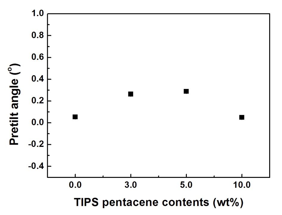
Based on the experiment described above, it was possible to prepare LC mixtures and uniform PI coated substrates. Following the preparation of elements, the behavior and orientation characteristics of TIPS pentacene doped LC mixtures on the rubbed PI layers were studied. LC alignment properties including pretilt angle and photomicrographs were observed to verify the practical application potential. Figure 1 presents the pretilt angles of TIPS pentacene doped LCs as a function of doping concentration in regard to TIPS pentacene. The resulting values were built up in a low range of angles from 0.05° to 0.28°, including adaptability to TN and IPS modes with a low pretilt angle. Also, these were found to be very similar values. This result indicates that the pretilt angle of the TIPS pentacene doped LC mixture was not affected by an increase in doping concentration.
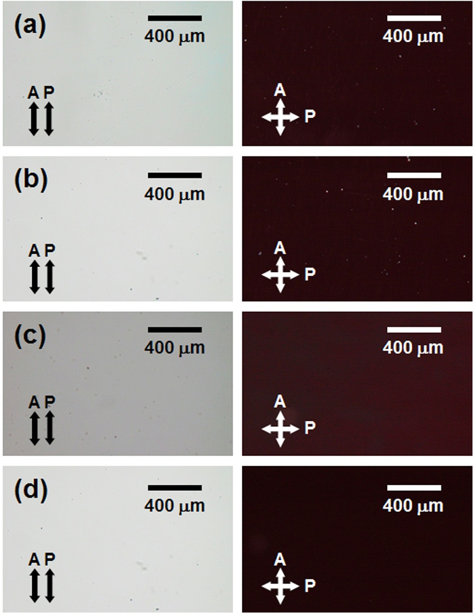
Figure 2 shows the photomicrographs (the polarizer is crossed Nicols) of the LC cell with TIPS pentacene doped LC as a function of doping concentration of TIPS pentacene. Good LC alignment without light leakage was observed in all samples. Clear and stable images of LC cells, regardless of the doping concentration, indicate that the TIPS pentacene/LC mixture was well dispersed. Also, TIPS pentacene doped LCs on the rubbed PI layer were not affected by the optical properties of the LC cell, and are therefore appropriate for LC applications.
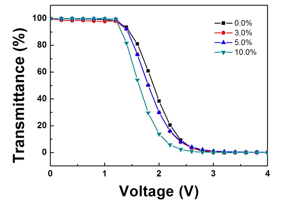
The electro-optical characteristics of TN cells with TIPS pentacene doped LC on the rubbed PI layer were confirmed to estimate their potential for LCD applications. Figure 3 shows plots of the voltage-transmittance (VT) curves of the TN cells. Excellent V-T characteristics were observed under all conditions. The threshold voltages of TIPS pentacene doped TN cells were less than 1.42 V (3.0 wt%: 1.42 V; 5.0 wt%: 1.42 V; 10.0 wt%: 1.31 V) at a transmittance of 90%, while one of the pure TN cells was over 1.46
V. The lowest threshold voltage for a TN cell (1.31 V) was shown at a 10.0 wt% doping concentration of TIPS pentacene. Threshold voltage decreased as the concentration of TIPS pentacene increased. This difference can be attributed to doping TIPS pentacene into the LCs, which induced increased dielectric anisotropy in the LCs. The dielectric anisotropy is an important parameter that defines the lower threshold voltage for LCDs [27]. Also, the reduced screening effect caused by ion charges within the TN cell might be an additional factor for threshold voltage suppression. The screening effect arising from the increased population of adsorbed ion charges on the alignment layer under an applied voltage across the TN cell causes a decrease in the effective voltage for the LC medium [28,29]. This screening effect increases the threshold voltage required for the display. TIPS pentacene can rectify the interface properties due to sufficient ion trapping via charge transfer in a field, and make the double-layer effect less effective, causing the observed amount of moving charges to decrease [28,29].
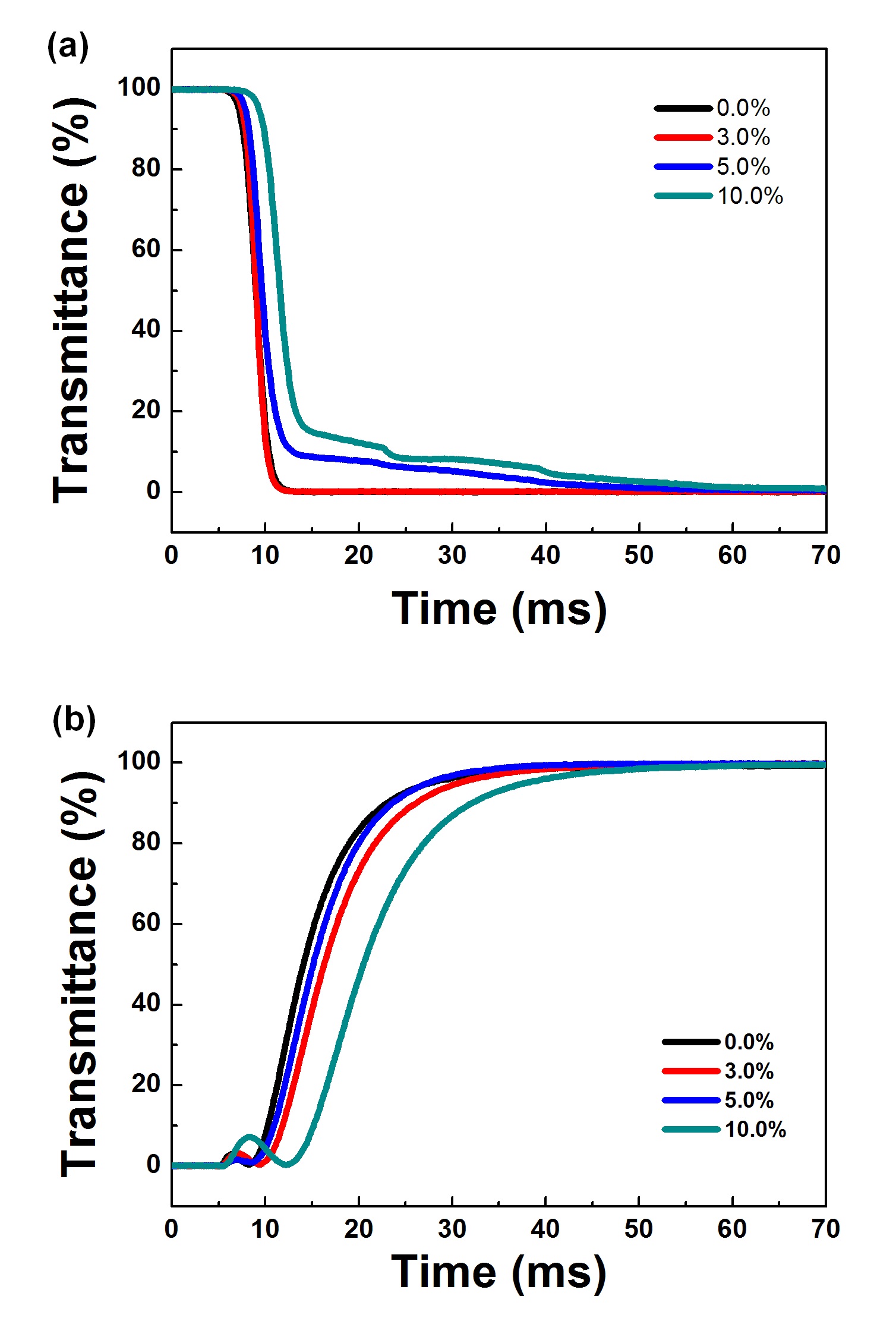
The response time characteristics including rising and falling time for the TN cells with TIPS pentacene doped LCs are shown in Fig. 4. Total response times were similar for pure LC and 3 wt% TIPS pentacene/LC TN cells, while those of high doping concentrations of TIPS pentacene increased as TIPS pentacene concentration
increased. In a previous study, response time increased in the CNT doped TN cell because of the increase in viscosity [30]. In this study, it is possible that the remaining solution that did not evaporate affected the response time. The response time performances of TN cells with TIPS pentacene doped LCs are summarized in Table 1.
In conclusion, we measured TIPS pentacene doped LC alignment properties on the rubbed PI layer as a function of doping concentration of TIPS pentacene, including pretilt angles, photomicrographs, and EO properties. The pretilt angles of TIPS
[Table 1.] Response time of TN cells with TIPS pentacene doped LC on the rubbed PI layer.
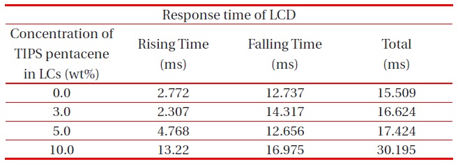
Response time of TN cells with TIPS pentacene doped LC on the rubbed PI layer.
pentacene/LCs on the rubbed PI layer varied in the low range of 0.05-0.28°, which are applicable to TN LCDs. No LC cells showed misalignment or local defects. Using a practical TN cell, excellent V-T characteristics were observed under all conditions. The threshold voltages of TIPS pentacene doped TN cells were measured to be 1.46 V to 1.31 V. The threshold voltage decreased as the concentration of TIPS pentacene increased. The TIPS pentacene doped LC had suitable response time characteristics for the TN LCD on the rubbed PI layer compared to conventional pure TN LCDs.