After the Industrial Revolution, many countries in the world developed their industries by thoughtlessly exploiting and abusing the natural resources of the Earth. As a result, as we moved into the 21st century, the amount of the natural resources of the Earth became depleted, causing resource-wealthy cou ntries to focus on their resource nationalism. Such a trend seems to be in the process of reinforcement. In such a situation, the countries interested in the development of the space are expanding the level of their national support for the researches on the unmanned planetary exploration for the investigation of resources on the Moon and the Mars which are located closely to the Earth in order to secure resources and colonialize each planet.
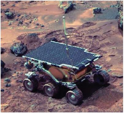
The world-first unmanned planetary exploration rover was Lunokhod 1 developed by Russia for the purpose of exploring the Moon in 1970 (cited 2012 Oct 5, available from: http://en.wikipedia.org/wiki/Lunokhod_1). After that time, National Aeronautics and Space Administration (NASA) of the US successfully set the lander named the Carl memorial station on the Mars in 1997 as part of Mars Pathfinder mission (cited 2012 Oct 5, available from: http://www.nasa.gov/mission_pages/mars-pathfinder). By using the Sojourner rover loaded on the lander, the exploration task for the soil and rocks of the Mars was carried out. The conceptual diagram of Sojourner is shown in Fig. 1.
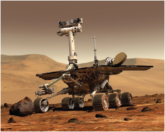
In 2004, the twin rovers, Spirit and Opportunity started to carry out their mission of exploring the Mars as part of Mars exploration rovers (MER) mission(cited 2012 Oct 5, available from: http://marsrover.nasa.gov/home/index.html). The conceptual diagram of Spirit and Opportunity is shown in Fig. 2.
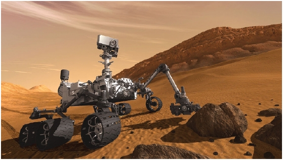
Since August, 2012, the rover, Curiosity has carried out its mission as part of Mars Science Laboratory (MSL) (cited 2012 Oct 5, available from: http://mars.jpl.nasa.gov/msl). It landed on the Gale Crater of the Mars and started to transmit the exploration data of the planet to the Earth. The conceptual diagram of the rover, Curiosity is shown in Fig. 3.
All those rovers which have either completed their missions of exploring the Mars successfully or been carrying out such missions contain the suspension systems equipped with wheels. It has been confirmed that wheels provide an efficient way of use in terms of weight, volume or the availability of control on an unknown surface compared to those with the caterpillar type or the foot type suspension system (Thueer et al. 2007). Because of such advantages, the main focus has been given to the development of the rovers equipped with the wheel type suspension system regarding the planetary exploration mission. However, it is impossible to remotely control the wheel type suspension system from the base on the Earth. Therefore, in case of free movements, it can be said that such a type shows weaknesses for its moving capacity on a specific unexpected surface.
In order to overcome such a shortcoming, the advanced countries in the field of space development have developed and improved the suspension system of the rover in various forms in order to make its movements stable (Kim et al. 2009).
This study set the height of the obstacle, which is one of the requirements for the designing process of the rover, as 150% of the wheel diameter in order to compare the operational capacity of the double 4-bar linkage suspension system for going over the obstacle, which is applied here, and the improved rocker-bogie suspension system (cited 2012 Oct 5, available from: http://www.nasa.gov, http://www.esa.int and http://www.cast.cn/CastEn/index.asp) applied to the rovers with the MER mission (Spirit and Opportunity) as well as the rocker-bogie suspension system (Hayati et al. 1997) applied to Sojourner of the US, which completed the exploring mission on the Mars. Then, by
carrying out a simulation, the excellence of the suspension system suggested by this study was verified. In Section 2, through the dynamic modeling process for each suspension system, the negative moments were induced. In Section 3, the simulation and its results for the negative moments based on the height of the obstacle were described in order to compare the overcoming capacities. In Section 4, a conclusion was provided.
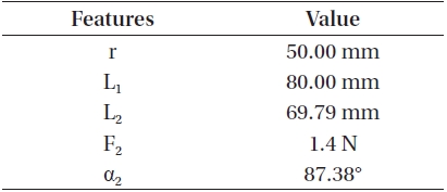
[Table 1.] Features about each rover
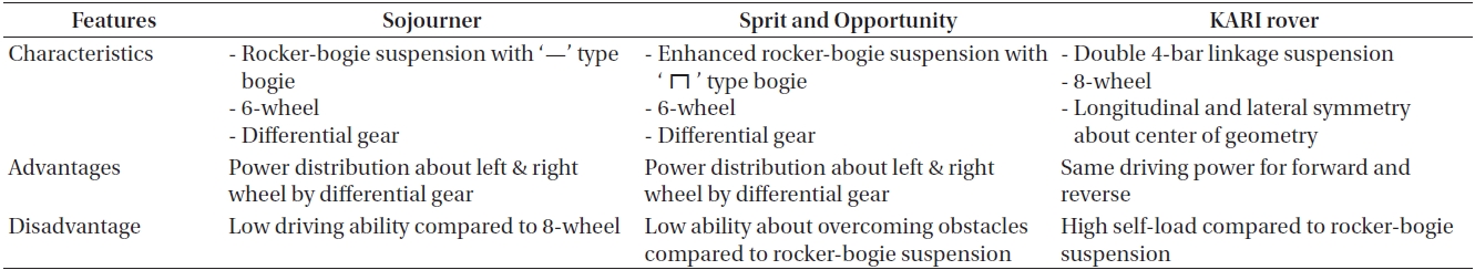
Features about each rover
2. DYNAMIC MODELING OF EACH SUSPENSION
The characteristics of the double 4-bar linkage suspension system suggested in this study and the comparable model of the rocker-bogie suspension system and the improved kind of rocker-bogie suspension system were described in Table 1. Also, the dynamic modeling process of each bogie was induced. The process of inducing the negative moments, which can be applied as the adverse function for the operational function of the rover for going over an obstacle and as a means of verifying the geometric designing process applied to the shape of the bogie, was described (Chen et al. 2009).
2.1 The Rocker-Bogie Suspension System
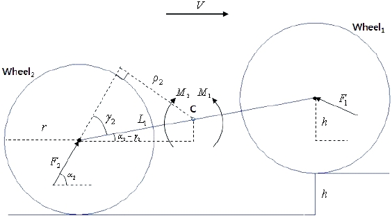
The rocker-bogie suspension system shows the form which was applied to the first Mars-exploration rover, Sojourner developed by NASA in the US in 1997. The Sojourner rover has the running gear consisting of six wheels attached to the front-back non-symmetrical suspension system (Fig. 1) composed of the rocker and the horizontal type of bogie. The maximum speed is 1 cm/sec. Also, it has the optimum mechanism of distributing equal share of weight to each wheel, making it possible to easily overcome an obstacle. It is known to overcome any obstacle with the height which is about 1.5 times bigger than the distance of each wheel (Sasaki et al. 2002). The free body diagram for the horizontal type of bogie is shown in Fig. 4. Here, r is the radius of each wheel, while L1 is 1/2 of the length of the horizontal type of bogie, h is the height of the obstacle, and F1 indicates the combined force among the momentum of the motor torque applied to the wheel No.1, the frictional force between the wheel and the surface, and the repulsive force applied by the wheel to each wheel. F2 is the combined force between the momentum of the motor torque applied to the wheel No.2, and the frictional force between the wheel and the surface. α2 is the angle which is shown between F2 and the horizontal side. M1 is the positive
moment applied as the proper function when the rover goes over the obstacle. M2 is the negative moment applied as the adverse function when the rover goes over the obstacle.
Eqs. (1-3) show the process of inducing the negative moments which reduce the operational capacity of the horizontal type of bogie applied to the Sojourner rover for overcoming an obstacle.
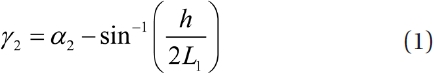


2.2 The Enhanced Rocker-Bogie Suspension System
The improved rocker-bogie suspension system (Figs. 2 and 3) is applied to the twin rovers, Spirit and Opportunity carrying out the MER mission. It shows the transformed shape of ‘┌┐’ which is different from the one shown by the horizontal type of bogie applied to the Sojourner rover.
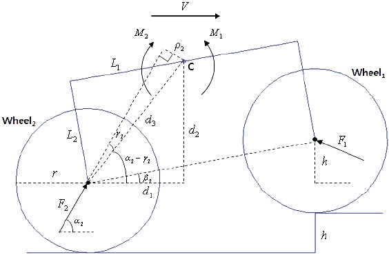
The maximum speed of the rovers, Spirit and Opportunity is 5 cm/sec, which is five times greater than the one shown by the Sojourner rover. The free body diagram for the ‘┌┐’ type of bogie applied to the rovers, Spirit and Opportunity is shown in Fig. 5.
Here, r is the radius of the wheel while L1,2 represent
1/2 of the length of the horizontal type of link with the ‘┌┐’ shape and the one of the vertical link respectively. h shows the height of the obstacle. F1 is the combined force among the momentum of the motor torque applied to the wheel No.1, the frictional force between the wheel and the surface, and the repulsive force applied to the wheel. F2 is the combined force between the momentum of the motor torque applied to the wheel No. 2 and the frictional force applied between the wheel and the surface. α2 is the angle between F2 and the surface. d1,2 indicate the horizontal element and the vertical one for the distance between the center of the wheel No.2 and the rotating center, C of the ‘┌┐’ type of bogie respectively. M1 is the positive moment, while M2 is the negative moment.
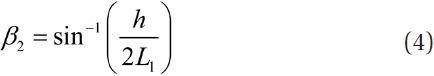
Eqs. (4-10) show the process of inducing the negative moments which reduce the operational capacity of the ‘┌┐’ type of bogie applied to the rovers, Spirit and Opportunity for overcoming an obstacle. It is possible to apply the horizontal and the vertical types of connection shown in Eqs. (5) and (6) not only to the case of a right angle but also to the cases of acute and obtuse angles.


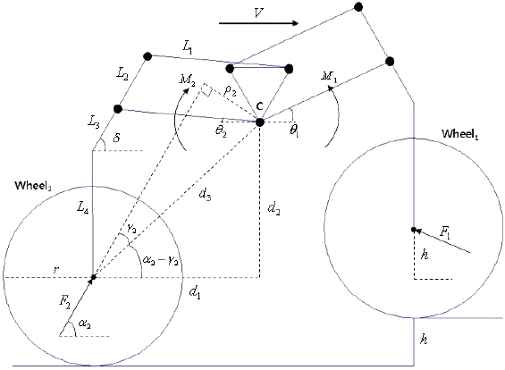
2.3 Proposed Suspension System
The suspension system suggested in this study shows the form of eight wheels attached to the double 4-bar linkage structure made by transforming and combining the two 4-bar linkage structures consisting of rockers and bogies. Based on its front, back, left and right symmetrical structures, the system carries out the same kind of operational function when moving forwards or backwards. Also, by additionally adding the motor carrying out the navigational function of the rover to each wheel, it is possible to easily rotate the rover in the same spot or make it turn a curve. The inverted triangular type of hinge connecting the front and the back 4-bar linkage parts shows the positions changing upwards and downwards based on the height of the obstacle. With such a function, each wheel can be moved upwards or downwards based on the height of the obstacle with the passive system. As a result, it is possible to easily control the rover and make it overcome the obstacle. However, due to the increasing number of links, there is a shortcoming regarding the increasing level of weight compared to the case of the rocker-bogie system (Eom et al. 2012). The conceptual diagram suggested in this study is shown in Fig. 6. The free body diagram for the double 4-bar linkage bogie applied to the suspension system is shown in Fig. 7. Here, r is the radius of the wheel, while L1,2,3,4 indicate the length of each link for the suggested suspension system. h is the height of the obstacle. F1 is the combined force among the momentum of the motor torque applied to the wheel No.1, the frictional force between the wheel and the surface, and the repulsive force applied to the wheel by the obstacle. F2 is the combined force between the momentum of the motor torque applied to the wheel No.2 and the frictional force between the wheel and the surface. α2 is the angle between F2 and the surface. θ2 is the angle between L1 and the horizontal side. δ is the angle between L3 and the horizontal side. d1,2 indicate the horizontal element and the vertical element for the distance between the center of the wheel No.2 and the rotational center, C of the suggested bogie respectively. M1 is the positive moment applied as the right function for overcoming the obstacle. M2 is the negative moment applied as the adverse function for overcoming the obstacle.
Eqs. (11-17) show the process of inducing the negative moments which reduce the operational capacity of the rover for overcoming the obstacle in regard to the suggested double 4-bar linkage. The inverted triangular type of hinge connecting the front and the back 4-bar linkage parts can show the positions changing upwards and downwards based on the height of the obstacle. θ2 is the function for the height of the obstacle. The counterclockwise direction is set to be ‘+’, while the clockwise direction is set to be ‘-’ for the inducing process.


The simulation to compare the capacity of overcoming
[Table 2.] Properties about the bogie of the rover Sojourner.

Properties about the bogie of the rover Sojourner.
[Table 3.] Properties about the bogie of rover Spirit and Opportunity.

Properties about the bogie of rover Spirit and Opportunity.
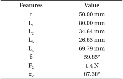
an obstacle can be applied under three assumptions. First, there is no slipping caused by the wheels on the surface. Such a point is one of the characteristics which should be considered in case of the high-speed operation. However, generally, it is ignored since it does not greatly influence the overall operational function of the rover even in case of the complex calculations when the robot or rover moves slowly (Kozlowski & Pazderski 2004). Secondly, the radius of the wheel is same as the length of the horizontal and the vertical links. Lastly, the combined force applied to each wheel is equal. In other words, the combined force applied to the wheel No.1 can be set equally in order to carry out the comparative analysis for the net negative moment values which can be utilized for the purpose of verifying the operational function of the rover for going over the obstacle in terms of the geometric shape of the bogie. Tables 2-4 show the arrangements of the property values for each suspension system subject to the simulation.
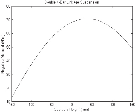
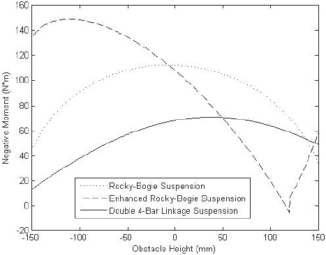
Figs. 8-11 show the values of the negative moments based on the changes of the 1 mm height for the range of -150 to 150mm, where the length of the obstacle is 1.5 times greater than the diameter of the wheel.
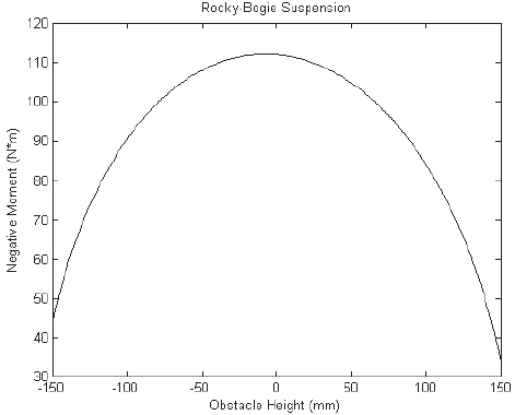
Fig. 8 shows the negative moments of the rocker-bogie based on the height of the obstacle. When the length of the obstacle is 0 mm, the maximum value is 112. When the length of the obstacle is 150 mm, the minimum value is 36. The amount of change is about 76 (N?m).
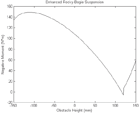
Fig. 9 shows the negative moments of the improved rocker-bogie based on the height of the obstacle. When the height of the obstacle is -110 mm, the maximum value is 148. When the height of the obstacle is 125 mm, the minimum value is -8. The amount of change is about 156 (N?m). When the height of the obstacle is 125 mm, there seems to be the non-consecutive kind of feature. Such a point means that the rover is turned over due to the pitch-
[Table 4.] Properties about the bogie of double 4-bar linkage suspension.

Properties about the bogie of double 4-bar linkage suspension.
over phenomenon of the rocker-bogie. As a result, when the height of the obstacle is greater than 125 mm, it is impossible for the rover to overcome the obstacle.
Fig. 10 shows the negative moment of the suggested double 4-bar linkage based on the height of the obstacle. When the height of the obstacle is 48 mm, the maximum value is 71. When the height of the obstacle is -150 mm, the minimum value is 14. The amount of change is about 57 (N?m). It shows a small difference between the maximum and the minimum values compared to those of other
suspension systems.
Fig. 11 shows the comparison between the responding characteristics for each suspension system based on the height of the obstacle. The negative moment of the suggested double 4-bar linkage suspension system is relatively smaller than those of other systems. Such a point means that it is possible for the rover to move with a relatively small amount of power due to the small level of frictional force applied to the surface when moving. Also, the amount of change for the negative moment based on the height of the obstacle is small, showing that the amount of influence given to the horizontal maintenance of the upper body composed of precise components is relatively small. As a result, it provides excellence in terms of the static stability.
This study compares a new kind of suspension system designed for the improved moving function of the planetary exploration rover and those shown by other rovers.
The negative moment values which can be used for the purpose of verifying the function for the geometric design of the bogie part are induced with the functions for the height of the obstacle. By comparing the responding characteristics for the operational functions of the rocker-bogie and the improved rocker-bogie suspension systems through a simulation, the excellence for the new suspension system is proved. Since it is difficult to fully understand the operational function of the entire system just based on the negative moment values, it will be necessary to induce dynamics for the center of gravity regarding the entire rover system in the future in order to compare and analyze the horizontal maintenance function of the upper platform composed of precise components together with the responding characteristics for the general surface environment. Through the experiment focusing on the rover prototype which is currently in the manufacturing process, it is planned to verify the excellence of the suggested suspension system.