Flutter refers to a serious aeroelastic instability in both civil and military aircrafts. The flutter phenomenon is characterized by limit-cycle oscillations (LCOs) of relatively high amplitude, exhibiting several harmonics. Modern fighter airplanes often carry many types and combinations of external wing-mounted stores to satisfy multi-mission requirements. Such stores can reduce the flutter speed and thereby degrade the operational and mission effectiveness of combat airplanes. Due to the importance of flutter avoidance, considerable research has been conducted in the last decades to develop and assess the capabilities of various flutter control concepts (Marzocca et al., 2002; Njuguna, 2007). In the general context of studies on semi-active/active methodologies, an important aspect is associated with the spatial optimization of actuator and sensor parameters to facilitate control of targeted modes while providing roll-off of higher-order modes without the need for phase-inducing filters. In contrast, the complexity inherent in semi-active/ active strategies for flutter control is dramatically reduced in passive systems such as VAs. Further, these systems exhibit desirable fault-tolerance characteristics.
A passive flutter control approach, known as the decoupler pylon, has been presented by Reed et al. (1980). The decoupler pylon isolates dynamically the wing from the store pitch inertia effects by means of soft-spring/damper elements assisted by a low-frequency feedback-control system that minimizes static pitch deflections of the store due to maneuvers and changing flight conditions. Wind-tunnel tests and analyses show that this relatively simple pylon suspension system provides substantial increases in flutter speed and reduces the sensitivity of flutter to changes in store inertia and center of gravity. The flutter characteristics of F-16 and F-17 flutter models equipped with decoupler pylon mounted stores are presented by Reed et al. (1980) and compared with results obtained on the same model configurations with active flutter control systems.
A semi-active flutter control strategy for high-aspectratio wings has been presented by Hu and Zhou (2007), where multiple magneto-rheological dampers are proposed. In their work, the results of the semi-active approach are contrasted with those obtained by the passive flutter control methodology based on multiple visco-elastic vibration absorbers (VAs).
A design methodology for optimized flutter control of an aeroelastic delta wing is presented by Richard and Clark (2003). Th ese experiments, employing optimized piezoelectric transducers, show substantially increased flutter control authority over non-optimized systems. They also point out the importance of this spatial coupling as well as the transducer mass and stiff ness eff ects. Works related to semi-active techniques can be found in Schweiger et al. (1999), McGowan (1999), and Rocha et al. (2007), while Njuguna (2007) presents a good review of existing techniques.
In the last century, nonlinear VAs have been proposed by purposeful introduction of nonlinearities in either stiff ness or damping. This nonlinearity can be associated with various aspects of the VA restoring force. For example, according to Lee et al. (2007a, b) the flutter and post-flutter control of a two-degree-of-freedom (two-dof) system is realized by a single-dof nonlinear energy sink (NES), which exhibits a nonlinear restoring force without the linear stiff ness term. The benefi t of this kind of VA lies in its ability to enhance the flutter speed or stabilize the post-flutter LCOs, depending on the initial conditions, flow speed, and mass ratio. Three diff erent control phenomenologies can be seen in the NES, and these are related to the diff erent interactions of the NES with the pitch and heave modes of the two-dof airfoil. In the first case, intermittent action of the NES results in intermittent oscillations of the three-dof system, and thus
flutter is not completely suppressed. In the second case, flutter is completely suppressed, while in the third case, stable LCOs arise in the post-flutter range. The results of this study, corroborated by experiments, showed a maximum increase of the flutter speed by 26 per cent.
With regard to material nonlinearities in the VA, Carpineto et al. (2010, 2011) and Vestroni et al. (2011) exploit the hysteresis exhibited by short wire ropes under fl exure to engineer a hysteretic VA for passive control of mechanical vibrations. In order to show the eff ectiveness of the proposed hysteretic VA, Carpineto et al. (2010, 2011) carry out a semianalytical/ numerical and experimental study of a simply supported beam equipped with the hysteretic VA, subject to harmonic and white Gaussian noise base motions.
In this work, a visco-hysteretic VA is investigated for flutter control of a thin airfoil with a careful unfolding of its nonlinear features in the pre- and post-flutter regime.
2. The Governing Equations of Motion
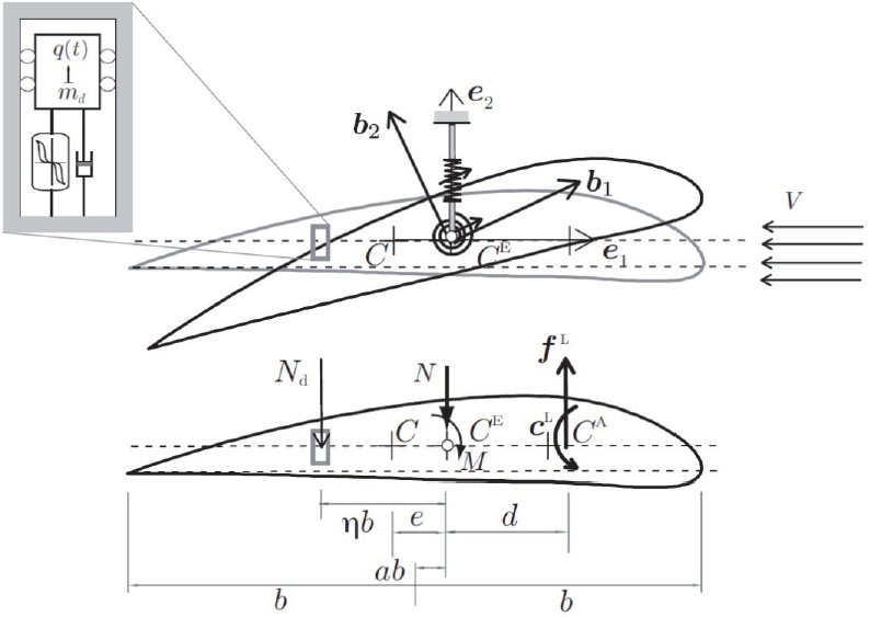
Studies of the flutter condition are often carried out considering a two-dof model of a wing treated as a lifting surface or a thin airfoil, accounting for the plunge and pitch degrees of freedom (Fig. 1). The flutter control strategy of this model is based on incorporation of a VA, located at a distance
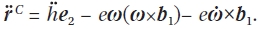
Let (

where
is the position vector of the material point in the current configuration with respect to the center of mass.
Let


where
and
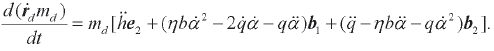
Therefore, the time rates of change of linear momentum and angular momentum of the lifting surface are given by:
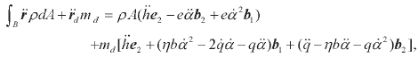
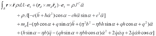
where
and
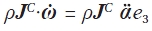
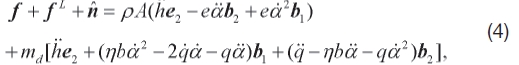
Thus, the balance laws of linear and angular momentum of the augmented system become:
where

and couple

acting on the lifting surface can be expressed as

The constitutive equation for the visco-hysteretic absorber,

can be written as a direct summation of an elastic part

and a dissipative memory-dependent part

according to

The dissipative part is, in turn, expressed as the summation of a linear viscous term and a purely hysteretic term z,
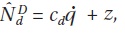
where the evolution of z is described by the Bouc-Wen first-order diff erential equation (Bouc, 1967; Lacarbonara and Vestroni, 2003; Wen, 1976).

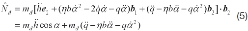
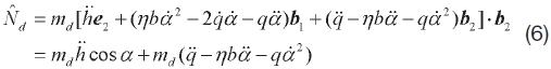
In Eqs. (4) and (5), (
Equations (4-6) are linearized, the incorporation of linear viscosity in the airfoil constitutive laws given by

At the same time, full nonlinearity is kept in the visco-hysteretic constitutive law for the VA. The ensuing equations are:


where ρ
According to Glauert’s theory of thin airfoils (Glauert, 1947), to obtain the aerodynamic forces induced by a uniform airstream of velocity
The lift force and aerodynamic moment, reduced to the aerodynamic center, are given by:
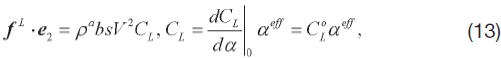

where s is the wing span, ρa is the fluid density, and
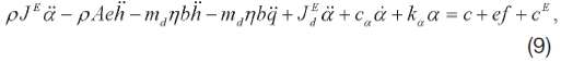
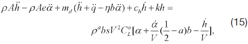
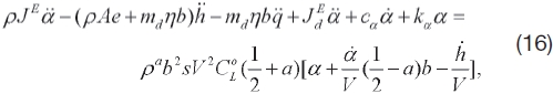
Therefore, the equations of motion, as a result of neglecting other kinds of external forces and considering only the linearized parts of the inertial and aerodynamic forces, become:


The dimensional constitutive parameters of the viscohysteretic VA are denoted by (
The next few paragraphs illustrate the non-dimensional form of the equations of motion of the augmented aeroelastic system. This form can be arrived at by dividing the vertical coordinate

the VA degree of freedom

the hysteretic variable z by z0 : =
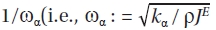
denotes the torsional frequency of the airfoil). As a result of these steps, the following non-dimensional form of the equations of motion can be obtained:

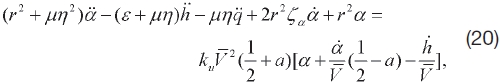


where the overbar is dropped in respect to
The most important nondimensional parameter in the design of the VA is the mass ratio μ : = ρ
Given the fact that the plunge frequency is
and the frequency of the VA by itself is
the following non-dimensional frequencies ratios arise from the non-dimensionalization:
(non-dimensional plunge frequency) and
(non-dimensional VA frequency). The non-dimensional pitch frequency becomes 1 in this case. The mass and elastic distribution properties of the lifting surface are summarized by
and ε : =
In contrast, the remaining non-dimensional constitutive parameters of the visco-hysteretic VA (besides

can be expressed as:

The non-dimensional velocity is
and the aerodynamic constant is given by
3. Design and Performance of the Aeroelastic Visco-hysteretic VA
The well-known Den Hartog visco-elastic VA (Den Hartog, 1934; Frahm, 1911) is widely regarded as effective for vibration cosntrol of a mechanical system subject to a harmonic timevarying force. This effectiveness is attributed to the antiresonance phenomenon, which completely cancels the response when the system and the VA are undamped and the frequency of the VA is exactly tuned to the frequency of
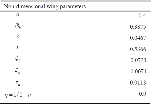
[Table 1.] Dimensional wing model parameters

Dimensional wing model parameters
the system driven to resonance. There is no exact resonance cancellation when the structure is damped, while the antiresonance phenomenon, accompanied by small amplitudes, is exhibited provided that the VA frequency is properly tuned to the frequency of the damped system.
Eight parameters must be determined to facilitate the design of a visco-hysteretic VA for flutter and post-flutter control. These parameters are the mass ratio μ, the position of the VA along the wing’s chord-wise direction η, the VA frequency

which arises from the tuning condition of the VA’s overall stiffness, the VA damping ratio ζ

When the hysteretic part of the restoring force z is discarded, the (dimensional) frequency of the VA can be expressed as
While ω

During flutter, it is expected that the VA will oscillate together with the appropriately phased airfoil so as to introduce additional damping into the augmented system.
A rational design of the VA consists of requiring ω
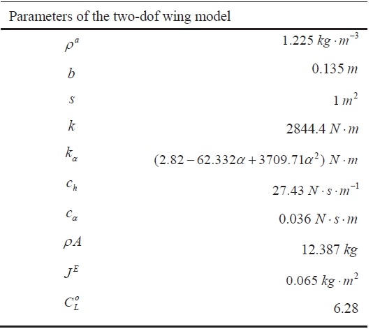
[Table 2.] Non-dimensional wing model parameters
Non-dimensional wing model parameters
flutter mode can be computed accordingly.
The mass ratio μ and the VA position described by η must satisfy certain physical restrictions. The weight limitation on the wing is such that the value of μ can be as high as 1/100 (an upper bound for the VA mass), while placing the VA at three-quarters of the chord toward the trailing edge leads to

These restrictions represent limitations on the magnitude of the control force. This force is greatly enhanced by higher mass ratios and by a position closer to the tip of the wing’s trailing edge, where the torsional couple exerted by the VA on the wing profile is maximized.
In relation to the VA damping ratio ζ
By adopting the parameters of the wing model studied by Behal et al. (2006), the application of the Routh-Hurwitz criterion leads to calculation of the non-dimensional linear flutter speed of the airfoil by itself found to be

The model in question is shown in Tables 1 and 2.
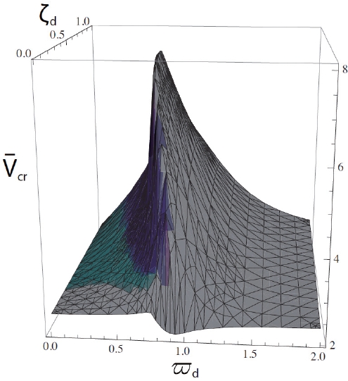
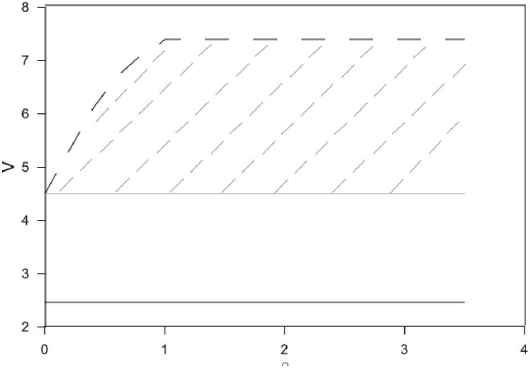
The optimal parameters for the linear visco-elastic VA can be determined by a numerical search calculating the flutter speed via the Routh-Hurwitz criterion on a grid that discretizes the parameter plane

in a lattice. Figure 2 shows the results of these computations, which lead to the following optimal parameters:

and ζ

and ζ

and if the damping ratio is set to ζ

and ζ
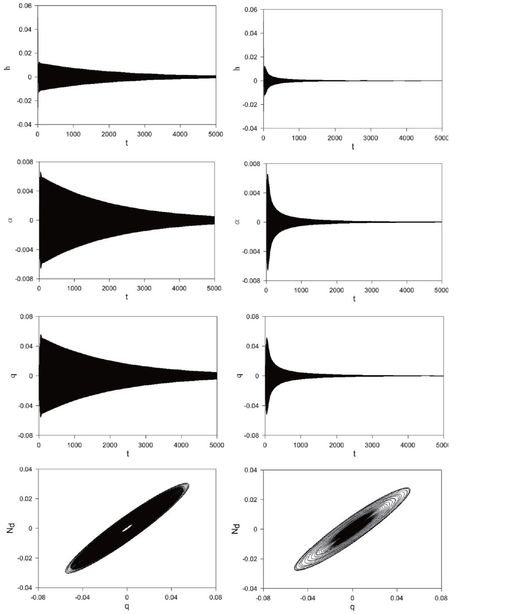
Numerical investigations via integration of the equations of motion into the effects of the visco-hysteretic VA (i.e., the parallel arrangement of a dashpot and a Bouc-Wen element) have shown that the purely hysteretic part of a system is unable to alter the flutter boundary of a system endowed with a purely visco-elastic VA. However, it does increase the effective damping of the system in the pre-flutter regime, as
shown in Fig. 3. The decay rate of the airfoil response to initial conditions is greatly enhanced by hysteresis. Moreover, the decay rate increases with the magnitude of the initial conditions up to a certain threshold, at which the effective damping is maximized.
It is interesting to study the effects of detuning in the optimal parameters of the visco-elastic VA while observing the effects of variations of the constitutive parameters of the hysteretic part of the VA restoring force. For example, in Fig. 4 the visco-elastic parameters are set to
and ζ

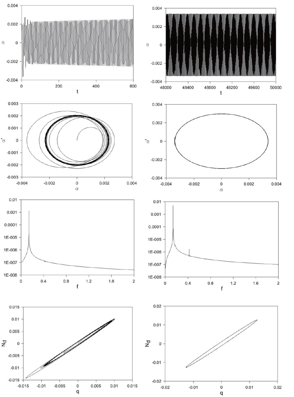
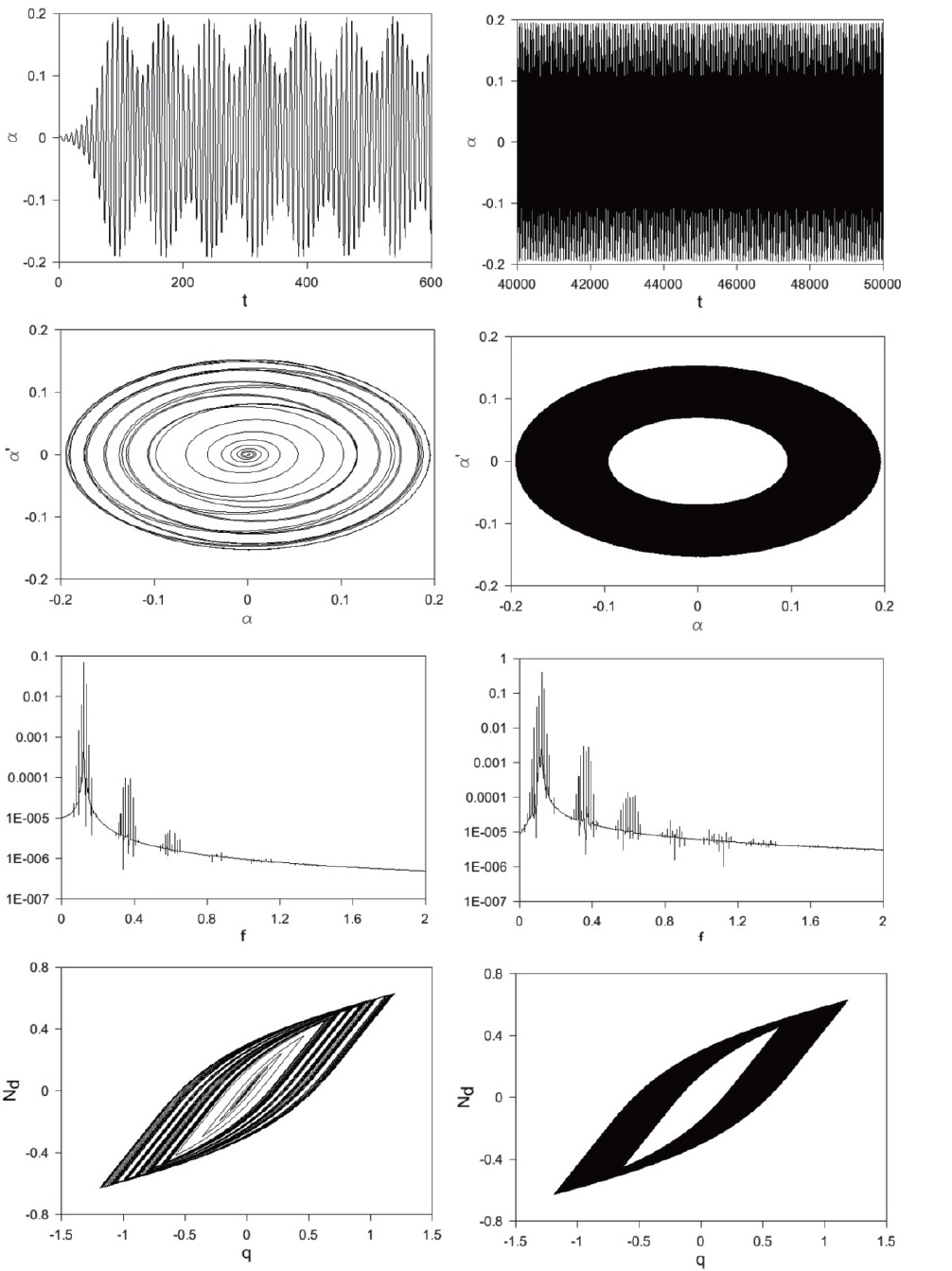
To assess the effects of the purely hysteretic component of the VA restoring force, the dashpot contribution is neglected and a set of post-flutter responses are shown in Figs. 8-10 with
at various flow speeds. While in the immediate vicinity of flutter, the LCO has one dominant frequency (the nonlinear flutter frequency); multiple harmonics of the flutter frequency are manifested at speeds further away from the flutter condition. More interestingly, when the flow speed is 3.66 times the flutter speed, the LCO undergoes a Hopf bifurcation by which the post-critical LCO becomes amplitude-modulated (i.e., quasiperiodic motion), as shown in Fig. 10.
In this paper, a visco-hysteretic VA is proposed in order to enhance the aeroelastic stability of an airfoil by increasing its flutter speed. The passive system is a parallel arrangement of a dashpot and a rate-independent hysteretic element, represented by the Bouc-Wen differential model (Bouc, 1967; Lacarbonara and Vestroni, 2003; Wen, 1976).
This paper shows that, for a set of parameters representing an experimental airfoil (Behal et al., 2006), the optimized purely visco-elastic VA (without the hysteretic element) can result in an increase of the flutter speed by up to 240 per cent when the mass ratio is 1 per cent. Numerical investigations are carried out into the effects of the purely hysteretic VA, i.e. a VA without the dashpot. These results show that a purely
hysteretic restoring force does not have the capability to change the flutter boundary of the airfoil, since at the onset of flutter the aeroelastic destabilizing forces can only be counteracted by a VA control force in which the resistive component depends on the relative instantaneous velocity. In contrast, the hysteretic restoring force can only dissipate energy over a full cycle of oscillation. However, the presence of a purely hysteretic restoring force enhances damping in the pre-flutter regime and controls the post-flutter behavior over a significant range of flow speeds.
The optimization described in this paper can be carried out in the presence of a visco-hysteretic force by applying the Routh-Hurwitz criterion, accounting for only the linear visco-elastic part of the restoring force. The primary effect of the hysteretic part of the restoring force is to increase the effective damping of the system in the pre-flutter regime, as shown in Fig. 3. In practice, the decay rate of the airfoil response to initial conditions is greatly enhanced by hysteresis. In the optimal configuration of the absorber, decay rates can only be controlled by hysteresis. This justifies its use in conjunction with the linear visco-elasticity of the spring and dashpot. The experimental validation of the control system is part of an ongoing research project.


![From left to right: (first line) time history of h, (second line) time history of α, (third line) time history of q, (bottom) loops of the total vibration absorber (VA) force, given respectively by Nd = 2ζd√δωdq and Nd = ωd2[δq + (1-δ)z]+2ζd√δωdq in t∈[0,5000] for the three-dof system with the linear visco-elastic VA (left) and with the visco-hysteretic VA (right). The flow velocity is V = 0.999 Vcr.](http://oak.go.kr/repository/journal/11327/HGJHC0_2011_v12n4_331_f003.jpg)
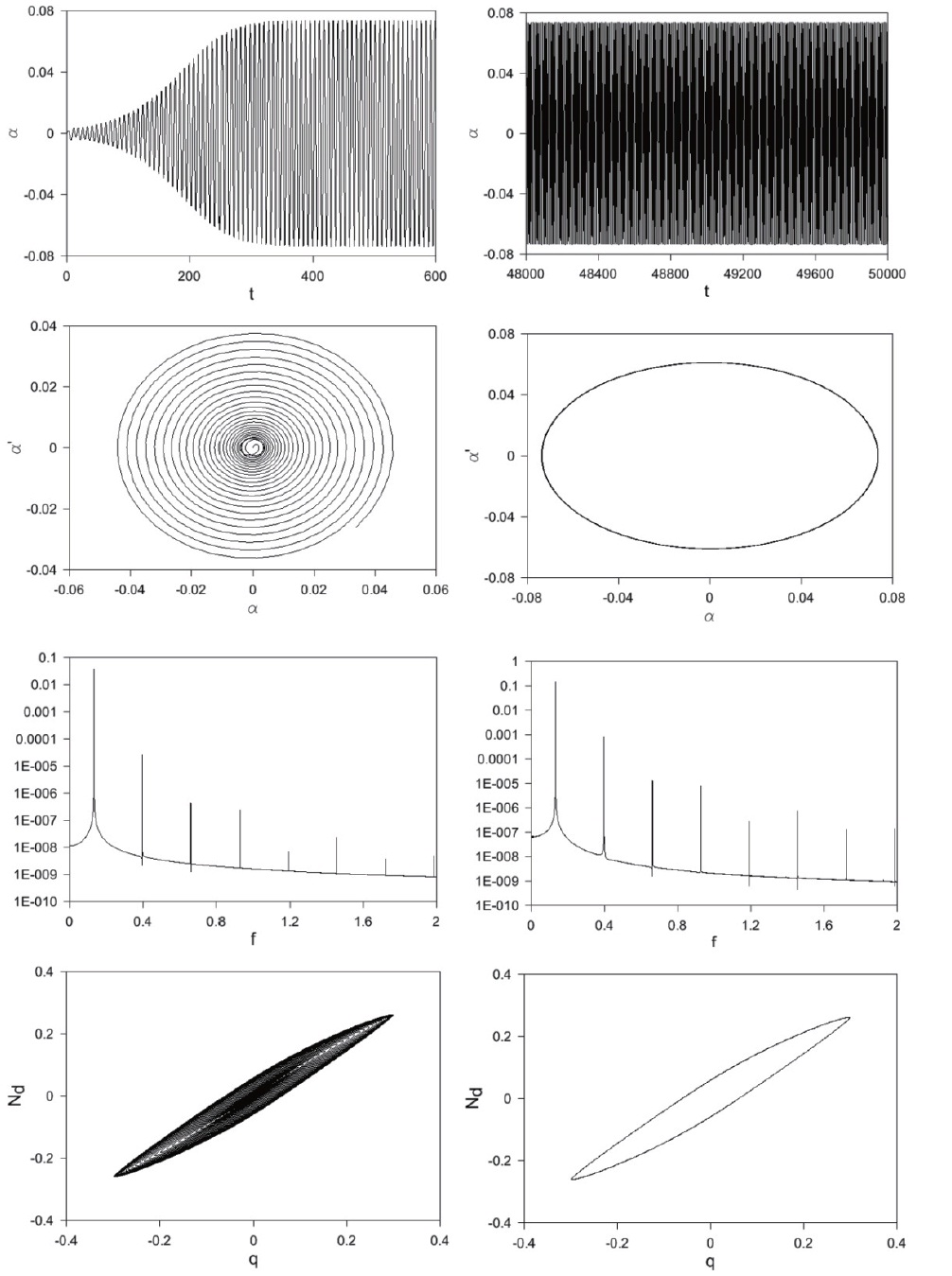
![From left to right: (top) time history of α and phase diagrams (α, α) in the transient phase (t∈[0,600] and t∈[0,200], respectively) and at steady state (t∈[4.8?104, 5?104] and t∈[3?104, 5?104], respectively) (middle) FFT of α and q, (bottom) loops of total vibration absorber force Nd = ωd2[δq + (1-δ)z]+2ζd√δωdq in the transient phase (t∈[0,600]) and at steady state (t ∈[3?104, 5?104]), when ζd = 0.1 and V = 1.02 Vcr with Vcr = 4.5. The peak in the FFT is attained by f = 0.14. f denotes the non-dimensional frequency.](http://oak.go.kr/repository/journal/11327/HGJHC0_2011_v12n4_331_f005.jpg)
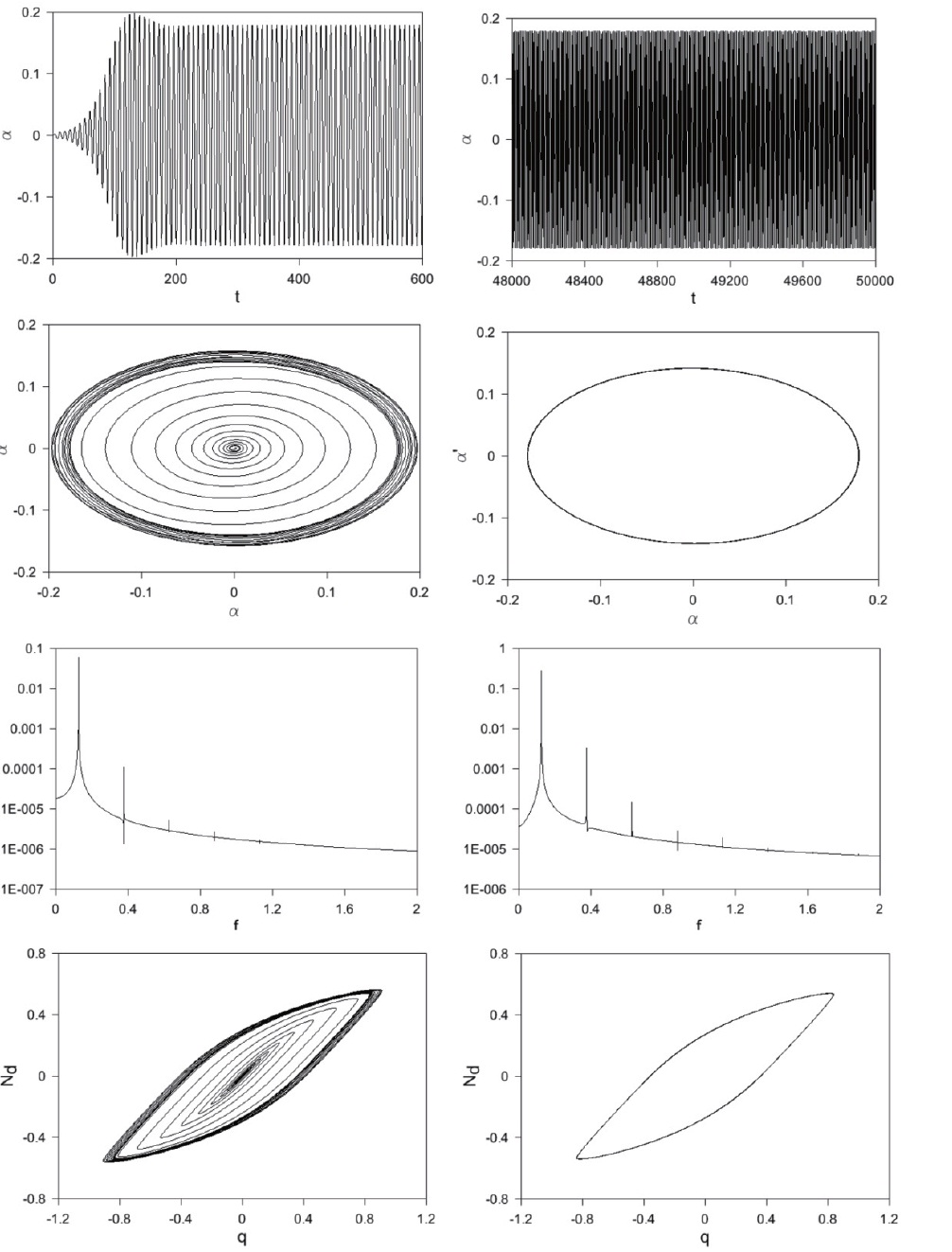
![From left to right: (top) time history of α and phase diagrams (α, α) in the transient phase (t ∈ [0,600] and t ∈[0,200], respectively) and at steady state (t∈[4.8?104, 5?104] and t∈[3?104, 5?104], respectively), (middle) FFT of α and q, (bottom) loops of total vibration absorber force in the transient phase (t ∈[0,600]) and at steady state (t ∈[3?104, 5?104]), when ζd = 0.1 and V = 1.33 Vcr with Vcr = 4.5. The peak in the FFT is attained by f = 0.132.](http://oak.go.kr/repository/journal/11327/HGJHC0_2011_v12n4_331_f006.jpg)
![From left to right: (top) time history of α and phase diagrams (α, α) in the transient phase (t ∈ [0,600] and t ∈[0,200], respectively) and at steady state (t∈[4.8?104, 5?104 ] and t∈[3?104, 5?104], respectively), (middle) FFT of α and q, (bottom) loops of total vibration absorber force in the transient phase (t ∈[0,600]) and at steady state (t ∈[3?104, 5?104]), when ζd = 0.1 and V = 1.64 Vcr with Vcr = 4.5. The peak in the FFT is attained by f = 0.14.](http://oak.go.kr/repository/journal/11327/HGJHC0_2011_v12n4_331_f007.jpg)
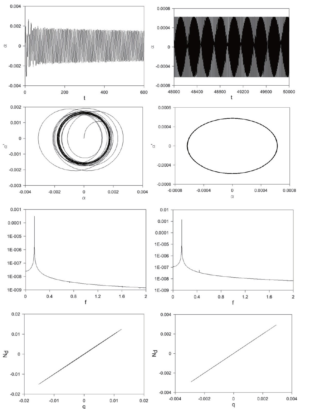
![From left to right: (top) time history of α and phase diagrams (α, α) in the transient phase (t ∈ [0,600] and t ∈[0,200], respectively) and at steady state (t∈[4.8?104, 5?104] and t∈[3?104, 5?104], respectively), (middle) FFT of α and q, (bottom) loops of total vibration absorber force in the transient phase (t ∈[0,600]) and at steady state (t ∈[3?104, 5?104]), when ζd = 0 and V = 1.05 Vcr with Vcr = 2.1. The peak in the FFT is attained by f = 0.146.](http://oak.go.kr/repository/journal/11327/HGJHC0_2011_v12n4_331_f008.jpg)
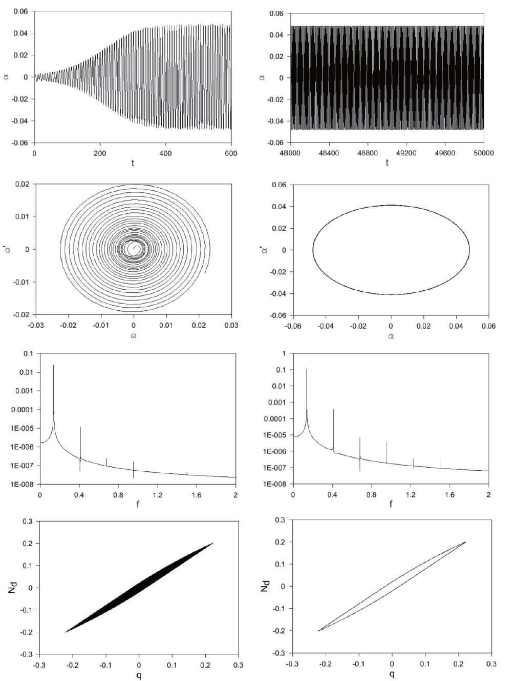
![From left to right: (top) time history of α and phase diagrams (α, α) in the transient phase (t ∈ [0,600] and t ∈[0,200], respectively) and at steady state (t∈[4.8?104, 5?104] and t∈[3?104, 5?104], respectively), (middle) FFT of α and q, (bottom) loops of total vibration absorber force Nd = ωd2[δq+(1-δ)z] in the transient phase (t ∈[0,600]) and at steady state (t ∈[3?104, 5?104]), when ζd = 0 and Vcr = 2.38 Vcr with Vcr = 2.1. The peak in the FFT is attained by f = 0.136.](http://oak.go.kr/repository/journal/11327/HGJHC0_2011_v12n4_331_f009.jpg)
![From left to right: (top) time history of α and phase diagrams (α ,α) in the transient phase (t ∈[0,600] and t ∈[0,200], respectively) and at steady state (t ∈[4?104, 5?104] and t ∈[3?104, 5?104], respectively), (middle) FFT of α and q, (bottom) loops of total vibration absorber force in the transient phase (t ∈[0,600]) and at steady state (t ∈[3?104, 5?104]), when ζd = 0 and V = 3.66 Vcr with Vcr = 2.1. The peak in the FFT is attained by f= 0.122](http://oak.go.kr/repository/journal/11327/HGJHC0_2011_v12n4_331_f010.jpg)