The ramjet-powered engine is regarded as one of the high efficient solutions for high speed and long flight distance from its first appearance during the 1900s [1]. However, due to its strong coupling effects between its flight condition and combustion mechanism, the study on the design of flight guidance/control of the engine has been limited by the complexity of propulsive characteristics affected by varying flight conditions.
The ramjet engine is an air-breathing system which uses incoming air-flow as a combustion oxidant, where the airflow is compressed through the shock generation mechanism with its intake shape (called ram-compression). Related with the nature of the ram-compression, it is known that the performance of the engine depends highly on not only its combustor conditions by fuel and exhaust nozzle actuations but the vehicle’s maneuvering during flight [2-4].
In spite of the difficulties in addressing the complex propulsion mechanism in vehicle model dynamics, there have been pioneer researches to design a flight controller of a hypersonic vehicle [5, 6]. They assumed that the thrust and aerodynamic effects follow designated parametric equations roughly defined with uncertainties. With the approximated control model equations, they used the adaptive sliding mode controller design method to achieve their objectives to control thrust (or velocity), altitude, etc. Recently, the controller design approach by the nonlinear adaptive method has been popularly used to design a controller of a hypersonic vehicle [7, 8] with more accurately developed nonlinear dynamic models for an air-breathing hypersonic vehicle as in Ref. [9, 10]. Although the control methods present the design processes with the dynamic models, which capture the characteristics of hypersonic vehicles (i.e. scramjet), the generalized approach for aerodynamic and propulsive properties approximated in equation forms is applicable in the work for a supersonic vehicle (i.e. ramjet).
In our previous study in Ref. [11], it is shown that the thrust of a considered ramjet engine is given from a tabular database in a function of Mach, altitude, angle of attack, equivalence ratio, and exhaust nozzle throat actuation, which are obtained by the engine model in Ref. [12]. With the thrust database, an approximated function for the thrust variation can be extracted where effecting variables and coefficients are varying with the flight condition for Mach and altitude. On the other hand, the aerodynamic properties of a supersonic vehicle can also be assumed to follow the functions regarding angle of attack and fin deflection angle for the control-design model (CDM) described in Ref. [8] since the aerodynamic characteristics of hypersonic vehicles are not much different from those of supersonic vehicles.
From the preceding discussions, a control model of a ramjet-powered vehicle can be obtained and it shows explicit dynamic relations between state variables and control inputs. In this paper, with explicit dynamic equations of a ramjet-powered vehicle, a nonlinear adaptive controller design is performed for a vehicle’s velocity to track a reference command, as the vehicle’s altitude is stabilized at a desired level by an altitude hold autopilot system. For the verification of the controller, several simulations are carried out with various types of velocity command functions.
Consequently, this paper is organized as follows. First, the generalized control model of a ramjet-powered vehicle based on previous studies [7-9] is defined where its thrust profile is approximated in the form of an equation through an engine performance analysis. Second, an overall procedure for the controller design of the vehicle is introduced, mainly disserting the nonlinear adaptive controller design for the velocity subsystem mainly. Finally, some discussion is followed after several simulations in order to demonstrate the controller.
2. Ramjet-powered Vehicle Dynamic Model
In this section, we derive a control-oriented version of the model for the longitudinal dynamics of a ramjet-powered vehicle dynamic model. The simplification is necessary to overcome the analytical intractability of the original model, which will be henceforth referred to as the true model. For the sake of simplicity, the scheme for a control-oriented model in Ref. [9] is employed in this study. The controloriented model, after the procedure of the simplicity, finally represents the explicit state space equation.
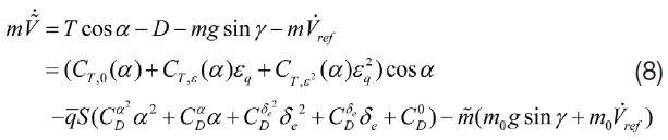
In general, the nonlinear longitudinal equations of motion are given as
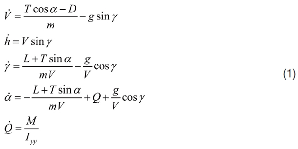
This model is composed of five rigid-body state variables
On the other hand, in order to control the vehicle’s velocity, it is necessary to approximate the terms for
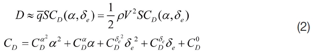
The approximation in Eq. (2) is linear in its fit parameters and the parameters are assumed to vary with flight conditions for Mach number
2.2 Thrust Variation Tendency and its Approximation
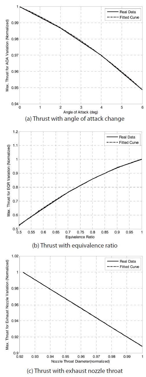
As mentioned, the thrust of the ramjet engine is a function of five parameters (Mach number, altitude, angle of attack, fuel flow rate, and nozzle throat area). Here, the fuel flow rate is replaced by the equivalence ratio which is the actual air fuel ratio/the air fuel ratio for the stoichiometric mixture.

Prior to initiating the investigation for the influence of the parameters on thrust, in this paper, the flight conditions for Mach number and altitude are excluded as focusing on the internal loop variables for
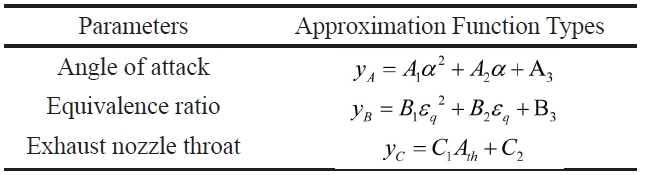
[Table 1.] Approximated Thrust Functions

Approximated Thrust Functions
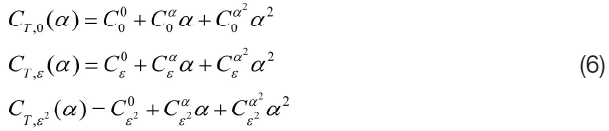
From the results in Fig. 1 and Table 1, it is acceptable that the thrust can be defined as a function of

In Eq. (4), there are two main control inputs for thrust,

where
In this section, a procedure on the design of a velocity controller is mainly shown by using an adaptive nonlinear approach. Besides, we briefly mention the process of an altitude hold autopilot design.
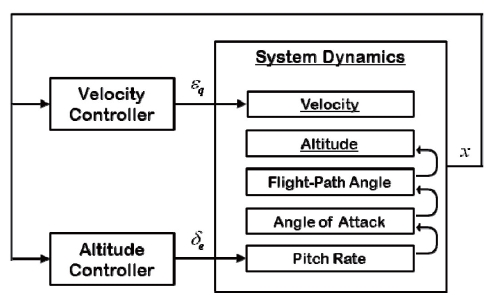
The controller design starts from the decomposition of the equations of motion into functional subsystems, namely, the horizontal translation dynamics (the velocity subsystem) and the vertical translation dynamics (the altitude subsystem). Each subsystem is controlled separately using the available inputs at that level and intermediate virtual control command, as shown in Fig. 2. In particular, as an extension from the preceding discussions, a control law with adaptive compensation is derived for the velocity subsystem by controlling thrust from the input of the fuel equivalence ratio,

using feedback from the state

indicates the vector of uncertain parameters. On the other hand, the altitude dynamics are controlled by means of the missile fin deflection angle actuation,
3.1 Adaptive Nonlinear Controller Design for the Velocity Subsystem
The control law for the velocity subsystem is derived by using robust adaptive dynamic inversion. By substituting the expressions of
where

Define the vector of uncertain parameters as

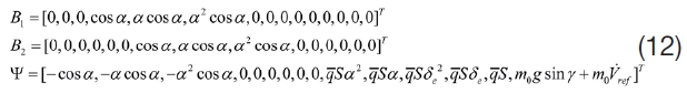
The components in Eq. (10) indicate the whole parameters in Eqs. (2) and (6), and they are to be estimated with sequences in the control law generation algorithm. Then, the error dynamics in Eq. (8) can be rewritten with additional vectors for the simplicity of the equation as follows.

where
In the adaptive nonlinear controller scheme, we want to regulate the variable,

and the estimation error for the uncertain parameters,
To achieve this goal, we consider the Lyapunov candidate function below.
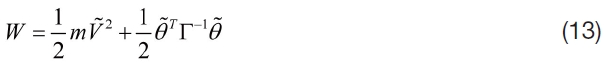
where

Here, the term

on the right hand side of Eq.(14) is from a perception as

In order to satisfy the condition in Eq. (14), the updated law of the given uncertain parameter vector

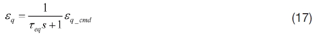
The control law for the velocity stabilization is derived from Eq. (15) and the one feasible solution from the quadratic equation can be used as the equivalence ratio command. Here, the fuel supply actuation by this command is assumed to be the 1st order dynamics, with a cutoff frequency of approximately 0.8 Hz [13], which is equivalent to a time constant
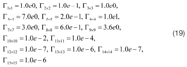
In addition, in this paper, the diagonal positive definite gain matrix Г for the velocity subsystem is constructed after considering the order of each value regarding uncertain parameters. From the true model of the engine under the given flight conditions, the uncertain parameters can be given roughly, which are used for their initial guess. If the motion of the ramjet engine is trimmed at the flight condition of Mach 2.9 and an altitude of 14km, the initial estimation for the uncertain parameters are shown as
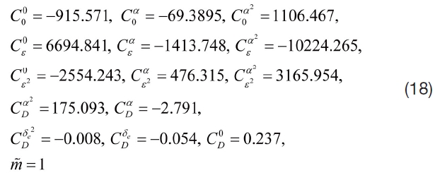
The values in Eq. (18) are approximately obtained by fitting the tendencies of the variations in thrust and drag for the independent variables (angle of attack, equivalence ratio, and fin deflection angle). For example, the sample variations in drag with the change of fin deflection at the trimmed value are fitted as the second order polynomial such that the values of

and

can be obtained.
Considering the order of the uncertainties, the components of the gain matrix Г are
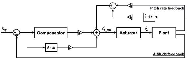
3.2 Altitude Hold Autopilot Design
When a reference altitude command,
In the control sequence, the pitch rate feedback and altitude feedback are considered to generate fin deflection angle command
In this section, the controllers constructed in the preceding section are examined in several simulations. The simulations begin from an initial trim condition. For the trim condition, it is assumed that ramjet engine maintains normal operation during level flight at Mach 2.9 and an altitude of 14 km. In addition, it is noted that the initial guess and gains defined in Eqs. (18) and (19) are consistently available in the simulation.
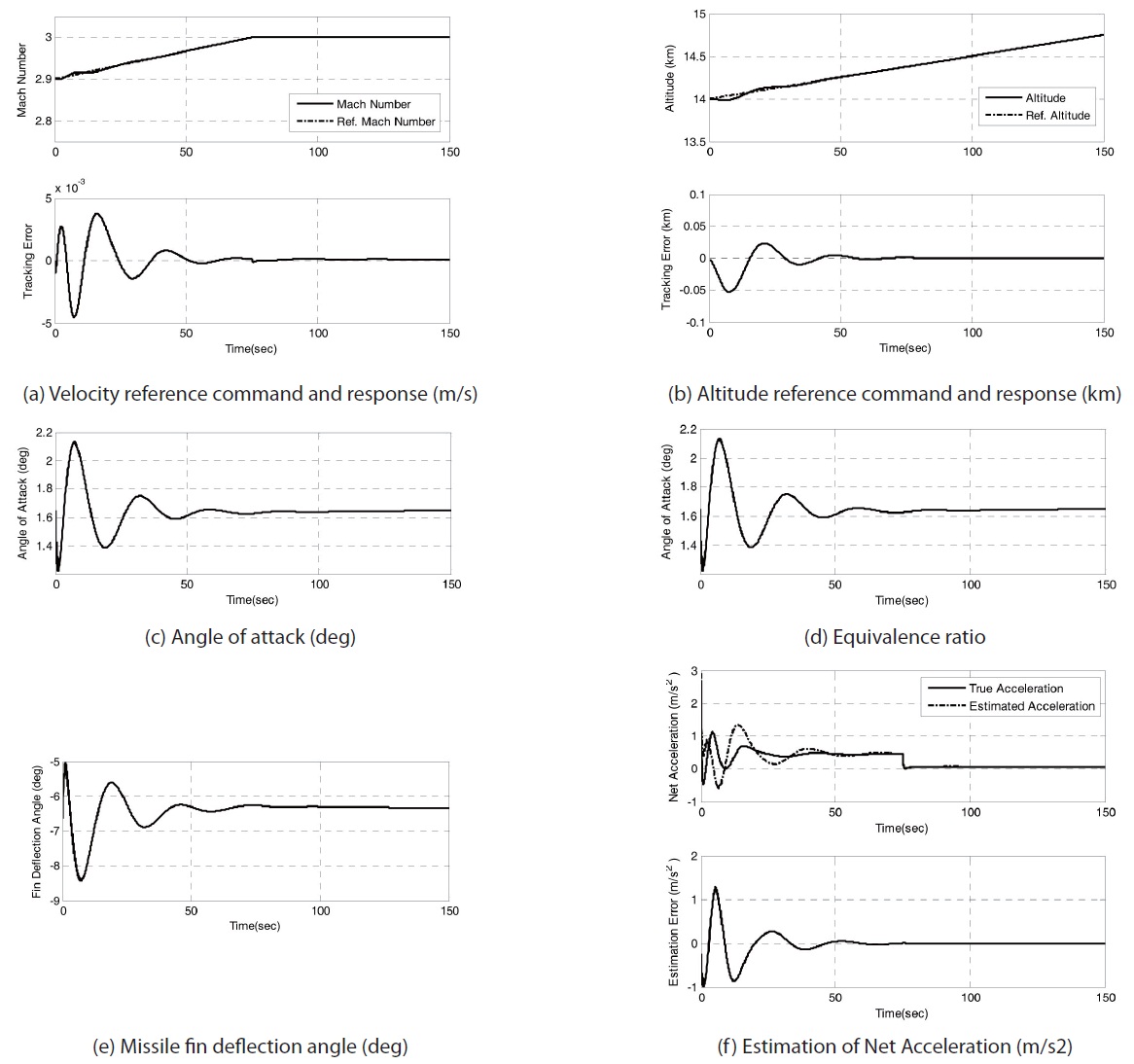
To demonstrate the control algorithm, we consider two scenarios, in total, with different velocity commands. The first scenario is made for linear velocity and altitude commands. The results are shown in Fig. 4. The velocity command is linearly increasing, equivalently, from Mach 2.9 to 3.0. After reaching Mach 3.0 the velocity command is maintained to that level. The altitude reference is also given linearly from 14 km with an increment rate of 5 m/sec. From the result, it is shown that the engine needs to consume more fuel supply with increasing velocity and altitude from trimmed states. After reaching reference commands, the maneuver of the vehicle (by equivalence ratio and missile fin deflection) is both stabilized with little variation.
In order to stabilize the error of the vehicle’s velocity for a reference command, the estimation of nonlinear controller results in fine tracking of net force (or net acceleration) along to the velocity vector. As described, the nonlinear velocity controller estimates the vehicle’s thrust and drag with the approximated functions in Eqs. (2) and (4). However, the nonlinear controller takes only one feedback, the velocity error, such that the number of estimation is not matched with that of the stabilization objectives. Therefore, it may not be guaranteed that the estimations both in thrust and drag are converged to their real values, but only the converged estimation of net force (or net acceleration) is secured (see Fig. 4.(f )).
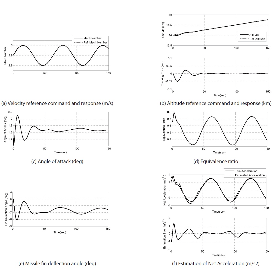
The second case is for the sinusoidal velocity reference wherein the other conditions are the same as in the first scenario. This simulation might help to verify the control performance with an arbitrarily varying control command. The reference command is assumed to be a sinusoid Mach function with an amplitude of 0.1, a frequency of 0.1 (rad/s), and a mean value of 2.9. The results are shown in Fig. 5. From the simulation, it is shown that the velocity and altitude command are well tracked by both controllers for corresponding subsystems. The velocity change is delayed by roughly π/2(rad) to the fuel supply as expected in the motion
dynamics, and the fin deflection actuation is consistent with the velocity, which needs to stabilize the altitude by the velocity change. Furthermore, Fig. 5(f) demonstrates that the estimation of the net acceleration is continuously converged with time.
In this paper, an approach on the controller design of a ramjet-powered vehicle is introduced. The ramjet-powered vehicle has a coupling effect of the vehicle’s flight condition and propulsive performance such that the thrust is one of the major factors under varying instantaneous flight and engine conditions.
In the scheme for the controller design, the longitudinal motion of the vehicle is assumed and is divided into two subsystems (velocity and altitude) where they are separately stabilized by the controllers for the subsystems. This work concentrates on the nonlinear adaptive velocity controller design considering the ramjet engine propulsive characteristics as the vehicle’s altitude is stabilized with a classical altitude hold autopilot control structure. The control law for the velocity subsystem is derived by using approximation functions for the vehicle’s aerodynamic and propulsive properties, and they are inferred from the previous result of the study in Ref. [9] and the thrust tendency analysis from its database for the ramjet engine, respectively.
From the simulations, it is shown that the velocity tracking performance of the ramjet-powered vehicle is demonstrated even in the case regarding altitude change. Therefore, this work can be extended to control for reference trajectory, which is pre-designed from the results of a trajectory optimization problem.
By considering a nonlinear adaptive control structure, the complexity and difficulty in designing a gain-scheduled
PID controller can be reduced as the nonlinear scheme does not require repetition in verifying the control performance according to certain design points for varying flight conditions and combustion characteristics. Therefore, as a preliminary research, it is expected that this work can be extended to applications for specific analyses on system performance under constraints such as the coupling effects between engine characteristics and flight dynamics.