A differential global positioning system (DGPS) transmits an enhancement GPS signal in the frequency range of 283.5 kHz to 325 kHz. The eleven ocean-based DGPS and the six land-based DGPS are in operation and providing differential GPS service in Korea [1]. The Korean DGPS service that covers the Korean peninsula has been operating since 2009. The ocean service area of ocean-based DGPS covers 100 NM, but the land-based DGPS covers a land service area of 80 km that cannot be serviced from an ocean-based DGPS. The DGPS service area is dependent from the radiation power of the DGPS via transmitting medium frequency (MF) antenna. The radiation power is the product of the output power of the DGPS and antenna radiation efficiency, which is the product of the antenna gain and antenna efficiency.
The DGPS transmitting antenna usually is the top-loaded antenna type [2, 3]. The ground side of the antenna is a series of radials that all group into a connection at the base of the antenna. The radial ground is installed as the same length as the transmitting antenna. Radials are crucial in the design of a top loaded antenna as the electrical properties of the antenna require a reaction between the top loaded portion and the ground system [3]. The top-loaded antenna in the medium frequency band gets a radiation efficiency on the order of 10%. The antenna ground plane characteristics affect the antenna radiation efficiency. To improve the radiation efficiency, it is important to design the antenna with a proper electrical length. Also, it is necessary to install the antenna on the ground plane with a large enough physical size and a good conductivity. It is difficult to install the MF antenna with the required physical length. To extend the electrical length, a top-loaded antenna with an extension coil may be used as an MF DGPS antenna, although the antenna efficiency is decreased [4].
To predict the DGPS service area, it is important to obtain a more accurate radiation efficiency for an MF DGPS antenna. In this paper, the radiation efficiencies for the Korean DGPS are deduced from the DGPS radiation power. It is difficult to theoretically analyze the MF antenna radiation efficiency depending on the ground plane. Therefore, the radiation efficiency of the DGPS is analyzed based on radiation power measurements. The Korean DGPS service area is predicted from the deduced DGPS radiation efficiencies.
II. MF ANTENNA AND WAVE PROPAGATION
The MF antenna is designed by considering the ground plane as an element of the antenna. The antenna efficiency of the MF antenna is lower than that of a very high frequency (VHF) antenna. Therefore, the radiation efficiency determines the performance of the MF antenna, which considers the antenna gain and antenna efficiency as follows:
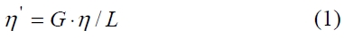
where,
The antenna efficiency,
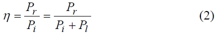
where,
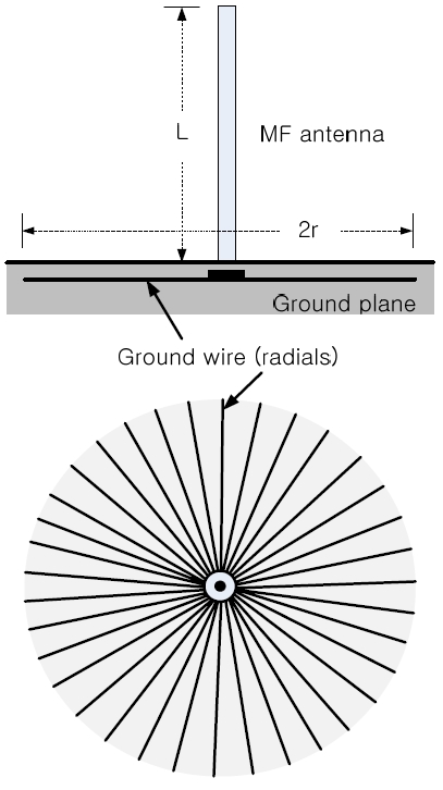
From (1), the radiation efficiency is dependent on the antenna gain and the antenna efficiency. To improve the antenna gain, the antenna is designed with a proper antenna length. Also, the antenna efficiency is dependent on the conductivity and physical size of the ground plane. To enhance the radiation efficiency, therefore, the MF antenna should be installed on the ground plane with large enough physical dimensions and a good conductivity. The ground connection of the antenna is a series of radials that all group into a connection at the base of the antenna. The radial ground for MF antenna is shown in Fig. 1.
Assuming that the ground plane is a perfect conductor in Fig. 1, the MF antenna efficiency of (2) can be defined as:
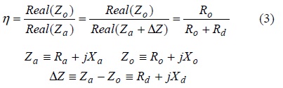
where,
It is known from (3) that it is important to achieve a low grounding impedance, which is needed to have an adequate ground plane. In general, the radius (r) of the radial ground is designed over the length (L) of the MF antenna. The radials (ground wires) are installed 30 to 50 cm below the earth’s surface. The number of the ground wires is used according to the output power capability of the DGPS, which is basically used with 60 to 240 wires.
In case the physical dimensions of the radial ground are small (in general
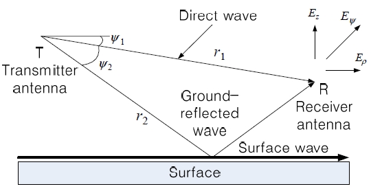
From Fig. 2, the voltage V induced at the receiving antenna R from the transmitting antenna T with a distance of
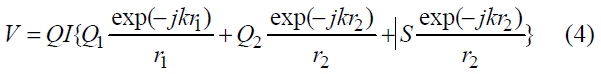
where
In (4), the MF wave is propagated as surface wave using vertical polarization. The electric field intensity for the MF surface wave can be expressed as:
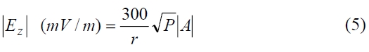
where
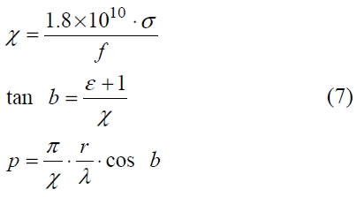
The attenuation factor in the MF band is produced from the frequency (
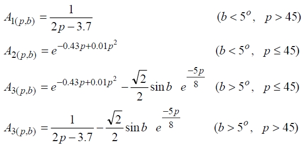
where the parameters in (6) are as follows:
It is shown in form (6) that the attenuation factor is the function of the parameters of
III. MF FIELD INTENSITY AND RADIATION EFFICIENCY OF KOREAN DGPS
To deduce the radiation efficiencies of the Korean DGPS, the electric field intensities for the Korean DGPS are measured at the proper points. Also, the electric field intensities for the measured points are theoretically produced from (5) and (6).
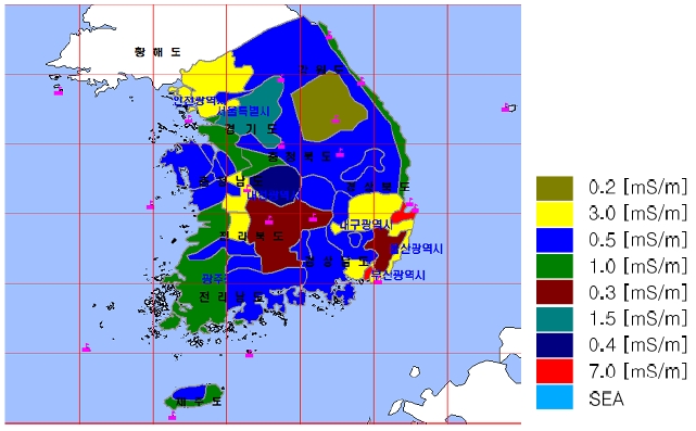
Then, the radiation efficiencies for the Korean DGPS of(1) are deduced by comparing the measured data and theoretical data. The conductivity data of the Korean territory is used in (7), which is shown in Fig. 3. From Fig. 3, Millington’s method is adopted for the mixed paths, which means the propagation path including grounds with different conductivities [7].
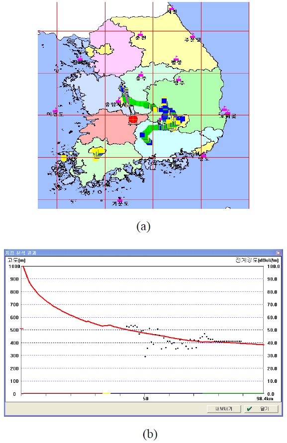
Fig. 4 shows the measured data and theoretical data marked on the Korean map in the case of the Muju DGPS. The theoretical electric field intensities are produced for the same points (latitude and longitude) with measured points. To deduce the radiation efficiency of the DGPS, the data produced theoretically are compared on the map on which the measured data are marked.
The data fitting is accomplished over the propagation distance of 80 km, which is the service area of a land-based DGPS. Fig. 4b shows the theoretical data fitted to the measured data under the condition of a radiation efficiency of 40%. It is shown from Fig. 4b that the Muju DGPS with the radiation efficiency of 40% would radiate an MF wave that almost agrees with the measured electric field intensities.
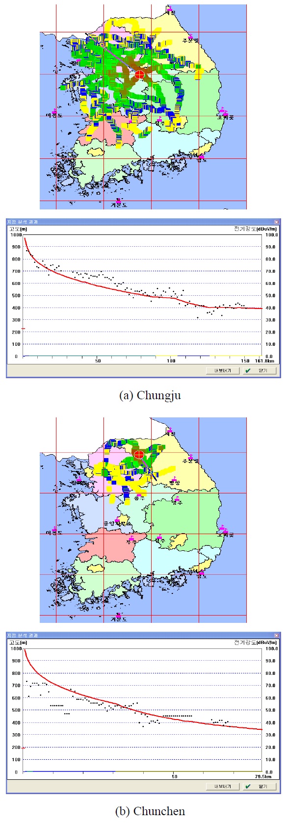
From the data fitting of the measured data and theoretical data, the radiation efficiencies of the Korean DGPS can be deduced. Fig. 5 shows the data fitting for the land-based DGPS of Chungju and Chunchen. The radiation efficiencies of Chungju and Chunchen DGPS are 28.6% and 8.86%,respectively. The antennas of the land-based DGPS are the top-loaded antenna type with the length of 90 m, while the antenna of the Chunchen DGPS is new technology antenna (NTA) with a 24.9 m length. Therefore, it is clear that the radiation efficiency of the Chunchen DGPS is lower than that of the other land-based DGPS. This is because the antenna of the Chunchen DGPS is shorter in length.
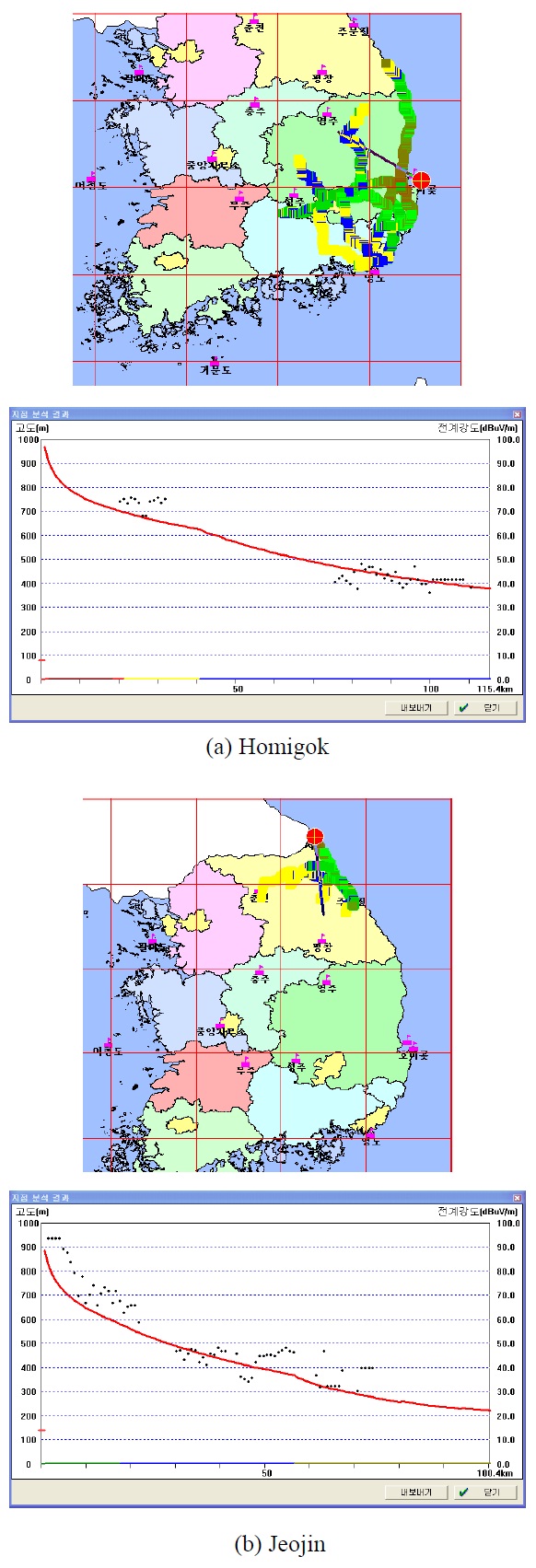
Fig. 6 shows the data fitting for the ocean-based DGPSs,which are installed at the seaside or on islands. It can be seen from Fig. 6 that the radiation efficiencies for ocean-based DGPSs are lower than those of land-based DGPS. In the ocean-based DGPSs, the shorter antennas are installed on the ground without large enough dimensions.
The radiation efficiencies of the ocean-based DGPS are in the range of 0.75 to 16%.
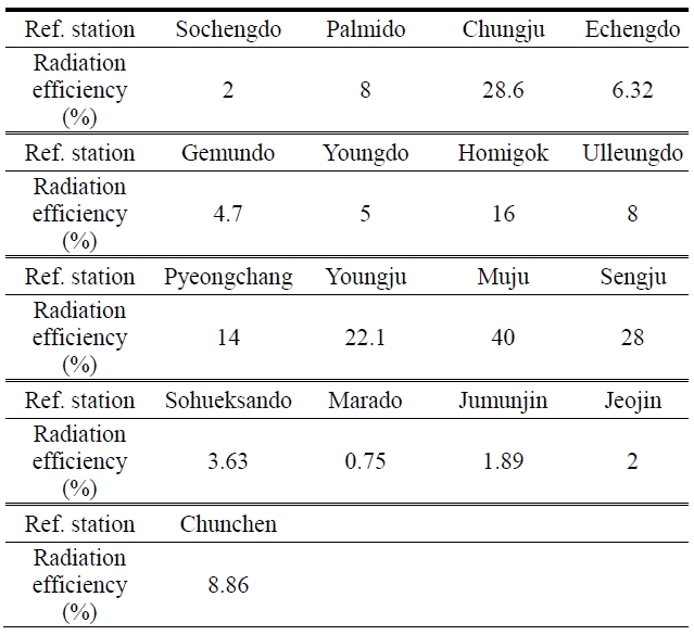
By data fitting for all of the land-based DGPSs and ocean-based DGPSs, the radiation efficiencies for the Korean DGPS are deduced. Table 1 shows the radiation efficiencies for DGPS throughout the Korea.
[Table 1.] Radiation efficiencies for Korean differential global positioning system

Radiation efficiencies for Korean differential global positioning system
In Table 1, it can be seen that the Marado DGPS among the ocean-based DGPSs shows a very low radiation efficiency. The antenna of the Marado DGPS with a 24.9 m length was installed on the ground with a rock bed. Besides its shorter antenna length, the effect of a poor ground plane severely degrades the radiation efficiency of the Marado DGPS. Most of the ocean-based DGPS were installed on ground planes with low conductivities. It is clear that the DGPS MF antenna should be installed on the ground plane with large enough physical dimensions and good conductivity.
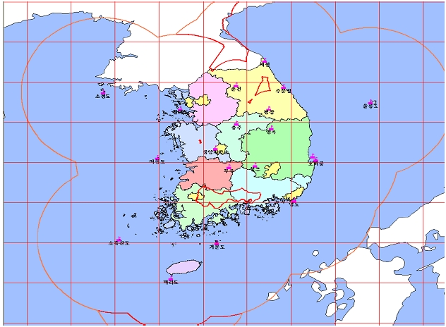
By applying the deduced radiation efficiencies, the service area of the Korean DGPS is predicted. Fig. 7 shows the service area of the Korean DGPS applying the deduced radiation efficiencies. In Fig. 7, there are some shadow areas in some parts of Kangwondo and Jeonnam. The factors affecting the shadow areas can be considered to be the propagation loss due to mountainous regions and radiation powers due to low radiation efficiencies. To enhance the service area, it is important to design the MF antenna system with a high radiation efficiency.
In this paper, the radiation efficiencies for Korean DGPS are deduced from the DGPS radiation power. The radiation efficiencies of the DGPS were analyzed based on the measured radiation power and theoretical electric field intensity.
The radiation efficiencies of the Korean ocean-based DGPSs were lower than those of the land-based DGPSs. In general, the ocean-based DGPSs were installed on narrow ground planes with low conductivities. It was concluded that to improve the radiation efficiency, an MF antenna should be designed with a proper antenna length and installed on a ground plane with good conductivity and large enough physical dimensions. Also, the Korean DGPS service area was predicted from the deduced DGPS radiation efficiencies. To enhance the service area, it is important to design the MF antenna system with a high radiation efficiency.