Since the discovery of multi-walled carbon nanotubes (MWCNTs) [1], CNTs have been synthesized with various methods such as arc discharge [2, 3], laser vaporization [4], and chemical vapor deposition (CVD) [5-17]. Among various synthesis methods, the CVD technique has an advantage because it can control the diameter, the length, and the structure of CNTs through various process parameters. It is well known that aligned CNTs are important for a number of applications, such as field emission display and sensors. Aligned CNTs were grown on iron oxide particles embedded in mesoporous silica at 600℃ [5]. Subsequently, aligned CNTs were grown by plasma CVD [11-14] or thermal CVD
Recently, the addition of sulfur was found to be effective in promoting the growth and yield of single-walled carbon nanotubes (SWCNTs) and double-walled carbon nanotubes(DWCNTs) [20-23]. More recently, vertically aligned SWCNT film was grown by thermal CVD using ethanol decomposition over a mono-dispersed Co-Mo catalyst on quartz substrates [24, 25], and water-stimulated enhanced catalytic activity resulted in massive growth of superdense and vertically aligned SWCNT forests with heights up to 2.5 mm [26]. However, there were no reports on the synthesis of well-aligned thin MWCNTs on the substrate. We consider that thin MWCNTs can promise good field emission properties similar to SWCNTs but indicate better emission stability compared with SWCNTs.
In this paper, we report that well-aligned MWCNTs with a thin diameter of about 10 nm were successfully synthesized by catalytic CVD (CCVD) onto Al/Fe thin films on Si wafers. We investigated that an addition of hydrogen sulfide (H2S) was found to be effective in increasing the growth rate of CNTs and inducing the vertical direction of CNT growth. Interestingly, the well-aligned thin MWCNTs indicated very a large inside hollow core compared with previous MWCNTs. The well-aligned thin MWCNTs showed good field emission properties and strong emission stability. We also suggest a possible growth mechanism for thin MWCNTs with a large inside hollow core.
Well-aligned MWCNTs were successfully synthesized by CCVD on silicon substrate. The MWCNT growth was carried out on a quartz tube furnace with 20 mm diameter and 300 mm heating zone. Initially, Al (10 nm) and then Fe (1 nm) thin films were deposited onto the n-type Si (100) substrates using thermal evaporation. Pure Ar (99.9%), H2 (99.9%), C2H2 (99.99%), and H2S (1%, diluted by Ar) were used in this experiment. The substrates were placed in the center of the heating zone and the furnace was heated to a temperature of 800oC under 1000 sccm Ar and 50 sccm H2 at one atmosphere. The CNTs were synthesized at 800℃ with C2H2 (30 sccm) and diluted H2S (0~80 sccm) flow under Ar/H2 (1000/50 sccm) flow for 20 min. Scanning electron microscopy (SEM, S-4700, Hitachi, Japan), high-resolution transmission electron microscopy (HRTEM, H-9000, Hitachi, Ja-pan), and micro-Raman spectroscopy were used to characterize the CNTs. For Raman measurement, the 514.5 nm line of an Ar+ laser was used as the excitation source. The emission current was monitored with a Keithley 6517A electrometer and recorded at 1.0 s intervals by applying a sweep step of 20 V.
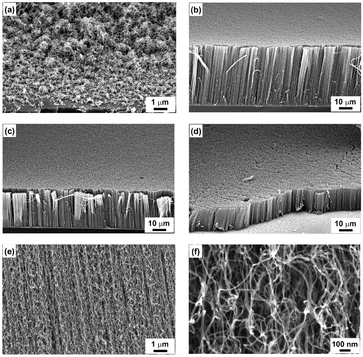
Figs.1a-d show the SEM images of the morphologies of as-grown CNTs on the Fe/Al thin film deposited on Si substrates according to diluted H2S flow rate. By supplying less than 15 sccm of diluted H2S to the reactor, the CNTs are laid down on the substrate as shown in Fig.1a. However, the synthesized CNTs are well aligned on the substrate when over 30 sccm of the diluted H2S is introduced to the reactor. From SEM observation, after 20 min of reaction time, the lengths of carbon nanotubes
at 30, 50, and 80 sccm H2S flow rate are 45, 27, and 17 μm, respectively, as shown in Figs.1b-d. Under a higher H2S flow rate of over 100 sccm, there was no appearance of carbon products on the substrate. Figs.1e and f show the high-magnified SEM images of the well-aligned multiwalled CNTs, which indicate curly shaped high-purity CNTs. They show a uniform diameter of about 10 nm over the carbon filaments.
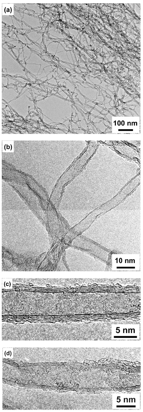
Figs. 2a and b show the TEM images of the as-grown well-aligned MWCNTs after dispersion on a Cu grid. The synthesized carbon products reveal thin MWCNTs with diameters less than 10 nm. From HRTEM observation, besides thin MWCNTs with five grapheme layers (Fig.2 c), we can see triple-walled CNTs (Fig.2 d) with a very large inside hollow core. It is interesting to find thin MWCNTs with such a large inside hollow core from this work. We consider that this result may be related to the introduction of an H2S additive. Here, we used Al/Fe thin film deposited on Si wafers as a catalyst for CNT growth. When the substrate is heated to 800℃ in a CVD furnace, the Al layer melts and forms small droplets, which absorb the residual oxygen inside the furnace and oxidize quickly to form thermally stable Al2O3 clusters. The formed Al2O3 clusters provide the support for the formation of Fe nanoparticles, which catalyze the growth of the thin MWCNTs.
Sulfur has been found to play a key role in producing carbon filaments by the floating catalyst method and in enhancing the productivity of carbon fibers [27, 28]. Low coverage of sulfur in the metal surface layers may favor carbon-carbon bond rupture and precipitation of the carbon filament [28]. Our experiments showed that optimal amounts of H2S additive are necessary to increase the growth rate of MWCNTs and to produce the well-aligned CNTs. In our experiments, the roles of H2S additive may be expressed by the following reactions:


In this reaction, we consider that the growth rate of CNTs largely increase because H2S can effectively remove amorphous carbon coating from catalysts (reaction 1). On the other hand, H2S additives can partly empoison the catalysts (reaction 2) and change catalyst surface morphology, which can reduce the number of catalytically active sites and would limit the growth direction of the carbon nanotubes. Therefore, well-aligned CNTs are easily synthesized when optimal amounts of H2S additive are used. However, H2S also might damage CNTs (reaction 3). To synthesize high quality aligned CNTs, the H2S partial pressure and the deposition time must be controlled. In general, sulfur can accelerate agglomeration of catalyst particles on the sub-strate, resulting in large sized catalyst particles. We believe that the thin MWCNTs with a large inside hollow core appear in this method. To understand details of the mechanism, further study is necessary. We believe that these thin MWCNT arrays with large inside hollow cores will be more promising in the hydrogen-storage application [29] or element filling application [30].
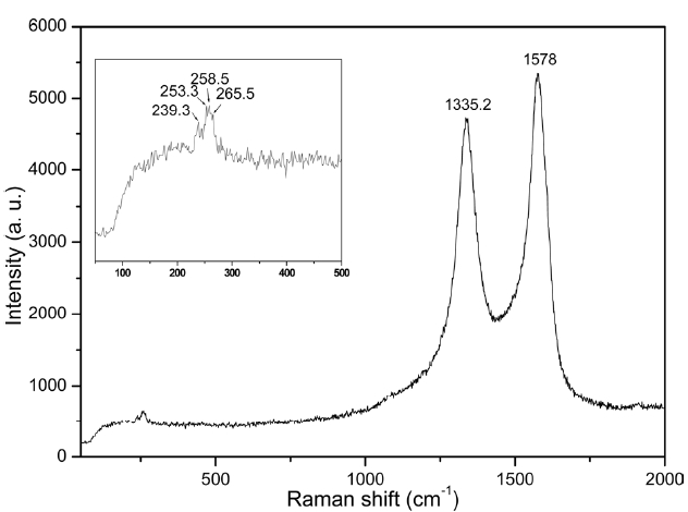
Fig. 3 shows a typical Raman spectrum of the as-grown aligned CNTs excited by a 514.5 nm laser. The G-band and the D-band that indicate the tangential stretching mode are located at 1578 and 1335.2 cm-1, respectively. Radial breathing modes (RBM) are also identified at the low frequency of the Raman spectrum. Four main RBM peaks (239.3, 253.3, 258.5, and 265.5 cm-1) identify that the produced carbon products contain a few SWCNTs or DWCNTs besides thin MWCNTs. We could find a few SWCNTs or DWCNTs from HRTEM observation besides thin MWCNTs sometimes.
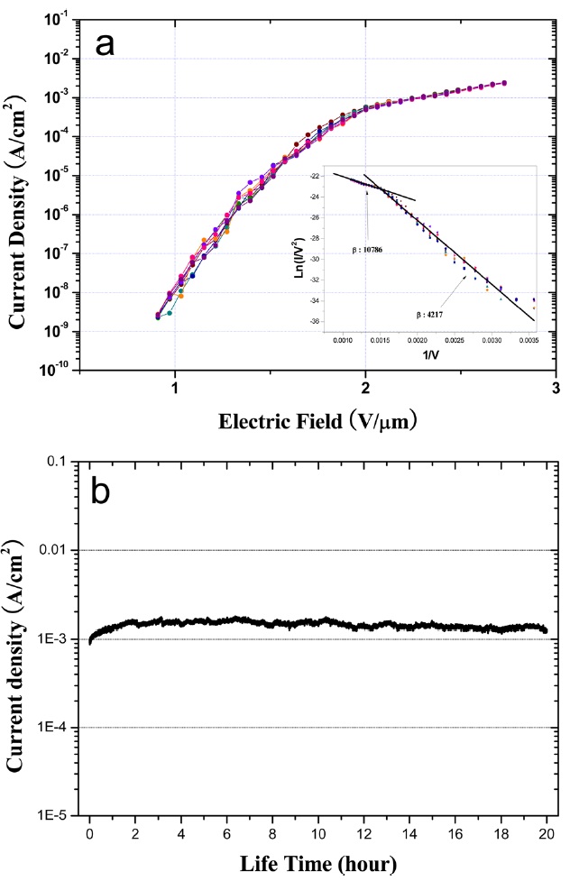
Fig. 4 shows the field emission properties for as-grown well-aligned thin MWCNTs as shown in Fig.1d. Before the emission current measurement, we conducted electrical annealing to obtain stable field emission properties. After the electrical annealing process at the current density of about~1 mA/cm2 for 1 h, we confirmed that the emission current was more stabilized. Fig.4 a illustrates the emission current density and corresponding Fowler-Nordheim (FN) plot. From Fig.4 a, the turn-on electric field (corresponding to the current density of 0.1 μA/cm2) is about 1.1 V/μm and the emission current density is about 2.0 mA/cm2 at an applied field of 2.7 V/μm, which indicates good field emission performance. We consider that the thin MWCNT array is useful to a field emitter in a flat panel display. The FN plot usually presented in the literature is also shown in the inset of Fig.4 a. The field enhancement factorβ can be calculated from the slope of the FN plot if the work function of the emitter is known. From the inset of Fig. 4a, the calculated β values at higher and lower electric field regions are about 10 786 and 4217, respectively. Fig.4b shows emission current stability from the as-grown MWCNT arrays during a long lifetime measurement. MWCNTs reveal stable emission current density over 20 h even though a little fluctuation of emission current appears due to the morphology of CNT tips. The thin MWCNTs promise good emission properties similar to SWCNTs while they indicate much better emission stability compared with SWCNTs.
In summary, we successfully synthesized well-aligned thin MWCNTs using a CCVD method with H2S additives. The as-grown carbon products indicated thin MWCNTs with diameters less than 10 nm, and they showed 5-7 graphene layers and a large inside hollow core compared with previous MWCNTs. The produced carbon products sometimes contain triple-walled CNTs and tetra-walled CNTs besides thin MWCNTs. The H2S additives increased the growth rate of MWCNTs and induced the vertical growth direction of MWCNTs. Moreover, H2S played a key role to form thin MWCNTs with a large inside hollow core. The turn-on voltage for the thin MWCNTs arrays was found to be about 1.1 V/μm at current density of 0.1 μA/cm2, and the emission current density arrays reached 2.0 mA/cm2 at a bias field of 2.7 V/μm.