Satellite laser ranging (SLR), a precise ranging system using laser, is known as the system that measures satellite orbit the most precisely among all the currently available ranging systems. Ranging with SLR is performed by firing laser toward the geodetic satellite to observe from the ground observatory, detecting the returning laser beam reflected by the laser retro-reflector array (LRA) installed on the satellite with an optical detector, and thus measuring the round-trip time. In other words, by precisely measuring the momentary duration of time between laser-transmission and laser-reception, the time-of-flight is obtained and thus the momentary distance between the ground observatory and the satellite is determined(Park et al. 2005). Korea Astronomy and Space Science Institute (KASI) is developing accurate ranging system for geodetic observation-mobile (ARGO-M), a mobile SLR system. ARGO-M consists of five main subsystems including optical subsystem (OPS), opto-electronics subsystem(OES), laser subsystem (LAS), tracking and mount subsystem (TMS) and ARGO operation system (AOS) in additions to a dome and a mobile container (Lim et al.2010) . Among these, AOS is the system that controls the entire subsystems needed for the laser observation, make a comprehensive judgment regarding the environment and eventually reflects the judgment to the observation(Seo et al. 2009). Moreover, it plays the role of integrating and processing the data obtained from actual observation.AOS can be considered as the core subsystem since it controls the overall observation operation and produces the result data based on a number of interfaces combining the components necessary to operate the SLR normally. This AOS can be divided into developed items in detail and the main categories are the operation and control system and the operation equipment. The software configuration items that belong to the operation and control system part are interface control system (ICS), observation control system (OCS), data analysis system (DAS) and remote operation system (ROS). The operation equipment part is composed of the radar for aircrafts detection, weather monitoring system, timing system, network system, network security solution, and surveillance camera.
The preliminary design is the development stage where the design is actually carried out based on the analysis of not only the previously identified requirements but also the specification. Since the output produced at this stage provides the basis for the final design that is to be conducted in the following stage of detailed design, the preliminary design is a critical development stage. Thus, this article describes the main research works performed at the preliminary design stage by the AOS, dividing them into three different units. Firstly, the study of the system design within the AOS is presented. Secondly, the design of the operation and control system part which is mainly by the software development is explained. Finally, the design of the equipment operation part which is mainly by the development of interface needed at the time of research equipment introduction is presented. Initially, the operation scenario at the subsystem level was derived for the system design of the operation system unit. Individual operation scenarios were prepared for each of the differentiated operation modes. In addition, the realization of the software functions could be directly applied by suggesting the relationship between the individual configuration items and the modes from the operation mode differentiation. We carried out the derivation of such operation scenario through the operation software logic analysis in Graz SLR Observatory (in Institut fur Weltraumforschung), Austria, during the time of the preliminary design. For the information, Graz SLR Observatory has the highest precision in SLR observation. Hence, KASI has concluded an agreement for ARGO-M development and conducted technological cooperation with the observatory. In this way, the analysis was carried out not only for the identification of the interfaces with other subsystems but also for the derivation of the operation scenarios and the configuration budget analysis results are presented together.
The preliminary design of the operation and control part was carried out based on the development methodology of the software engineering sector. Following this methodology gives various unified modeling language (UML) diagrams. In addition, design through the Iterative and Incremental Process methodology (IBM 2009) can continuously provide feedback to the users and the design can be corrected. This article focused on how to realize the user’s requirements on the computer. The functional requirements of the key systems of the operation and control system part including ICS, OCS and DAS were divided into the core, common and integrated functions to describe the identification of the configuration items. Moreover, the individual components of the hardware and software related to the operational environment were analyzed and the design was discussed. The constitution of the main screen prototype that is the user interface is also presented. The preliminary design of the operation equipment part was mainly performed by the analysis of the interface between the candidate products of the corresponding equipment and the computers that will operate the products. In this article, we describe the interface analysis of the timing system and the radar equipment for the vehicle detection that require the foremost establishment.
The followings are the preliminary design study that is discussed respectively for the AOS system level, the operation and control system part and the operation equipment part.
2.1 Operation Status and Scenario
The operation status of AOS was distinguished into three statuses in terms of the functions that should be realized in the preliminary design process: pre-observation status, ground calibration status or actual observation status, and post-analysis status. In the pre-observation status, the operator who has undergone the previously permitted authentication procedure approaches ICS and OCS, and checks the operating state of the entire subsystem. Then, the calibration mode or observation mode is chosen through the mode control. In addition, the initial procedure is performed to verify the setting values including the previously prepared orbit data of the tracking target satellite. In the ground calibration status or the actual observation status, the ground target is managed under the setting that has been already completed or the real-time scheduling is performed for the satellite to observe. Additionally, initialization of the system that needs maneuvering or that is controlled by the AOS is carried out. After finishing the initialization, the mission is carried out or the observation is conducted with the input from the manual control of the operation, if necessary.
Following the time of predetermined ground calibration or the time when satellite observation is possible, the observation result and the mode values are saved and then the system is shut down or the next task is performed in the same manner. In the post-analysis status, after a path of the satellite to observe is finished, the observation data save in OCS is transferred to DAS which independently performs analytical task including removal of noise. Following this, the normal point, the final output of the SLR observation, is generated and it is reported to international laser ranging service (ILRS) to complete the after-analysis procedure. The normal point is used as the international standard observation data of high-precision data processing software such as GEODYN. The SLR observation data is used for the determination of international standard coordinate system and study of the earth’s gravity field, the earth’s rotation and the crustal movement monitoring. Fig. 1 illustrates the modes applicable to each system and selection framework. Fig. 2 schematically demonstrates the individual operation status in the form of activity diagram, one of the UML diagrams.
2.2 Analysis of the Interface and Configuration Budget
The interfaces of AOS are divided into external interface and internal interface. The external interface indicates the interface between AOS and other subsystems such as the opto-electronic section, the tracking mount section, the optical system, the laser section and the dome. The internal interface indicates the interface among the configuration items that are the sub-components under the AOS. In the preliminary design stage, the study was focused on the analysis of the external interfaces. For the data structure design, the data ele-
ment identifiers were summarized and the analysis was carried out for each identifier about the communication method, data format, unit, the minimum and maximum of the data range, data resolution, transmission period, etc. Fig. 3 illustrates such interface analysis focusing on the flow of data. The specific contents of the individual items of the interfaces will be completed in the detailed design stage which is the next development stage, after consultation with the corresponding subsystems. ARGO-M will be operated as an observatory in the form of a container so that it can be moved to the desired observation location through a specially designed vehicle and
[Table 1.] AOS configuration budget analysis
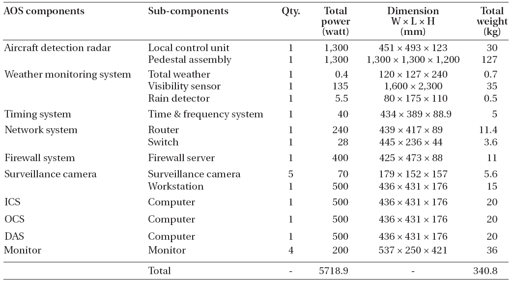
AOS configuration budget analysis
installed there. Budget analysis was performed for all the component units that constitute the operation system with respect to the design specifications needed for the container fabrication including the power consumption, configuration size and the weight (Table 1).
3. PRELIMINARY DESIGN OF THE OPERATION AND CONTROL SYSTEM PART
Although requirement analysis usually focuses on the concepts of the application areas, the focus is switched to the concept of computer at the stage of software design. The requirements identified at the stage of analysis are the user’s requirements about what to design, while design is the procedure of how to realize such objectives on computer (Youn 2009). The preliminary design in the operation and control system part includes the requirements analysis, configuration items identification and object modeling for ICS, OCS and DAS, the key systems of this part. In the procedure of the requirements analysis, the requirements of the individual systems were collected, classified into functional requirements and nonfunctional requirements, case by case, and only the functional requirements were reorganized. Then, the range of the system realization was defined by deriving not only the usecase diagrams but also the requirement specifications.
The software configuration items are generated during the software development. Not only the thousands of specification that are produced during a large software project development but also one of the paragraphs in the specification or one of the case among many test cases can be considered as configuration item (Song et al. 2004). Hence, for the functional requirements, the configuration items were distinguished into core, common and integrated functions using package diagram. Fig. 4 shows the configuration items of OCS for each of the service which was illustrated in the form of general diagram instead of package diagram for easy understanding. In addition to deriving the configuration items, the individual components of the hardware and software related to the operation environment were analyzed and designed (Fig. 5), and the main screen prototype which is the user
interface was established (Fig. 6). The external and internal interfaces of the individual systems were defined for the preliminary design. For these design tasks, the analysis and design were carried out using UML and, in the process, usecase, sequence, state and package diagram were prepared when needed. The various diagrams and models derived will be presented as a separate research result after completing the entire flow through detailed design.
4. PRELIMINARY DESIGN OF THE OPERATION EQUIPMENT PART
Complete products will be introduced for most of the operation equipments, and only the interface of the computer in the operating system that will communicate with the equipments will be developed for the establishment of the part. The establishment time depends on the time needed for the development, the time when the equipment is required and the installation environment and conditions of different equipments. Among the ARGO-M subsystems, the AOS, the opto-electronic section and the tracking mount require precise timing or relevant frequency for the functioning at the determined time and the data synchronization between systems. The timing system provides the precise standard timing and relevant frequency. In addition, since the equipment is necessary for the development of subsystems, it was established earlier than all others and now it is under operation. Fig. 7 shows the timing information, types of frequency provided by the timing system and the quantity of port. The timing and frequency distribution of the timing system includes of an Ethernet port to provide network time protocol (NTP) for the synchronization between the timing server and the computer through the network. It also includes four ports to provide the 10 MHz timing frequency in the form of analog sine wave with Enhanced Low Phase Noise (Symmetricom Inc. 2008). Moreover, it was designed to include five ports to provide standardized timing code and pulse in 1 pulse per second period as well as five ports to convey the universal time coordinated in the form of inter range instrumentation group-B (IRIG-B).
This laser hazard reduction system (LHRS) provides a means of detecting aircraft and shutting off the laser before the aircraft intersects the transmitted laser beam. The radar can detect aircraft out to a range greater than the nominal ocular hazard distance (McGarry et al. 2008). For the detecting function, the mount with the driving mechanism that is aligned to the same direction of the laser radiation is installed to the radar. Honeywell, USA, is the only company in the world that develops and provides the radar exclusively for SLR. The LHRS consists of the following functional elements: radar transmitter, radar receiver, parabolic antenna, pedestal assembly, radome assembly, and control electronics (Honeywell Technology Solutions Inc. 2010). The local control unit (LCU) which is the control part of the radar is installed inside the operation room so that the operator can monitor and the remote control unit (RCU) is installed beneath the radome. The maximum distance between LCU and RCU should be less than 100 m. To align the laser firing direction with the radar detection direction during SLR observation, LCU should receive the real-time location information from the OCS computer of the AOS. The relay contacting point signal is directly transmitted to the laser controller in order to directly stop the laser firing immediately after a flying vehicle is detected. Fig. 8 shows the constitution design for the interface analysis of the radar controlling part, the OCS computer and the laser controller. Following the timing system, the establishment of the detection radar is being performed considering the time required for the development and other factors. Besides, other operational equipment such as the weather monitoring system, network system, network security solution, and surveillance camera will be established according to the time to complete the mobile container.
In this article, the results of the preliminary design in relation to the operation system development were described dividing them into the operation system units, the operation and control system part and the operation equipment part. First, in the operation system unit, the operation statuses were distinguished as the pre-observation status, ground calibration or actual observation status and the post-analysis status. The operation scenarios for each of the statuses were illustrated in the form of activity diagram. In addition, the mode control was presented for the corresponding systems for the mode switching. The relationship of the external and internal interfaces of the operating system was analyzed and the data flow between them was derived. Additionally, we presented the configuration budget analysis results to install the mobile container for the system integration. In the preliminary design of the operation and control system part, the configuration items were identified and the hardware and software composition was designed. Besides, the prototype model of the main screen which is the user interface was established. In the operation equipment part, the user environment and the interface analysis was carried out for the timing system that should be preferentially established and the vehicle detection radar that requires certain duration of fabrication. In the detailed design process which is the next development stage, we will present the object modeling results derived through the Iterative and Incremental Process methodology in the case of software development. Also, the system interface and the user interface that have been analyzed and designed until now will be realized and verified through the development of the design verification model. For the operation equipment, detailed design of the meteorological equipments, network system, security solution and the security camera will be performed according to the time to complete the mobile container.